rounding.scad
Routines to create rounded corners, with either circular rounding, or continuous curvature rounding with no sudden curvature transitions. Provides rounding of corners or rounding that preserves corner points and curves the edges. Also provides some 3D rounding functions, and a powerful function for joining two prisms together with a rounded fillet at the joint.
To use, add the following lines to the beginning of your file:
include <BOSL2/std.scad>
include <BOSL2/rounding.scad>
-
-
round_corners()– Round or chamfer the corners of a path (clipping them off). [Path] -
smooth_path()– Create smoothed path that passes through all the points of a given path. [Path] -
path_join()– Join paths end to end with optional rounding. [Path] -
offset_stroke()– Draws a line along a path with options to specify angles and roundings at the ends. [Path] [Region]
-
-
Section: Three-Dimensional Rounding
-
offset_sweep()– Make a solid from a polygon with offset that changes along its length. [Geom] [VNF] -
convex_offset_extrude()– Make a solid from geometry where offset changes along the object's length. [Geom] -
rounded_prism()– Make a rounded 3d object by connecting two polygons with the same vertex count. [Geom] [VNF] -
bent_cutout_mask()– Create a mask for making a round-edged cutout in a cylindrical shell. [Geom] -
join_prism()– Join an arbitrary prism to a plane, sphere, cylinder or another arbitrary prism with a fillet. [Geom] [VNF]
-
The functions and modules in this file support two different types of roundovers and some different mechanisms for specifying
the size of the roundover. The usual circular roundover can produce a tactile "bump" where the curvature changes from flat to
circular. See https://hackernoon.com/apples-icons-have-that-shape-for-a-very-good-reason-720d4e7c8a14 for details.
We compute continuous curvature rounding using 4th order Bezier curves. This type of rounding, which we call "smooth" rounding,
does not have a "radius" so we need different ways to specify the size of the roundover. We introduce the cut and joint
parameters for this purpose. They can specify dimensions of circular roundovers, continuous curvature "smooth" roundovers, and even chamfers.
The cut parameter specifies the distance from the unrounded corner to the rounded tip, so how
much of the corner to "cut" off. This can be easier to understand than setting a circular radius, which can be
unexpectedly extreme when the corner is very sharp. It also allows a systematic specification of
corner treatments that are the same size for all corner treatments.
The joint parameter specifies the distance
away from the corner along the path where the roundover or chamfer should start. This parameter is good for ensuring that
your roundover will fit on the polygon or polyhedron, since you can easily tell whether you have enough space, and whether
adjacent corner treatments will interfere.
For circular rounding you can use the radius or r parameter to set the rounding radius.
For chamfers you can use width to set the width of the chamfer.
The "smooth" rounding method also has a parameter that specifies how smooth the curvature match is. This parameter, k,
ranges from 0 to 1, with a default of 0.5. Larger values gives a more
abrupt transition and smaller ones a more gradual transition. If you set the value much higher
than 0.8 the curvature changes abruptly enough that though it is theoretically continuous, it may
not be continuous in practice. If you set it very small then the transition is so gradual that
the length of the roundover may be extremely long, and the actual rounded part of the curve may be very small.
Figure 1: Parameters of a "circle" roundover

Figure 2: Parameters of a "smooth" roundover with the default of k=0.5. Note the long, slow transition from flat to round.

Figure 3: Parameters of a "smooth" roundover, with k=0.75. The transition into the roundover is shorter, and faster. The cut length is bigger for the same joint length.

Figure 4: Parameters of a "smooth" roundover, with k=0.15. The transition is so gradual that it appears that the roundover is much smaller than specified. The cut length is much smaller for the same joint length.

Figure 5: Parameters of a symmetric "chamfer".

Synopsis: Round or chamfer the corners of a path (clipping them off). [Path]
See Also: smooth_path(), path_join(), offset_stroke()
Usage:
- rounded_path = round_corners(path, [method], [radius=], [cut=], [joint=], [closed=], [verbose=]);
Description:
Takes a 2D or 3D path as input and rounds each corner
by a specified amount. The rounding at each point can be different and some points can have zero
rounding. The round_corners() function supports three types of corner treatment: chamfers, circular rounding,
and continuous curvature rounding using 4th order bezier curves. See
Types of Roundover for details on rounding types.
You select the type of rounding using the method parameter, which should be "smooth" to
get continuous curvature rounding, "circle" to get circular rounding, or "chamfer" to get chamfers. The default is circle
rounding. Each method accepts multiple options to specify the amount of rounding. See
Types of Roundover for example diagrams.
- The
cutparameter specifies the distance from the unrounded corner to the rounded tip, so how much of the corner to "cut" off. - The
jointparameter specifies the distance away from the corner along the path where the roundover or chamfer should start. This makes it easy to ensure your roundover will fit, so use it if you want the largest possible roundover. - For circular rounding you can use the
radiusorrparameter to set the rounding radius. - For chamfers you can use the
widthparameter, which sets the width of the chamfer edge.
As explained in Types of Roundover, the continuous curvature "smooth"
type of rounding also accepts the k parameter, between 0 and 1, which specifies how fast the curvature changes at
the joint. The default is k=0.5.
If you select curves that are too large to fit the function will fail with an error. You can set verbose=true to
get a message showing a list of scale factors you can apply to your rounding parameters so that the
roundovers will fit on the curve. If the scale factors are larger than one
then they indicate how much you can increase the curve sizes before collisions will occur.
The parameters radius, cut, joint and k can be numbers, which round every corner using the same parameters, or you
can specify a list to round each corner with different parameters. If the curve is not closed then the first and last points
of the curve are not rounded. In this case you can specify a full list of points anyway, and the endpoint values are ignored,
or you can specify a list that has length len(path)-2, omitting the two dummy values.
If your input path includes collinear points you must use a cut or radius value of zero for those "corners". You can choose a nonzero joint parameter when the collinear points form a 180 degree angle. This will cause extra points to be inserted. If the collinear points form a spike (0 degree angle) then round_corners will fail.
Examples:
-
method="circle", radius=2: Rounds every point with circular, radius 2 roundover -
method="smooth", cut=2: Rounds every point with continuous curvature rounding with a cut of 2, and a default 0.5 smoothing parameter -
method="smooth", cut=2, k=0.3: Rounds every point with continuous curvature rounding with a cut of 2, and a very gentle 0.3 smoothness setting
The number of segments used for roundovers is determined by $fa, $fs and $fn as usual for
circular roundovers. For continuous curvature roundovers $fs and $fn are used and $fa is
ignored. Note that $fn is interpreted as the number of points on the roundover curve, which is
not equivalent to its meaning for rounding circles because roundovers are usually small fractions
of a circular arc. As usual, $fn overrides $fs. When doing continuous curvature rounding be sure to use lots of segments or the effect
will be hidden by the discretization. Note that if you use $fn with "smooth" then $fn points are added at each corner.
This guarantees a specific output length. It also means that if
you set joint nonzero on a flat "corner", with collinear points, you will get $fn points at that "corner."
If you have two roundovers that fully consume a segment then they share a point where they meet in the segment, which means the output
point count will be decreased by one.
Arguments:
| By Position | What it does |
|---|---|
path |
list of 2d or 3d points defining the path to be rounded. |
method |
rounding method to use. Set to "chamfer" for chamfers, "circle" for circular rounding and "smooth" for continuous curvature 4th order bezier rounding. Default: "circle" |
| By Name | What it does |
|---|---|
radius / r
|
rounding radius, only compatible with method="circle". Can be a number or vector. |
cut |
rounding cut distance, compatible with all methods. Can be a number or vector. |
joint |
rounding joint distance, compatible with method="chamfer" and method="smooth". Can be a number or vector. |
width |
width of the flat edge created by chamfering, compatible with method="chamfer". Can be a number or vector. |
k |
continuous curvature smoothness parameter for method="smooth". Can be a number or vector. Default: 0.5 |
closed |
if true treat the path as a closed polygon, otherwise treat it as open. Default: true. |
verbose |
if true display rounding scale factors that show how close roundovers are to overlapping. Default: false |
Example 1: Standard circular roundover with radius the same at every point. Compare results at the different corners.
include <BOSL2/std.scad>
include <BOSL2/rounding.scad>
$fn=36;
shape = [[0,0], [10,0], [15,12], [6,6], [6, 12], [-3,7]];
polygon(round_corners(shape, radius=1));
color("red") down(.1) polygon(shape);
Example 2: Circular roundover using the "cut" specification, the same at every corner.

include <BOSL2/std.scad>
include <BOSL2/rounding.scad>
$fn=36;
shape = [[0,0], [10,0], [15,12], [6,6], [6, 12], [-3,7]];
polygon(round_corners(shape, cut=1));
color("red") down(.1) polygon(shape);
Example 3: Continous curvature roundover using "cut", still the same at every corner. The default smoothness parameter of 0.5 was too gradual for these roundovers to fit, but 0.7 works.
include <BOSL2/std.scad>
include <BOSL2/rounding.scad>
$fn=36;
shape = [[0,0], [10,0], [15,12], [6,6], [6, 12], [-3,7]];
polygon(round_corners(shape, method="smooth", cut=1, k=0.7));
color("red") down(.1) polygon(shape);
Example 4: Continuous curvature roundover using "joint", for the last time the same at every corner. Notice how small the roundovers are.
include <BOSL2/std.scad>
include <BOSL2/rounding.scad>
$fn=36;
shape = [[0,0], [10,0], [15,12], [6,6], [6, 12], [-3,7]];
polygon(round_corners(shape, method="smooth", joint=1, k=0.7));
color("red") down(.1) polygon(shape);
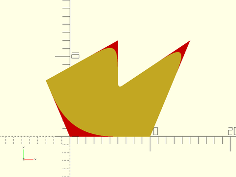
Example 5: Circular rounding, different at every corner, some corners left unrounded
include <BOSL2/std.scad>
include <BOSL2/rounding.scad>
shape = [[0,0], [10,0], [15,12], [6,6], [6, 12], [-3,7]];
radii = [1.8, 0, 2, 0.3, 1.2, 0];
polygon(round_corners(shape, radius = radii,$fn=64));
color("red") down(.1) polygon(shape);
Example 6: Continuous curvature rounding, different at every corner, with varying smoothness parameters as well, and $fs set very small. Note that $fa is ignored here with method set to "smooth".
include <BOSL2/std.scad>
include <BOSL2/rounding.scad>
shape = [[0,0], [10,0], [15,12], [6,6], [6, 12], [-3,7]];
cuts = [1.5,0,2,0.3, 1.2, 0];
k = [0.6, 0.5, 0.5, 0.7, 0.3, 0.5];
polygon(round_corners(shape, method="smooth", cut=cuts, k=k, $fs=0.1));
color("red") down(.1) polygon(shape);
Example 7: Chamfers

include <BOSL2/std.scad>
include <BOSL2/rounding.scad>
$fn=36;
shape = [[0,0], [10,0], [15,12], [6,6], [6, 12], [-3,7]];
polygon(round_corners(shape, method="chamfer", cut=1));
color("red") down(.1) polygon(shape);
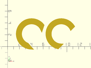
Example 8: 3D printing test pieces to display different curvature shapes. You can see the discontinuity in the curvature on the "C" piece in the rendered image.
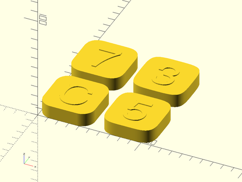
include <BOSL2/std.scad>
include <BOSL2/rounding.scad>
ten = square(50);
cut = 5;
linear_extrude(height=14) {
  translate([25,25,0])text("C",size=30, valign="center", halign="center");
  translate([85,25,0])text("5",size=30, valign="center", halign="center");
  translate([85,85,0])text("3",size=30, valign="center", halign="center");
  translate([25,85,0])text("7",size=30, valign="center", halign="center");
}
linear_extrude(height=13) {
  polygon(round_corners(ten, cut=cut, $fn=96*4));
  translate([60,0,0])polygon(round_corners(ten,  method="smooth", cut=cut, $fn=96));
  translate([60,60,0])polygon(round_corners(ten, method="smooth", cut=cut, k=0.32, $fn=96));
  translate([0,60,0])polygon(round_corners(ten, method="smooth", cut=cut, k=0.7, $fn=96));
}
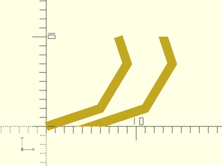
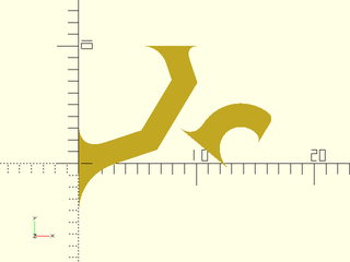
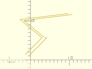
Example 9: Rounding a path that is not closed in a three different ways.
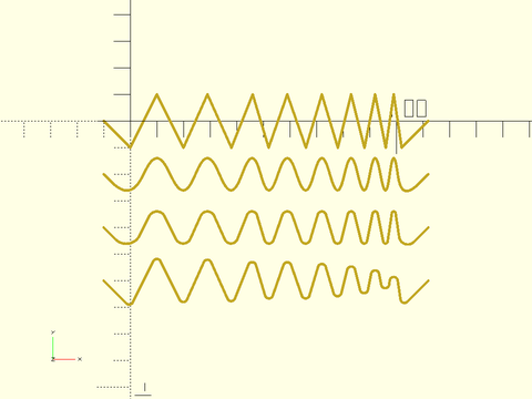
include <BOSL2/std.scad>
include <BOSL2/rounding.scad>
$fs=.1;
$fa=1;
zigzagx = [-10, 0, 10, 20, 29, 38, 46, 52, 59, 66, 72, 78, 83, 88, 92, 96, 99, 102, 112];
zigzagy = concat([0], flatten(repeat([-10,10],8)), [-10,0]);
zig = hstack(zigzagx,zigzagy);
stroke(zig,width=1);   // Original shape
fwd(20)            // Smooth size corners with a cut of 4 and curvature parameter 0.6
  stroke(round_corners(zig,cut=4, k=0.6, method="smooth", closed=false),width=1);
fwd(40)            // Smooth size corners with circular arcs and a cut of 4
  stroke(round_corners(zig,cut=4,closed=false, method="circle"),width=1);
                   // Smooth size corners with a circular arc and radius 1.5 (close to maximum possible)
fwd(60)            // Note how the different points are cut back by different amounts
  stroke(round_corners(zig,radius=1.5,closed=false),width=1);
Example 10: Rounding some random 3D paths
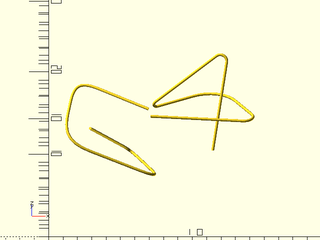
include <BOSL2/std.scad>
include <BOSL2/rounding.scad>
$fn=36;
list1= [
  [2.887360, 4.03497, 6.372090],
  [5.682210, 9.37103, 0.783548],
  [7.808460, 4.39414, 1.843770],
  [0.941085, 5.30548, 4.467530],
  [1.860540, 9.81574, 6.497530],
  [6.938180, 7.21163, 5.794530]
];
list2= [
  [1.079070, 4.74091, 6.900390],
  [8.775850, 4.42248, 6.651850],
  [5.947140, 9.17137, 6.156420],
  [0.662660, 6.95630, 5.884230],
  [6.564540, 8.86334, 9.953110],
  [5.420150, 4.91874, 3.866960]
];
path_sweep(regular_ngon(n=36,or=.1),round_corners(list1,closed=false, method="smooth", cut = 0.65));
right(6)
  path_sweep(regular_ngon(n=36,or=.1),round_corners(list2,closed=false, method="circle", cut = 0.75));
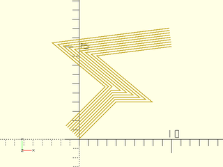
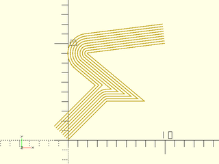
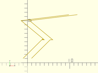
Example 11: Rounding a spiral with increased rounding along the length
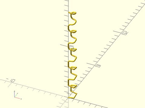
include <BOSL2/std.scad>
include <BOSL2/rounding.scad>
// Construct a square spiral path in 3D
$fn=36;
square = [[0,0],[1,0],[1,1],[0,1]];
spiral = flatten(repeat(concat(square,reverse(square)),5));  // Squares repeat 10x, forward and backward
squareind = [for(i=[0:9]) each [i,i,i,i]];                   // Index of the square for each point
z = count(40)*.2+squareind;
path3d = hstack(spiral,z);                                   // 3D spiral
rounding = squareind/20;
    // Setting k=1 means curvature won't be continuous, but curves are as round as possible
    // Try changing the value to see the effect.
rpath = round_corners(path3d, joint=rounding, k=1, method="smooth", closed=false);
path_sweep( regular_ngon(n=36, or=.1), rpath);
Example 12: The rounding invocation that is commented out gives an error because the rounding parameters interfere with each other. The error message gives a list of factors that can help you fix this: [0.852094, 0.852094, 1.85457, 10.1529]
include <BOSL2/std.scad>
include <BOSL2/rounding.scad>
$fn=64;
path = [[0, 0],[10, 0],[20, 20],[30, -10]];
debug_polygon(path);
//polygon(round_corners(path,cut = [1,3,1,1],
//        method="circle"));
Example 13: The list of factors shows that the problem is in the first two rounding values, because the factors are smaller than one. If we multiply the first two parameters by 0.85 then the roundings fit. The verbose option gives us the same fit factors.

include <BOSL2/std.scad>
include <BOSL2/rounding.scad>
$fn=64;
path = [[0, 0],[10, 0],[20, 20],[30, -10]];
polygon(round_corners(path,cut = [0.85,3*0.85,1,1],
                      method="circle", verbose=true));
Example 14: From the fit factors we can see that rounding at vertices 2 and 3 could be increased a lot. Applying those factors we get this more rounded shape. The new fit factors show that we can still further increase the rounding parameters if we wish.
include <BOSL2/std.scad>
include <BOSL2/rounding.scad>
$fn=64;
path = [[0, 0],[10, 0],[20, 20],[30, -10]];
polygon(round_corners(path,cut = [0.85,3*0.85,2.13, 10.15],
                      method="circle",verbose=true));
Example 15: Using the joint parameter it's easier to understand whether your roundvers will fit. We can guarantee a fairly large roundover on any path by picking each one to use up half the segment distance along the shorter of its two segments:
include <BOSL2/std.scad>
include <BOSL2/rounding.scad>
$fn=64;
path = [[0, 0],[10, 0],[20, 20],[30, -10]];
path_len = path_segment_lengths(path,closed=true);
halflen = [for(i=idx(path)) min(select(path_len,i-1,i))/2];
polygon(round_corners(path,joint = halflen,
                      method="circle",verbose=true));
Example 16: Chamfering, specifying the chamfer width
include <BOSL2/std.scad>
include <BOSL2/rounding.scad>
path = star(5, step=2, d=100);
path2 = round_corners(path, method="chamfer", width=5);
polygon(path2);
Example 17: Chamfering, specifying the cut
include <BOSL2/std.scad>
include <BOSL2/rounding.scad>
path = star(5, step=2, d=100);
path2 = round_corners(path, method="chamfer", cut=5);
polygon(path2);
Example 18: Chamfering, specifying joint length
include <BOSL2/std.scad>
include <BOSL2/rounding.scad>
path = star(5, step=2, d=100);
path2 = round_corners(path, method="chamfer", joint=5);
polygon(path2);
Example 19: Two passes to apply chamfers first, and then round the unchamfered corners. Chamfers always add one point, so it's not hard to keep track of the vertices
include <BOSL2/std.scad>
include <BOSL2/rounding.scad>
$fn=32;
shape = square(10);
chamfered = round_corners(shape, method="chamfer",
                          cut=[2,0,2,0]);
rounded = round_corners(chamfered,
           cut = [0, 0,  // 1st original vertex, chamfered
                  1.5,   // 2nd original vertex
                  0, 0,  // 3rd original vertex, chamfered
                  2.5]); // 4th original vertex
polygon(rounded);
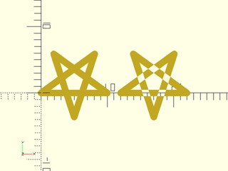
Example 20: Another example of mixing chamfers and roundings with two passes
include <BOSL2/std.scad>
include <BOSL2/rounding.scad>
path = star(5, step=2, d=100);
chamfcut = [for (i=[0:4]) each [7,0]];
radii = [for (i=[0:4]) each [0,0,10]];
path2=round_corners(
        round_corners(path,
                      method="chamfer",
                      cut=chamfcut),
        radius=radii);
stroke(path2, closed=true);
Example 21: Specifying by corner index. Use list_set() to construct the full chamfer cut list.

include <BOSL2/std.scad>
include <BOSL2/rounding.scad>
path = star(47, ir=25, or=50);  // long path, lots of corners
chamfind = [8, 28, 60];         // But only want 3 chamfers
chamfcut = list_set([],chamfind,[10,13,15],minlen=len(path));
rpath = round_corners(path, cut=chamfcut, method="chamfer");
polygon(rpath);
Example 22: Two-pass to chamfer and round by index. Use repeat_entries() to correct for first pass chamfers.

include <BOSL2/std.scad>
include <BOSL2/rounding.scad>
$fn=32;
path = star(47, ir=32, or=65);  // long path, lots of corners
chamfind = [8, 28, 60];         // But only want 3 chamfers
roundind = [7,9,27,29,59,61];   // And 6 roundovers
chamfcut = list_set([],chamfind,[10,13,15],minlen=len(path));
roundcut = list_set([],roundind,repeat(8,6),minlen=len(path));
dups = list_set([], chamfind, repeat(2,len(chamfind)), dflt=1, minlen=len(path));
rpath1 = round_corners(path, cut=chamfcut, method="chamfer");
rpath2 = round_corners(rpath1, cut=repeat_entries(roundcut,dups));
polygon(rpath2);
Synopsis: Create smoothed path that passes through all the points of a given path. [Path]
See Also: round_corners(), path_join(), offset_stroke()
Usage:
- smoothed = smooth_path(path, [tangents], [size=|relsize=], [splinesteps=], [closed=], [uniform=]);
Description:
Smooths the input path using a cubic spline. Every segment of the path will be replaced by a cubic curve
with splinesteps points. The cubic interpolation will pass through every input point on the path
and will match the tangents at every point. If you do not specify tangents they will be computed using
path_tangents with uniform=false by default. Note that setting uniform to true with non-uniform
sampling may be desirable in some cases but tends to produces curves that overshoot the point on the path.
The size or relsize parameter determines how far the curve can bend away from the input path. In the case where the curve has a single hump, the size specifies the exact distance between the specified path and the curve. If you give relsize then it is relative to the segment length (e.g. 0.05 means 5% of the segment length). In 2d when the spline may make an S-curve, in which case the size parameter specifies the sum of the deviations of the two peaks of the curve. In 3-space the bezier curve may have three extrema: two maxima and one minimum. In this case the size specifies the sum of the maxima minus the minimum. At a given segment there is a maximum size: if your size value is too large it will be rounded down. See also path_to_bezpath().
Arguments:
| By Position | What it does |
|---|---|
path |
path to smooth |
tangents |
tangents constraining curve direction at each point. Default: computed automatically |
| By Name | What it does |
|---|---|
relsize |
relative size specification for the curve, a number or vector. Default: 0.1 |
size |
absolute size specification for the curve, a number or vector |
uniform |
set to true to compute tangents with uniform=true. Default: false |
closed |
true if the curve is closed. Default: false. |
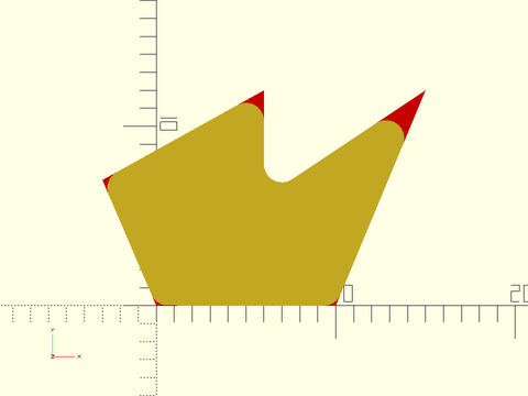
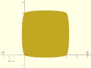
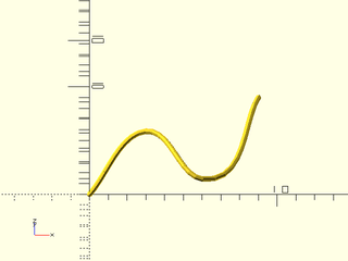
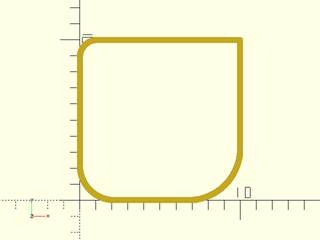
Example 1: Original path in green, smoothed path in yellow:
include <BOSL2/std.scad>
include <BOSL2/rounding.scad>
color("green")stroke(square(4), width=0.1);
stroke(smooth_path(square(4),size=0.4), width=0.1);
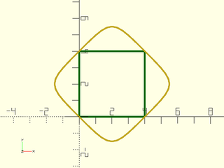
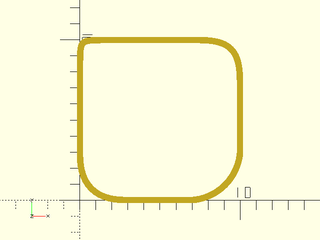
Example 2: Closing the path changes the end tangents
include <BOSL2/std.scad>
include <BOSL2/rounding.scad>
polygon(smooth_path(square(4),size=0.4,closed=true));
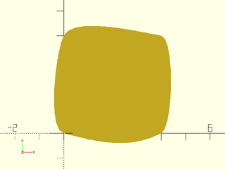
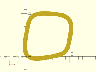
Example 3: Turning on uniform tangent calculation also changes the end derivatives:
include <BOSL2/std.scad>
include <BOSL2/rounding.scad>
color("green")stroke(square(4), width=0.1);
stroke(smooth_path(square(4),size=0.4,uniform=true),
       width=0.1);
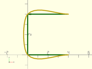
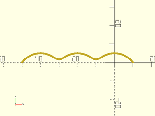
Example 4: Here's a wide rectangle. Using size means all edges bulge the same amount, regardless of their length.
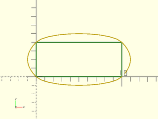
include <BOSL2/std.scad>
include <BOSL2/rounding.scad>
color("green")
  stroke(square([10,4]), closed=true, width=0.1);
stroke(smooth_path(square([10,4]),size=1,closed=true),
       width=0.1);
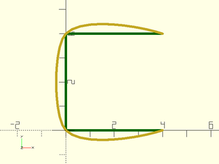
Example 5: With relsize the bulge is proportional to the side length.
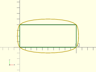
include <BOSL2/std.scad>
include <BOSL2/rounding.scad>
color("green")stroke(square([10,4]), closed=true, width=0.1);
stroke(smooth_path(square([10,4]),relsize=0.1,closed=true),
       width=0.1);
Example 6: Settting uniform to true biases the tangents to aline more with the line sides
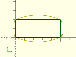
include <BOSL2/std.scad>
include <BOSL2/rounding.scad>
color("green")
  stroke(square([10,4]), closed=true, width=0.1);
stroke(smooth_path(square([10,4]),uniform=true,
                   relsize=0.1,closed=true),
       width=0.1);
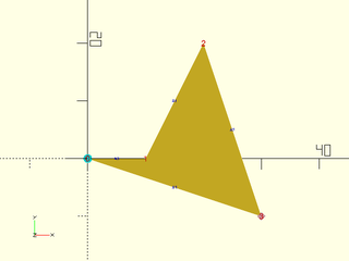
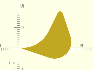
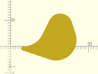
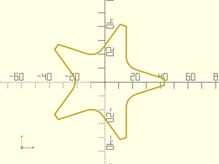
Example 7: A more interesting shape:
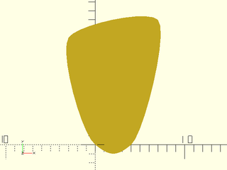
include <BOSL2/std.scad>
include <BOSL2/rounding.scad>
path = [[0,0], [4,0], [7,14], [-3,12]];
polygon(smooth_path(path,size=1,closed=true));
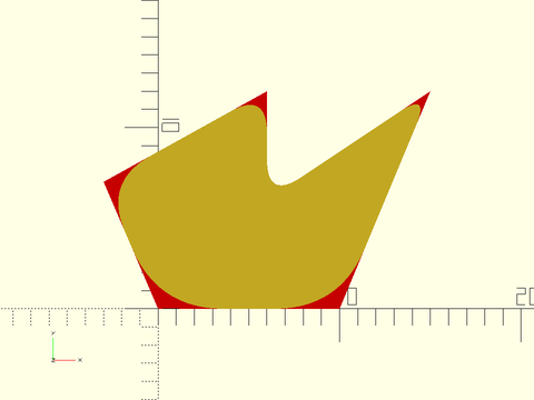
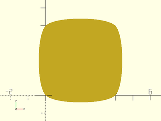
Example 8: Here's the square again with less smoothing.
include <BOSL2/std.scad>
include <BOSL2/rounding.scad>
polygon(smooth_path(square(4), size=.25,closed=true));
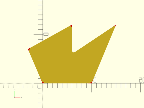
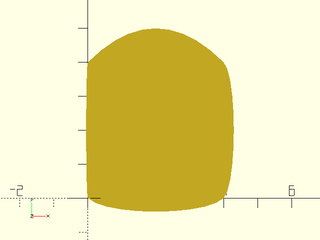
Example 9: Here's the square with a size that's too big to achieve, so you get the maximum possible curve:
include <BOSL2/std.scad>
include <BOSL2/rounding.scad>
color("green")stroke(square(4), width=0.1,closed=true);
stroke(smooth_path(square(4), size=4, closed=true),
       closed=true,width=.1);
Example 10: You can alter the shape of the curve by specifying your own arbitrary tangent values
include <BOSL2/std.scad>
include <BOSL2/rounding.scad>
polygon(smooth_path(square(4),
        tangents=1.25*[[-2,-1], [-4,1], [1,2], [6,-1]],
        size=0.4,closed=true));
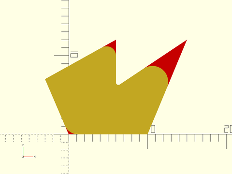
Example 11: Or you can give a different size for each segment
include <BOSL2/std.scad>
include <BOSL2/rounding.scad>
polygon(smooth_path(square(4),size = [.4, .05, 1, .3],
                    closed=true));
Example 12: Works on 3d paths as well
include <BOSL2/std.scad>
include <BOSL2/rounding.scad>
path = [[0,0,0],[3,3,2],[6,0,1],[9,9,0]];
stroke(smooth_path(path,relsize=.1),width=.3);
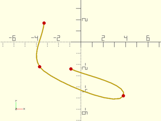
Example 13: This shows the type of overshoot that can occur with uniform=true. You can produce overshoots like this if you supply a tangent that is difficult to connect to the adjacent points
include <BOSL2/std.scad>
include <BOSL2/rounding.scad>
pts = [[-3.3, 1.7], [-3.7, -2.2], [3.8, -4.8], [-0.9, -2.4]];
stroke(smooth_path(pts, uniform=true, relsize=0.1),width=.1);
color("red")move_copies(pts)circle(r=.15,$fn=12);
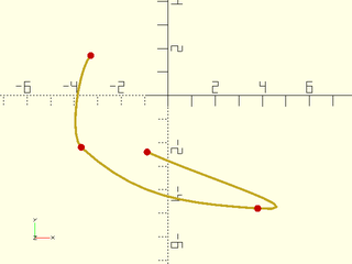
Example 14: With the default of uniform false no overshoot occurs. Note that the shape of the curve is quite different.
include <BOSL2/std.scad>
include <BOSL2/rounding.scad>
pts = [[-3.3, 1.7], [-3.7, -2.2], [3.8, -4.8], [-0.9, -2.4]];
stroke(smooth_path(pts, uniform=false, relsize=0.1),width=.1);
color("red")move_copies(pts)circle(r=.15,$fn=12);
Synopsis: Join paths end to end with optional rounding. [Path]
See Also: round_corners(), smooth_path(), offset_stroke()
Usage:
- joined_path = path_join(paths, [joint], [k=], [relocate=], [closed=]);
Description:
Connect a sequence of paths together into a single path with optional continuous curvature rounding
applied at the joints. By default the first path is taken as specified and subsequent paths are
translated into position so that each path starts where the previous path ended.
If you set relocate to false then this relocation is skipped.
You specify rounding using the joint parameter, which specifies the distance away from the corner
where the roundover should start. The path_join function may remove many path points to cut the path
back by the joint length. Rounding is using continous curvature 4th order bezier splines and
the parameter k specifies how smooth the curvature match is. This parameter ranges from 0 to 1 with
a default of 0.5. Use a larger k value to get a curve that is bigger for the same joint value. When
k=1 the curve may be similar to a circle if your curves are symmetric. As the path is built up, the joint
parameter applies to the growing path, so if you pick a large joint parameter it may interact with the
previous path sections. See Types of Roundover for more details
on continuous curvature rounding.
The rounding is created by extending the two clipped paths to define a corner point. If the extensions of the paths do not intersect, the function issues an error. When closed=true the final path should actually close the shape, repeating the starting point of the shape. If it does not, then the rounding will fill the gap.
The number of segments in the roundovers is set based on $fn and $fs. If you use $fn it specifies the number of segments in the roundover, regardless of its angular extent.
Arguments:
| By Position | What it does |
|---|---|
paths |
list of paths to join |
joint |
joint distance, either a number, a pair (giving the previous and next joint distance) or a list of numbers and pairs. Default: 0 |
| By Name | What it does |
|---|---|
k |
curvature parameter, either a number or vector. Default: 0.5 |
relocate |
set to false to prevent paths from being arranged tail to head. Default: true |
closed |
set to true to round the junction between the last and first paths. Default: false |
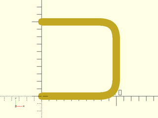
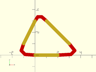
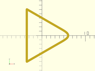
Example 1: Connection of 3 simple paths.
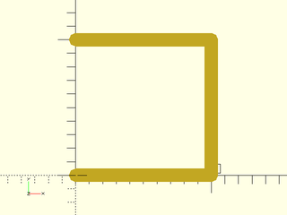
include <BOSL2/std.scad>
include <BOSL2/rounding.scad>
horiz = [[0,0],[10,0]];
vert = [[0,0],[0,10]];
stroke(path_join([horiz, vert, -horiz]));
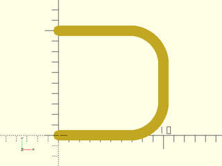
Example 2: Adding curvature with joint of 3
include <BOSL2/std.scad>
include <BOSL2/rounding.scad>
horiz = [[0,0],[10,0]];
vert = [[0,0],[0,10]];
stroke(path_join([horiz, vert, -horiz],joint=3,$fn=16));
Example 3: Setting k=1 increases the amount of curvature
include <BOSL2/std.scad>
include <BOSL2/rounding.scad>
horiz = [[0,0],[10,0]];
vert = [[0,0],[0,10]];
stroke(path_join([horiz, vert, -horiz],joint=3,k=1,$fn=16));
Example 4: Specifying pairs of joint values at a path joint creates an asymmetric curve
include <BOSL2/std.scad>
include <BOSL2/rounding.scad>
horiz = [[0,0],[10,0]];
vert = [[0,0],[0,10]];
stroke(path_join([horiz, vert, -horiz],
                 joint=[[4,1],[1,4]],$fn=16),width=.3);
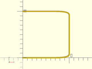
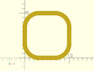
Example 5: A closed square
include <BOSL2/std.scad>
include <BOSL2/rounding.scad>
horiz = [[0,0],[10,0]];
vert = [[0,0],[0,10]];
stroke(path_join([horiz, vert, -horiz, -vert],
                 joint=3,k=1,closed=true,$fn=16),closed=true);
Example 6: Different curve at each corner by changing the joint size
include <BOSL2/std.scad>
include <BOSL2/rounding.scad>
horiz = [[0,0],[10,0]];
vert = [[0,0],[0,10]];
stroke(path_join([horiz, vert, -horiz, -vert],
                 joint=[3,0,1,2],k=1,closed=true,$fn=16),
       closed=true,width=0.4);
Example 7: Different curve at each corner by changing the curvature parameter. Note that k=0 still gives a small curve, unlike joint=0 which gives a sharp corner.
include <BOSL2/std.scad>
include <BOSL2/rounding.scad>
horiz = [[0,0],[10,0]];
vert = [[0,0],[0,10]];
stroke(path_join([horiz, vert, -horiz, -vert],joint=3,
                 k=[1,.5,0,.7],closed=true,$fn=16),
       closed=true,width=0.4);
Example 8: Joint value of 7 is larger than half the square so curves interfere with each other, which breaks symmetry because they are computed sequentially
include <BOSL2/std.scad>
include <BOSL2/rounding.scad>
horiz = [[0,0],[10,0]];
vert = [[0,0],[0,10]];
stroke(path_join([horiz, vert, -horiz, -vert],joint=7,
                  k=.4,closed=true,$fn=16),
       closed=true);
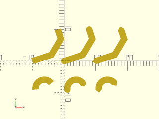
Example 9: Unlike round_corners, we can add curves onto curves.
include <BOSL2/std.scad>
include <BOSL2/rounding.scad>
$fn=64;
myarc = arc(width=20, thickness=5 );
stroke(path_join(repeat(myarc,3), joint=4));
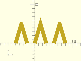
Example 10: Here we make a closed shape from two arcs and round the sharp tips
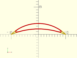
include <BOSL2/std.scad>
include <BOSL2/rounding.scad>
arc1 = arc(width=20, thickness=4,$fn=75);
arc2 = reverse(arc(width=20, thickness=2,$fn=75));
// Without rounding
stroke(path_join([arc1,arc2]),width=.3);
// With rounding
color("red")stroke(path_join([arc1,arc2], 3,k=1,closed=true),
                   width=.3,closed=true,$fn=12);
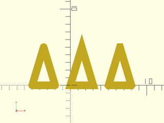
Example 11: Combining arcs with segments
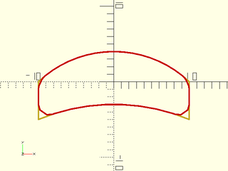
include <BOSL2/std.scad>
include <BOSL2/rounding.scad>
arc1 = arc(width=20, thickness=4,$fn=75);
arc2 = reverse(arc(width=20, thickness=2,$fn=75));
vpath = [[0,0],[0,-5]];
stroke(path_join([arc1,vpath,arc2,reverse(vpath)]),width=.2);
color("red")stroke(path_join([arc1,vpath,arc2,reverse(vpath)],
                             [1,2,2,1],k=1,closed=true),
                   width=.2,closed=true,$fn=12);
Example 12: Here relocation is off. We have three segments (in yellow) and add the curves to the segments. Notice that joint zero still produces a curve because it refers to the endpoints of the supplied paths.
include <BOSL2/std.scad>
include <BOSL2/rounding.scad>
p1 = [[0,0],[2,0]];
p2 = [[3,1],[1,3]];
p3 = [[0,3],[-1,1]];
color("red")stroke(
  path_join([p1,p2,p3], joint=0, relocate=false,
            closed=true),
  width=.3,$fn=48);
for(x=[p1,p2,p3]) stroke(x,width=.3);
Example 13: If you specify closed=true when the last path doesn't meet the first one then it is similar to using relocate=false: the function tries to close the path using a curve. In the example below, this results in a long curve to the left, when given the unclosed three segments as input. Note that if the segments are parallel the function fails with an error. The extension of the curves must intersect in a corner for the rounding to be well-defined. To get a normal rounding of the closed shape, you must include a fourth path, the last segment that closes the shape.
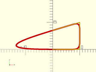
include <BOSL2/std.scad>
include <BOSL2/rounding.scad>
horiz = [[0,0],[10,0]];
vert = [[0,0],[0,10]];
h2 = [[0,-3],[10,0]];
color("red")stroke(
  path_join([horiz, vert, -h2],closed=true,
            joint=3,$fn=25),
  closed=true,width=.5);
stroke(path_join([horiz, vert, -h2]),width=.3);
Example 14: With a single path with closed=true the start and end junction is rounded.
include <BOSL2/std.scad>
include <BOSL2/rounding.scad>
tri = regular_ngon(n=3, r=7);
stroke(path_join([tri], joint=3,closed=true,$fn=12),
       closed=true,width=.5);
Synopsis: Draws a line along a path with options to specify angles and roundings at the ends. [Path] [Region]
See Also: round_corners(), smooth_path(), path_join()
Usage: as module
- offset_stroke(path, [width], [rounded=], [chamfer=], [start=], [end=], [check_valid=], [quality=], [closed=],...) [ATTACHMENTS];
Usage: as function
- path = offset_stroke(path, [width], closed=false, [rounded=], [chamfer=], [start=], [end=], [check_valid=], [quality=],...);
- region = offset_stroke(path, [width], closed=true, [rounded=], [chamfer=], [start=], [end=], [check_valid=], [quality=],...);
Description:
Uses offset() to compute a stroke for the input path. Unlike stroke, the result does not need to be
centered on the input path. The corners can be rounded, pointed, or chamfered, and you can make the ends
rounded, flat or pointed with the start and end parameters.
The check_valid and quality parameters are passed through to offset()
If width is a scalar then the output will be a centered stroke of the specified width. If width
is a list of two values then those two values will define the stroke side positions relative to the center line, where
as with offset(), the shift is to the left for open paths and outward for closed paths. For example,
setting width to [0,1] will create a stroke of width 1 that extends entirely to the left of the input, and and [-4,-6]
will create a stroke of width 2 offset 4 units to the right of the input path.
If closed==false then the function form will return a path. If closed==true then it will return a region. The start and
end parameters are forbidden for closed paths.
Three simple end treatments are supported, "flat" (the default), "round" and "pointed". The "flat" treatment cuts off the ends perpendicular to the path and the "round" treatment applies a semicircle to the end. The "pointed" end treatment caps the stroke with a centered triangle that has 45 degree angles on each side.
More complex end treatments are available through parameter lists with helper functions to ease parameter passing. The parameter list keywords are
- "for" : must appear first in the list and have the value "offset_stroke"
- "type": the type of end treatment, one of "shifted_point", "roundover", or "flat"
- "angle": relative angle (relative to the path)
- "abs_angle": absolute angle (angle relative to x-axis)
- "cut": cut distance for roundovers, a single value to round both corners identically or a list of two values for the two corners. Negative values round outward.
- "k": curvature smoothness parameter for roundovers, default 0.75
Function helpers for defining ends, prefixed by "os" for offset_stroke, are:
- os_flat(angle|absangle): specify a flat end either relative to the path or relative to the x-axis
- os_pointed(dist, [loc]): specify a pointed tip where the point is distance
locfrom the centerline (positive is the left direction as for offset), anddistis the distance from the path end to the point tip. The default value forlocis zero (the center). You must specifydistwhen using this option. - os_round(cut, [angle|absangle], [k]). Rounded ends with the specified cut distance, based on the specified angle or absolute angle. The
kparameter is the smoothness parameter for continuous curvature rounding. See Types of Roundover for more details on continuous curvature rounding.
Note that offset_stroke() will attempt to apply roundovers and angles at the ends even when it means deleting segments of the stroke, unlike round_corners which only works on a segment adjacent to a corner. If you specify an overly extreme angle it will fail to find an intersection with the stroke and display an error. When you specify an angle the end segment is rotated around the center of the stroke and the last segment of the stroke one one side is extended to the corner.
The $fn and $fs variables are used in the usual way to determine the number of segments for roundings produced by the offset
invocations and roundings produced by the semi-circular "round" end treatment. The os_round() end treatment
uses a bezier curve, and will produce segments of approximate length $fs or it will produce $fn segments.
(This means that even a quarter circle will have $fn segments, unlike the usual case where it would have $fn/4 segments.)
Arguments:
| By Position | What it does |
|---|---|
path |
2d path that defines the stroke |
width |
width of the stroke, a scalar or a vector of 2 values giving the offset from the path. Default: 1 |
| By Name | What it does |
|---|---|
rounded |
set to true to use rounded offsets, false to use sharp (delta) offsets. Default: true |
chamfer |
set to true to use chamfers when rounded=false. Default: false |
start |
end treatment for the start of the stroke when closed=false. See above for details. Default: "flat" |
end |
end treatment for the end of the stroke when closed=false. See above for details. Default: "flat" |
check_valid |
passed to offset(). Default: true |
quality |
passed to offset(). Default: 1 |
closed |
true if the curve is closed, false otherwise. Default: false |
anchor |
Translate so anchor point is at origin (0,0,0). See anchor. Default: "origin"
|
spin |
Rotate this many degrees after anchor. See spin. Default: 0
|
cp |
Centerpoint for determining intersection anchors or centering the shape. Determintes the base of the anchor vector. Can be "centroid", "mean", "box" or a 2D point. Default: "centroid" |
atype |
Set to "hull" or "intersect" to select anchor type. Default: "hull" |
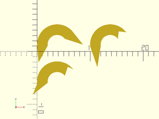
Example 1: Basic examples illustrating flat, round, and pointed ends, on a finely sampled arc and a path made from 3 segments.
include <BOSL2/std.scad>
include <BOSL2/rounding.scad>
arc = arc(points=[[1,1],[3,4],[6,3]],n=50);
path = [[0,0],[6,2],[9,7],[8,10]];
xdistribute(spacing=10){
  offset_stroke(path, width = 2);
  offset_stroke(path, start="round", end="round", width = 2, $fn=32);
  offset_stroke(path, start="pointed", end="pointed", width = 2);
}
fwd(10) xdistribute(spacing=10){
  offset_stroke(arc, width = 2);
  offset_stroke(arc, start="round", end="round", width = 2, $fn=32);
  offset_stroke(arc, start="pointed", end="pointed", width = 2);
}
Example 2: The effect of the rounded and chamfer options is most evident at sharp corners. This only affects the middle of the path, not the ends.
include <BOSL2/std.scad>
include <BOSL2/rounding.scad>
sharppath = [[0,0], [1.5,5], [3,0]];
xdistribute(spacing=5){
  offset_stroke(sharppath, $fn=16);
  offset_stroke(sharppath, rounded=false);
  offset_stroke(sharppath, rounded=false, chamfer=true);
}
Example 3: When closed is enabled all the corners are affected by those options.
include <BOSL2/std.scad>
include <BOSL2/rounding.scad>
sharppath = [[0,0], [1.5,5], [3,0]];
xdistribute(spacing=5){
  offset_stroke(sharppath,closed=true, $fn=16);
  offset_stroke(sharppath, rounded=false, closed=true);
  offset_stroke(sharppath, rounded=false, chamfer=true,
                closed=true);
}
Example 4: The left stroke uses flat ends with a relative angle of zero. The right hand one uses flat ends with an absolute angle of zero, so the ends are parallel to the x-axis.
include <BOSL2/std.scad>
include <BOSL2/rounding.scad>
path = [[0,0],[6,2],[9,7],[8,10]];
offset_stroke(path, start=os_flat(angle=0), end=os_flat(angle=0));
right(5)
  offset_stroke(path, start=os_flat(abs_angle=0), end=os_flat(abs_angle=0));
Example 5: With continuous sampling the end treatment can remove segments or extend the last segment linearly, as shown here. Again the left side uses relative angle flat ends and the right hand example uses absolute angle.
include <BOSL2/std.scad>
include <BOSL2/rounding.scad>
arc = arc(points=[[4,0],[3,4],[6,3]],n=50);
offset_stroke(arc, start=os_flat(angle=45), end=os_flat(angle=45));
right(5)
  offset_stroke(arc, start=os_flat(abs_angle=45), end=os_flat(abs_angle=45));
Example 6: The os_pointed() end treatment allows adjustment of the point tip, as shown here. The width is 2 so a location of 1 is at the edge.
include <BOSL2/std.scad>
include <BOSL2/rounding.scad>
arc = arc(points=[[1,1],[3,4],[6,3]],n=50);
offset_stroke(arc, width=2, start=os_pointed(loc=1,dist=3),end=os_pointed(loc=1,dist=3));
right(10)
  offset_stroke(arc, width=2, start=os_pointed(dist=4),end=os_pointed(dist=-1));
fwd(7)
  offset_stroke(arc, width=2, start=os_pointed(loc=2,dist=2),end=os_pointed(loc=.5,dist=-1));
Example 7: The os_round() end treatment adds roundovers to the end corners by specifying the cut parameter. In the first example, the cut parameter is the same at each corner. The bezier smoothness parameter k is given to allow a larger cut. In the second example, each corner is given a different roundover, including zero for no rounding at all. The red shows the same strokes without the roundover.
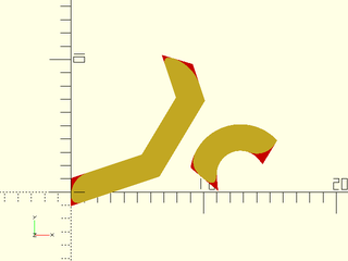
include <BOSL2/std.scad>
include <BOSL2/rounding.scad>
$fn=36;
arc = arc(points=[[1,1],[3,4],[6,3]],n=50);
path = [[0,0],[6,2],[9,7],[8,10]];
offset_stroke(path, width=2, rounded=false,start=os_round(angle=-20, cut=0.4,k=.9),
                                           end=os_round(angle=-35, cut=0.4,k=.9));
color("red")down(.1)offset_stroke(path, width=2, rounded=false,start=os_flat(-20),
                                                               end=os_flat(-35));
right(9){
  offset_stroke(arc, width=2, rounded=false, start=os_round(cut=[.3,.6],angle=-45),
                                             end=os_round(angle=20,cut=[.6,0]));
  color("red")down(.1)offset_stroke(arc, width=2, rounded=false, start=os_flat(-45),
                                                                 end=os_flat(20));
}
Example 8: Negative cut values produce a flaring end. Note how the absolute angle aligns the ends of the first example withi the axes. In the second example positive and negative cut values are combined. Note also that very different cuts are needed at the start end to produce a similar looking flare.
include <BOSL2/std.scad>
include <BOSL2/rounding.scad>
arc = arc(points=[[1,1],[3,4],[6,3]],n=50);
path = [[0,0],[6,2],[9,7],[8,10]];
offset_stroke(path, width=2, rounded=false,start=os_round(cut=-1, abs_angle=90),
                                           end=os_round(cut=-0.5, abs_angle=0),$fn=36);
right(10)
   offset_stroke(arc, width=2, rounded=false, start=os_round(cut=[-.75,-.2], angle=-45),
                                              end=os_round(cut=[-.2,.2], angle=20),$fn=36);
Example 9: Setting the width to a vector allows you to offset the stroke. Here with successive increasing offsets we create a set of parallel strokes
include <BOSL2/std.scad>
include <BOSL2/rounding.scad>
path = [[0,0],[4,4],[8,4],[2,9],[10,10]];
for(i=[0:.25:2])
  offset_stroke(path, rounded=false,width = [i,i+.08]);
Example 10: Setting rounded=true in the above example makes a very big difference in the result.
include <BOSL2/std.scad>
include <BOSL2/rounding.scad>
path = [[0,0],[4,4],[8,4],[2,9],[10,10]];
for(i=[0:.25:2])
  offset_stroke(path, rounded=true,width = [i,i+.08], $fn=36);
Example 11: In this example a spurious triangle appears. This results from overly enthusiastic validity checking. Turning validity checking off fixes it in this case.
include <BOSL2/std.scad>
include <BOSL2/rounding.scad>
path = [[0,0],[4,4],[8,4],[2,9],[10,10]];
offset_stroke(path, check_valid=true,rounded=false,
              width = [1.4, 1.5]);
right(2)
  offset_stroke(path, check_valid=false,rounded=false,
                width = [1.4, 1.5]);
Example 12: But in this case, disabling the validity check produces an invalid result.
include <BOSL2/std.scad>
include <BOSL2/rounding.scad>
path = [[0,0],[4,4],[8,4],[2,9],[10,10]];
offset_stroke(path, check_valid=true,rounded=false,
              width = [1.9, 2]);
translate([1,-0.25])
  offset_stroke(path, check_valid=false,rounded=false,
                width = [1.9, 2]);
Example 13: Self-intersecting paths are handled differently than with the stroke() module.
include <BOSL2/std.scad>
include <BOSL2/rounding.scad>
$fn=16;
path = turtle(["move",10,"left",144], repeat=4);
stroke(path, closed=true);
right(12)
  offset_stroke(path, width=1, closed=true);
Synopsis: Make a solid from a polygon with offset that changes along its length. [Geom] [VNF]
See Also: convex_offset_extrude(), rounded_prism(), bent_cutout_mask(), join_prism(), linear_sweep()
Usage: most common module arguments. See Arguments list below for more.
- offset_sweep(path, [height|length=|h=|l=], [bottom], [top], [offset=], [convexity=],...) [ATTACHMENTS];
Usage: most common function arguments. See Arguments list below for more.
- vnf = offset_sweep(path, [height|length=|h=|l=], [bottom], [top], [offset=], ...);
Description:
Takes a 2d path as input and extrudes it upwards and/or downward. Each layer in the extrusion is produced using offset() to expand or shrink the previous layer. When invoked as a function returns a VNF; when invoked as a module produces geometry.
Using the top and/or bottom arguments you can specify a sequence of offsets values, or you can use several built-in offset profiles that
provide end treatments such as roundovers.
The height of the resulting object can be specified using the height argument, in which case height must be larger than the combined height
of the end treatments. If you omit height then the object height will be the height of just the top and bottom end treatments.
The path is shifted by offset() multiple times in sequence
to produce the final shape (not multiple shifts from one parent), so coarse definition of the input path will degrade
from the successive shifts. If the result seems rough or strange try increasing the number of points you use for
your input. If you get unexpected corners in your result you may have forgotten to set $fn or $fa and $fs.
Be aware that large numbers of points (especially when check_valid is true) can lead to lengthy run times. If your
shape doesn't develop new corners from the offsetting you may be able to save a lot of time by setting check_valid=false. Be aware that
disabling the validity check when it is needed can generate invalid polyhedra that will produce CGAL errors upon
rendering. Such validity errors will also occur if you specify a self-intersecting shape.
The offset profile is quantized to 1/1024 steps to avoid failures in offset() that can occur with very tiny offsets.
The build-in profiles are: circular rounding, teardrop rounding, continuous curvature rounding, and chamfer. Also note that when a rounding radius is negative the rounding will flare outwards. The easiest way to specify the profile is by using the profile helper functions. These functions take profile parameters, as well as some general settings and translate them into a profile specification, with error checking on your input. The description below describes the helper functions and the parameters specific to each function. Below that is a description of the generic settings that you can optionally use with all of the helper functions. For more details on the "cut" and "joint" rounding parameters, and on continuous curvature rounding, see Types of Roundover.
- profile: os_profile(points) Define the offset profile with a list of points. The first point must be [0,0] and the roundover should rise in the positive y direction, with positive x values for inward motion (standard roundover) and negative x values for flaring outward. If the y value ever decreases then you might create a self-intersecting polyhedron, which is invalid. Such invalid polyhedra will create cryptic assertion errors when you render your model and it is your responsibility to avoid creating them. Note that the starting point of the profile is the center of the extrusion. If you use a profile as the top it will rise upwards. If you use it as the bottom it will be inverted, and will go downward.
- circle: os_circle(r|cut). Define circular rounding either by specifying the radius or cut distance.
- smooth: os_smooth(cut|joint, [k]). Define continuous curvature rounding, with
cutandjointas for round_corners. The k parameter controls how fast the curvature changes and should be between 0 and 1. - teardrop: os_teardrop(r|cut). Rounding using a 1/8 circle that then changes to a 45 degree chamfer. The chamfer is at the end, and enables the object to be 3d printed without support. The radius gives the radius of the circular part.
- chamfer: os_chamfer([height], [width], [cut], [angle]). Chamfer the edge at desired angle or with desired height and width. You can specify height and width together and the angle will be ignored, or specify just one of height and width and the angle is used to determine the shape. Alternatively, specify "cut" along with angle to specify the cut back distance of the chamfer.
- mask: os_mask(mask, [out]). Create a profile from one of the 2d masking shapes. The
outparameter specifies that the mask should flare outward (like crown molding or baseboard). This is set false by default.
The general settings that you can use with all of the helper functions are mostly used to control how offset_sweep() calls the offset() function.
- extra: Add an extra vertical step of the specified height, to be used for intersections or differences. This extra step will extend the resulting object beyond the height you specify. It is ignored by anchoring. Default: 0
- check_valid: passed to offset(). Default: true
- quality: passed to offset(). Default: 1
- steps: Number of vertical steps to use for the profile. (Not used by os_profile). Default: 16
- offset: Select "round" (r=) or "delta" (delta=) offset types for offset. You can also choose "chamfer" but this leads to exponential growth in the number of vertices with the steps parameter. Default: "round"
Many of the arguments are described as setting "default" values because they establish settings which may be overridden by the top and bottom profile specifications.
You will generally want to use the above helper functions to generate the profiles. The profile specification is a list of pairs of keywords and values, e.g. ["for","offset_sweep","r",12, type, "circle"]. The keywords are
- "for" - must appear first in the list and have the value "offset_sweep"
- "type" - type of rounding to apply, one of "circle", "teardrop", "chamfer", "smooth", or "profile" (Default: "circle")
- "r" - the radius of the roundover, which may be zero for no roundover, or negative to round or flare outward. Default: 0
- "cut" - the cut distance for the roundover or chamfer, which may be negative for flares
- "chamfer_width" - the width of a chamfer
- "chamfer_height" - the height of a chamfer
- "angle" - the chamfer angle, measured from the vertical (so zero is vertical, 90 is horizontal). Default: 45
- "joint" - the joint distance for a "smooth" roundover
- "k" - the curvature smoothness parameter for "smooth" roundovers, a value in [0,1]. Default: 0.75
- "points" - point list for use with the "profile" type
- "extra" - extra height added for unions/differences. This makes the shape taller than the requested height. (Default: 0)
- "check_valid" - passed to offset. Default: true.
- "quality" - passed to offset. Default: 1.
- "steps" - number of vertical steps to use for the roundover. Default: 16.
- "offset" - select "round" (r=), "delta" (delta=), or "chamfer" offset type for offset. Default: "round"
Note that if you set the "offset" parameter to "chamfer" then every exterior corner turns from one vertex into two vertices with
each offset operation. Since the offsets are done one after another, each on the output of the previous one, this leads to
exponential growth in the number of vertices. This can lead to long run times or yield models that
run out of recursion depth and give a cryptic error. Furthermore, the generated vertices are distributed non-uniformly. Generally you
will get a similar or better looking model with fewer vertices using "round" instead of
"chamfer". Use the "chamfer" style offset only in cases where the number of steps is very small or just one (such as when using
the os_chamfer profile type).
Arguments:
| By Position | What it does |
|---|---|
path |
2d path (list of points) to extrude |
height / length / l / h
|
total height (including rounded portions, but not extra sections) of the output. Default: combined height of top and bottom end treatments. |
bottom / bot
|
rounding spec for the bottom end |
top |
rounding spec for the top end. |
| By Name | What it does |
|---|---|
ends |
give a rounding spec that applies to both the top and bottom |
offset |
default offset, "round" or "delta". Default: "round"
|
steps |
default step count. Default: 16 |
quality |
default quality. Default: 1 |
check_valid |
default check_valid. Default: true. |
extra |
default extra height. Default: 0 |
caps |
if false do not create end faces. Can be a boolean vector to control ends independent. (function only) Default: true. |
cut |
default cut value. |
chamfer_width |
default width value for chamfers. |
chamfer_height |
default height value for chamfers. |
angle |
default angle for chamfers. Default: 45 |
joint |
default joint value for smooth roundover. |
k |
default curvature parameter value for "smooth" roundover |
convexity |
convexity setting for use with polyhedron. (module only) Default: 10 |
anchor |
Translate so anchor point is at the origin. Default: "base" |
spin |
Rotate this many degrees around Z axis after anchor. Default: 0 |
orient |
Vector to rotate top towards after spin |
atype |
Select "hull", "intersect", "surf_hull" or "surf_intersect" anchor types. Default: "hull" |
cp |
Centerpoint for determining "intersect" anchors or centering the shape. Determintes the base of the anchor vector. Can be "centroid", "mean", "box" or a 3D point. Default: "centroid" |
Anchor Types:
| Anchor Type | What it is |
|---|---|
| hull | Anchors to the convex hull of the linear sweep of the path, ignoring any end roundings. |
| intersect | Anchors to the surface of the linear sweep of the path, ignoring any end roundings. |
| surf_hull | Anchors to the convex hull of the offset_sweep shape, including end treatments. |
| surf_intersect | Anchors to the surface of the offset_sweep shape, including any end treatments. |
Extra Anchors:
| Anchor Name | Position |
|---|---|
| "base" | Anchor to the base of the shape in its native position, ignoring any "extra" |
| "top" | Anchor to the top of the shape in its native position, ignoring any "extra" |
| "zcenter" | Center shape in the Z direction in the native XY position, ignoring any "extra" |
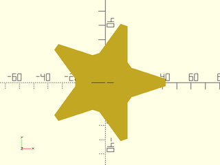
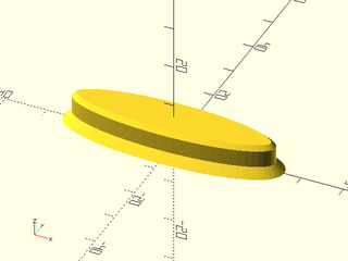
Example 1: Rounding a star shaped prism with postive radius values
include <BOSL2/std.scad>
include <BOSL2/rounding.scad>
star = star(5, r=22, ir=13);
rounded_star = round_corners(star, cut=flatten(repeat([.5,0],5)), $fn=24);
offset_sweep(rounded_star, height=20, bottom=os_circle(r=4), top=os_circle(r=1), steps=15);
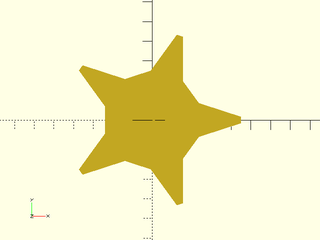
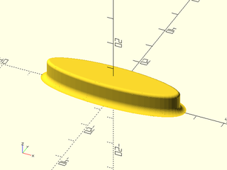
Example 2: Rounding a star shaped prism with negative radius values. The starting shape has no corners, so the value of $fn does not matter.
include <BOSL2/std.scad>
include <BOSL2/rounding.scad>
star = star(5, r=22, ir=13);
rounded_star = round_corners(star, cut=flatten(repeat([.5,0],5)), $fn=36);
offset_sweep(rounded_star, height=20, bottom=os_circle(r=-4), top=os_circle(r=-1), steps=15);
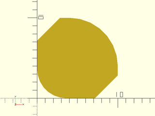
Example 3: If the shape has sharp corners, make sure to set $fn/$fs/$fa. The corners of this triangle are not round, even though offset="round" (the default) because the number of segments is small.

include <BOSL2/std.scad>
include <BOSL2/rounding.scad>
triangle = [[0,0],[10,0],[5,10]];
offset_sweep(triangle, height=6, bottom = os_circle(r=-2),steps=4);
Example 4: Can improve the result by increasing $fn

include <BOSL2/std.scad>
include <BOSL2/rounding.scad>
$fn=12;
triangle = [[0,0],[10,0],[5,10]];
offset_sweep(triangle, height=6, bottom = os_circle(r=-2),steps=4);
Example 5: Using $fa and $fs works too; it produces a different looking triangulation of the rounded corner

include <BOSL2/std.scad>
include <BOSL2/rounding.scad>
$fa=1;$fs=0.3;
triangle = [[0,0],[10,0],[5,10]];
offset_sweep(triangle, height=6, bottom = os_circle(r=-2),steps=4);
Example 6: Here is the star chamfered at the top with a teardrop rounding at the bottom. Check out the rounded corners on the chamfer. The large $fn value ensures a smooth curve on the concave corners of the chamfer. It has no effect anywhere else on the model. Observe how the rounded star points vanish at the bottom in the teardrop: the number of vertices does not remain constant from layer to layer.
include <BOSL2/std.scad>
include <BOSL2/rounding.scad>
star = star(5, r=22, ir=13);
rounded_star = round_corners(star, cut=flatten(repeat([.5,0],5)), $fn=24);
offset_sweep(rounded_star, height=20, bottom=os_teardrop(r=4), top=os_chamfer(width=4),$fn=64);
Example 7: We round a cube using the continous curvature rounding profile. But note that the corners are not smooth because the curved square collapses into a square with corners. When a collapse like this occurs, we cannot turn check_valid off. For a better result use rounded_prism() instead.
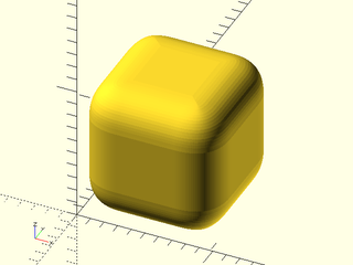
include <BOSL2/std.scad>
include <BOSL2/rounding.scad>
square = square(1);
rsquare = round_corners(square, method="smooth", cut=0.1, k=0.7, $fn=36);
end_spec = os_smooth(cut=0.1, k=0.7, steps=22);
offset_sweep(rsquare, height=1, bottom=end_spec, top=end_spec);
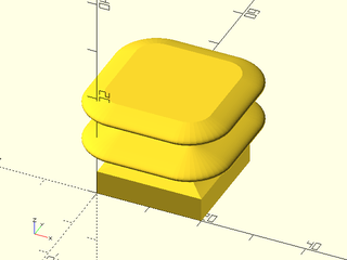
Example 8: A nice rounded box, with a teardrop base and circular rounded interior and top
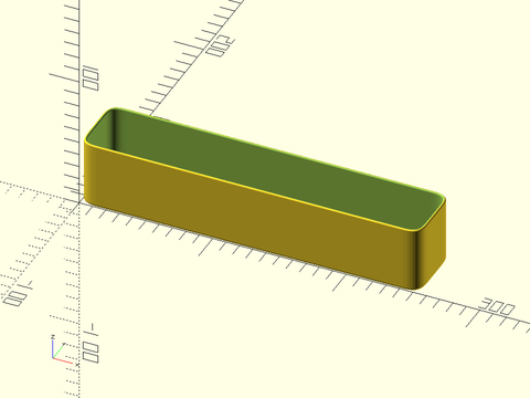
include <BOSL2/std.scad>
include <BOSL2/rounding.scad>
box = square([255,50]);
rbox = round_corners(box, method="smooth", cut=4, $fn=12);
thickness = 2;
difference(){
  offset_sweep(rbox, height=50, check_valid=false, steps=22,
               bottom=os_teardrop(r=2), top=os_circle(r=1));
  up(thickness)
    offset_sweep(offset(rbox, r=-thickness, closed=true,check_valid=false),
                 height=48, steps=22, check_valid=false,
                 bottom=os_circle(r=4), top=os_circle(r=-1,extra=1));
}
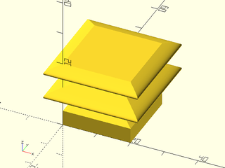
Example 9: This box is much thicker, and cut in half to show the profiles. Note also that we can turn check_valid off for the outside and for the top inside, but not for the bottom inside. This example shows use of the direct keyword syntax without the helper functions.
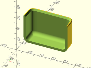
include <BOSL2/std.scad>
include <BOSL2/rounding.scad>
smallbox = square([75,50]);
roundbox = round_corners(smallbox, method="smooth", cut=4, $fn=12);
thickness=4;
height=50;
back_half(y=25, s=200)
  difference(){
    offset_sweep(roundbox, height=height, bottom=["for","offset_sweep","r",10,"type","teardrop"],
                                          top=["for","offset_sweep","r",2], steps = 22, check_valid=false);
    up(thickness)
      offset_sweep(offset(roundbox, r=-thickness, closed=true),
                    height=height-thickness, steps=22,
                    bottom=["for","offset_sweep","r",6],
                    top=["for","offset_sweep","type","chamfer","angle",30,
                         "chamfer_height",-3,"extra",1,"check_valid",false]);
}
Example 10: A box with multiple sections and rounded dividers
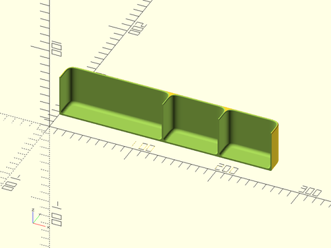
include <BOSL2/std.scad>
include <BOSL2/rounding.scad>
thickness = 2;
box = square([255,50]);
cutpoints = [0, 125, 190, 255];
rbox = round_corners(box, method="smooth", cut=4, $fn=12);
back_half(y=25, s=700)
  difference(){
    offset_sweep(rbox, height=50, check_valid=false, steps=22,
                 bottom=os_teardrop(r=2), top=os_circle(r=1));
    up(thickness)
      for(i=[0:2]){
        ofs = i==1 ? 2 : 0;
        hole = round_corners([[cutpoints[i]-ofs,0], [cutpoints[i]-ofs,50],
                              [cutpoints[i+1]+ofs, 50], [cutpoints[i+1]+ofs,0]],
                             method="smooth", cut=4, $fn=36);
        offset_sweep(offset(hole, r=-thickness, closed=true,check_valid=false),
                      height=48, steps=22, check_valid=false,
                      bottom=os_circle(r=4), top=os_circle(r=-1,extra=1));
      }
  }
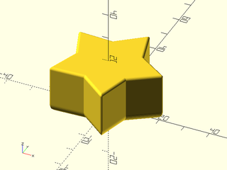
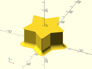
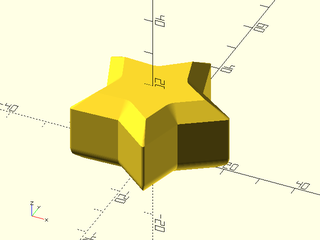
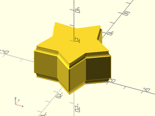
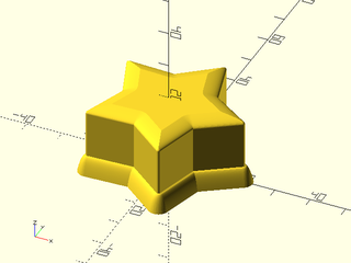
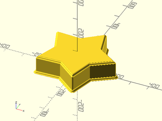
Example 11: Star shaped box
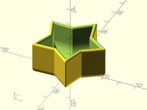
include <BOSL2/std.scad>
include <BOSL2/rounding.scad>
star = star(5, r=22, ir=13);
rounded_star = round_corners(star, cut=flatten(repeat([.5,0],5)), $fn=24);
thickness = 2;
ht=20;
difference(){
  offset_sweep(rounded_star, height=ht, bottom=["for","offset_sweep","r",4],
                                        top=["for","offset_sweep","r",1], steps=15);
  up(thickness)
      offset_sweep(offset(rounded_star,r=-thickness,closed=true),
                    height=ht-thickness, check_valid=false,
                    bottom=os_circle(r=7), top=os_circle(r=-1, extra=1),$fn=40);
  }
Example 12: A profile defined by an arbitrary sequence of points.
include <BOSL2/std.scad>
include <BOSL2/rounding.scad>
star = star(5, r=22, ir=13);
rounded_star = round_corners(star, cut=flatten(repeat([.5,0],5)), $fn=24);
profile = os_profile(points=[[0,0],[.3,.1],[.6,.3],[.9,.9], [1.2, 2.7],[.8,2.7],[.8,3]]);
offset_sweep(reverse(rounded_star), height=20, top=profile, bottom=profile, $fn=32);
Example 13: Parabolic rounding
include <BOSL2/std.scad>
include <BOSL2/rounding.scad>
star = star(5, r=22, ir=13);
rounded_star = round_corners(star, cut=flatten(repeat([.5,0],5)), $fn=24);
offset_sweep(rounded_star, height=20, top=os_profile(points=[for(r=[0:.1:2])[sqr(r),r]]),
                                       bottom=os_profile(points=[for(r=[0:.2:5])[-sqrt(r),r]]),$fn=32);
Example 14: This example uses a sine wave offset profile. Note that we give no specification for the bottom, so it is straight.
include <BOSL2/std.scad>
include <BOSL2/rounding.scad>
sq = [[0,0],[20,0],[20,20],[0,20]];
sinwave = os_profile(points=[for(theta=[0:5:720]) [4*sin(theta), theta/700*15]]);
offset_sweep(sq, height=20, top=sinwave, $fn=32);
Example 15: The same as the previous example but offset="delta"
include <BOSL2/std.scad>
include <BOSL2/rounding.scad>
sq = [[0,0],[20,0],[20,20],[0,20]];
sinwave = os_profile(points=[for(theta=[0:5:720]) [4*sin(theta), theta/700*15]]);
offset_sweep(sq, height=20, top=sinwave, offset="delta");
Example 16: a box with a flared top. A nice roundover on the top requires a profile edge, but we can use "extra" to create a small chamfer.
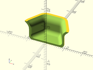
include <BOSL2/std.scad>
include <BOSL2/rounding.scad>
rhex = round_corners(hexagon(side=10), method="smooth", joint=2, $fs=0.2);
back_half()
  difference(){
    offset_sweep(rhex, height=10, bottom=os_teardrop(r=2), top=os_teardrop(r=-4, extra=0.2));
    up(1)
      offset_sweep(offset(rhex,r=-1), height=9.5, bottom=os_circle(r=2), top=os_teardrop(r=-4));
  }
Example 17: Using os_mask to create ogee profiles:
include <BOSL2/std.scad>
include <BOSL2/rounding.scad>
ogee = mask2d_ogee([
    "xstep",1,  "ystep",1,  // Starting shoulder.
    "fillet",5, "round",5,  // S-curve.
    "ystep",1,              // Ending shoulder.
]);
star = star(5, r=220, ir=130);
rounded_star = round_corners(star, cut=flatten(repeat([5,0],5)), $fn=24);
offset_sweep(rounded_star, height=100, top=os_mask(ogee), bottom=os_mask(ogee,out=true));
Synopsis: Make a solid from geometry where offset changes along the object's length. [Geom]
See Also: offset_sweep(), rounded_prism(), bent_cutout_mask(), join_prism(), linear_sweep()
Usage: Basic usage. See below for full options
- convex_offset_extrude(height, [bottom], [top], ...) 2D-CHILDREN;
Description:
Extrudes 2d children with layers formed from the convex hull of the offset of each child according to a sequence of offset values.
Like offset_sweep this module can use built-in offset profiles to provide treatments such as roundovers or chamfers but unlike offset_sweep() it
operates on 2d children rather than a point list. Each offset is computed using
the native offset() module from the input geometry.
If your shape has corners that you want rounded by offset be sure to set $fn or $fs appropriately.
If your geometry has internal holes or is too small for the specified offset then you may get
unexpected results.
The build-in profiles are: circular rounding, teardrop rounding, continuous curvature rounding, and chamfer. Also note that when a rounding radius is negative the rounding will flare outwards. The easiest way to specify the profile is by using the profile helper functions. These functions take profile parameters, as well as some general settings and translate them into a profile specification, with error checking on your input. The description below describes the helper functions and the parameters specific to each function. Below that is a description of the generic settings that you can optionally use with all of the helper functions. For more details on the "cut" and "joint" rounding parameters, and on continuous curvature rounding, see Types of Roundover.
The final shape is created by combining convex hulls of small extrusions. The thickness of these small extrusions may result
your model being slightly too long (if the curvature at the end is flaring outward), so if the exact length is very important
you may need to intersect with a bounding cube. (Note that extra length can also be intentionally added with the extra argument.)
- profile: os_profile(points) Define the offset profile with a list of points. The first point must be [0,0] and the roundover should rise in the positive y direction, with positive x values for inward motion (standard roundover) and negative x values for flaring outward. If the y value ever decreases then you might create a self-intersecting polyhedron, which is invalid. Such invalid polyhedra will create cryptic assertion errors when you render your model and it is your responsibility to avoid creating them. Note that the starting point of the profile is the center of the extrusion. If you use a profile as the top it will rise upwards. If you use it as the bottom it will be inverted, and will go downward.
- circle: os_circle(r|cut). Define circular rounding either by specifying the radius or cut distance.
- smooth: os_smooth(cut|joint, [k]). Define continuous curvature rounding, with
cutandjointas for round_corners. The k parameter controls how fast the curvature changes and should be between 0 and 1. - teardrop: os_teardrop(r|cut). Rounding using a 1/8 circle that then changes to a 45 degree chamfer. The chamfer is at the end, and enables the object to be 3d printed without support. The radius gives the radius of the circular part.
- chamfer: os_chamfer([height], [width], [cut], [angle]). Chamfer the edge at desired angle or with desired height and width. You can specify height and width together and the angle will be ignored, or specify just one of height and width and the angle is used to determine the shape. Alternatively, specify "cut" along with angle to specify the cut back distance of the chamfer.
The general settings that you can use with all of the helper functions are mostly used to control how offset_sweep() calls the offset() function.
- extra: Add an extra vertical step of the specified height, to be used for intersections or differences. This extra step will extend the resulting object beyond the height you specify. Default: 0
- steps: Number of vertical steps to use for the profile. (Not used by os_profile). Default: 16
- offset: Select "round" (r=), "delta" (delta=), or "chamfer" offset types for offset. Default: "round"
Many of the arguments are described as setting "default" values because they establish settings which may be overridden by the top and bottom profile specifications.
You will generally want to use the above helper functions to generate the profiles. The profile specification is a list of pairs of keywords and values, e.g. ["r",12, type, "circle"]. The keywords are
- "type" - type of rounding to apply, one of "circle", "teardrop", "chamfer", "smooth", or "profile" (Default: "circle")
- "r" - the radius of the roundover, which may be zero for no roundover, or negative to round or flare outward. Default: 0
- "cut" - the cut distance for the roundover or chamfer, which may be negative for flares
- "chamfer_width" - the width of a chamfer
- "chamfer_height" - the height of a chamfer
- "angle" - the chamfer angle, measured from the vertical (so zero is vertical, 90 is horizontal). Default: 45
- "joint" - the joint distance for a "smooth" roundover
- "k" - the curvature smoothness parameter for "smooth" roundovers, a value in [0,1]. Default: 0.75
- "points" - point list for use with the "profile" type
- "extra" - extra height added for unions/differences. This makes the shape taller than the requested height. (Default: 0)
- "steps" - number of vertical steps to use for the roundover. Default: 16.
- "offset" - select "round" (r=) or "delta" (delta=) offset type for offset. Default: "round"
Note that unlike offset_sweep, because the offset operation is always performed from the base shape, using chamfered offsets does not increase the
number of vertices or lead to any special complications.
Arguments:
| By Position | What it does |
|---|---|
height / length / l / h
|
total height (including rounded portions, but not extra sections) of the output. Default: combined height of top and bottom end treatments. |
bottom |
rounding spec for the bottom end |
top |
rounding spec for the top end. |
| By Name | What it does |
|---|---|
offset |
default offset, "round", "delta", or "chamfer". Default: "round"
|
steps |
default step count. Default: 16 |
extra |
default extra height. Default: 0 |
cut |
default cut value. |
chamfer_width |
default width value for chamfers. |
chamfer_height |
default height value for chamfers. |
angle |
default angle for chamfers. Default: 45 |
joint |
default joint value for smooth roundover. |
k |
default curvature parameter value for "smooth" roundover |
convexity |
convexity setting for use with polyhedron. Default: 10 |
Example 1: Chamfered elliptical prism. If you stretch a chamfered cylinder the chamfer will be uneven.
include <BOSL2/std.scad>
include <BOSL2/rounding.scad>
convex_offset_extrude(bottom = os_chamfer(height=-2),
                      top=os_chamfer(height=1), height=7)
  xscale(4)circle(r=6,$fn=64);
Example 2: Elliptical prism with circular roundovers.
include <BOSL2/std.scad>
include <BOSL2/rounding.scad>
convex_offset_extrude(bottom=os_circle(r=-2),
                      top=os_circle(r=1), height=7,steps=10)
  xscale(4)circle(r=6,$fn=64);
Example 3: If you give a non-convex input you get a convex hull output
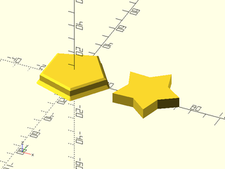
include <BOSL2/std.scad>
include <BOSL2/rounding.scad>
right(50) linear_extrude(height=7) star(5,r=22,ir=13);
convex_offset_extrude(bottom = os_chamfer(height=-2),
                      top=os_chamfer(height=1), height=7, $fn=32)
  star(5,r=22,ir=13);
Synopsis: Make a rounded 3d object by connecting two polygons with the same vertex count. [Geom] [VNF]
See Also: offset_sweep(), convex_offset_extrude(), bent_cutout_mask(), join_prism()
Usage: as a module
- rounded_prism(bottom, [top], [height=|h=|length=|l=], [joint_top=], [joint_bot=], [joint_sides=], [k=], [k_top=], [k_bot=], [k_sides=], [splinesteps=], [debug=], [convexity=],...) [ATTACHMENTS];
Usage: as a function
- vnf = rounded_prism(bottom, [top], [height=|h=|length=|l=], [joint_top=], [joint_bot=], [joint_sides=], [k=], [k_top=], [k_bot=], [k_sides=], [splinesteps=], [debug=]);
Description:
Construct a generalized prism with continuous curvature rounding. You supply the polygons for the top and bottom of the prism. The only limitation is that joining the edges must produce a valid polyhedron with coplanar side faces. You specify the rounding by giving the joint distance away from the corner for the rounding curve. The k parameter ranges from 0 to 1 with a default of 0.5. Larger values give a more abrupt transition and smaller ones a more gradual transition. If you set the value much higher than 0.8 the curvature changes abruptly enough that though it is theoretically continuous, it may not be continuous in practice. A value of 0.92 is a good approximation to a circle. If you set it very small then the transition is so gradual that the roundover may be very small. If you want a very smooth roundover, set the joint parameter as large as possible and then adjust the k value down as low as gives a sufficiently large roundover. See Types of Roundover for more information on continuous curvature rounding.
You can specify the bottom and top polygons by giving two compatible 3d paths. You can also give 2d paths and a height/length and the two shapes will be offset in the z direction from each other. The final option is to specify just the bottom along with a height/length; in this case the top will be a copy of the bottom, offset in the z direction by the specified height.
You define rounding for all of the top edges, all of the bottom edges, and independently for each of the connecting side edges. You specify rounding the rounding by giving the joint distance for where the curved section should start. If the joint distance is 1 then it means the curved section begins 1 unit away from the edge (in the perpendicular direction). Typically each joint distance is a scalar value and the rounding is symmetric around each edge. However, you can specify a 2-vector for the joint distance to produce asymmetric rounding which is different on the two sides of the edge. This may be useful when one one edge in your polygon is much larger than another. For the top and bottom you can specify negative joint distances. If you give a scalar negative value then the roundover will flare outward. If you give a vector value then a negative value then if joint_top[0] is negative the shape will flare outward, but if joint_top[1] is negative the shape will flare upward. At least one value must be non-negative. The same rules apply for joint_bot. The joint_sides parameter must be entirely nonnegative.
If the roundings at two adjacent side edges exceed the width of the face then the polyhedron will have self-intersecting faces, so it will be invalid.
Similarly, if the roundings on the top or bottom edges cross the top face and intersect with each other, the resulting polyhedron is invalid:
the top face after the roundings are applied must be a valid, non-degenerate polyhedron. There are two exceptions: it is permissible to
construct a top that is a single point or two points. This means you can completely round a cube by setting the joint to half of
the cube's width.
If you set debug to true the module version will display the polyhedron even when it is invalid and it will show the bezier patches at the corners.
This can help troubleshoot problems with your parameters. With the function form setting debug to true causes it to return [patches,vnf] where
patches is a list of the bezier control points for the corner patches.
Note that rounded_prism() is not well suited to rounding shapes that have already been rounded, or that have many points. It works best when the top and bottom are polygons with well-defined corners. When the polygons have been rounded already, further rounding generates tiny bezier patches patches that can more easily interfere, giving rise to an invalid polyhedron. It's also slow because you get bezier patches for every corner in the model.
Arguments:
| By Position | What it does |
|---|---|
bottom |
2d or 3d path describing bottom polygon |
top |
2d or 3d path describing top polygon (must be the same dimension as bottom) |
| By Name | What it does |
|---|---|
height / length / h / l
|
height of the shape when you give 2d bottom |
joint_top |
rounding length for top (number or 2-vector). Default: 0 |
joint_bot |
rounding length for bottom (number or 2-vector). Default: 0 |
joint_sides |
rounding length for side edges, a number/2-vector or list of them. Default: 0 |
k |
continuous curvature rounding parameter for all edges. Default: 0.5 |
k_top |
continuous curvature rounding parameter for top |
k_bot |
continuous curvature rounding parameter for bottom |
k_sides |
continuous curvature rounding parameter side edges, a number or vector. |
splinesteps |
number of segments to use for curved patches. Default: 16 |
debug |
turn on debug mode which displays illegal polyhedra and shows the bezier corner patches for troubleshooting purposes. Default: False |
convexity |
convexity parameter for polyhedron(), only for module version. Default: 10 |
anchor |
Translate so anchor point is at the origin. (module only) Default: "origin" |
spin |
Rotate this many degrees around Z axis after anchor. (module only) Default: 0 |
orient |
Vector to rotate top towards after spin (module only) |
atype |
Select "hull" or "intersect" anchor types. (module only) Default: "hull" |
cp |
Centerpoint for determining "intersect" anchors or centering the shape. Determintes the base of the anchor vector. Can be "centroid", "mean", "box" or a 3D point. (module only) Default: "centroid" |
Example 1: Uniformly rounded pentagonal prism
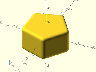
include <BOSL2/std.scad>
include <BOSL2/rounding.scad>
rounded_prism(pentagon(3), height=3,
              joint_top=0.5, joint_bot=0.5, joint_sides=0.5);
Example 2: Maximum possible rounding.
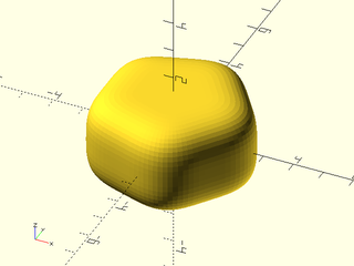
include <BOSL2/std.scad>
include <BOSL2/rounding.scad>
rounded_prism(pentagon(3), height=3,
              joint_top=1.5, joint_bot=1.5, joint_sides=1.5);
Example 3: Decreasing k from the default of 0.5 to 0.3 gives a smoother round over which takes up more space, so it appears less rounded.
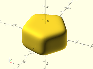
include <BOSL2/std.scad>
include <BOSL2/rounding.scad>
rounded_prism(pentagon(3), height=3, joint_top=1.5, joint_bot=1.5,
              joint_sides=1.5, k=0.3, splinesteps=32);
Example 4: Increasing k from the default of 0.5 to 0.92 approximates a circular roundover, which does not have continuous curvature. Notice the visible "edges" at the boundary of the corner and edge patches.

include <BOSL2/std.scad>
include <BOSL2/rounding.scad>
rounded_prism(pentagon(3), height=3, joint_top=0.5,
              joint_bot=0.5, joint_sides=0.5, k=0.92);
Example 5: rounding just one edge
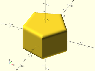
include <BOSL2/std.scad>
include <BOSL2/rounding.scad>
rounded_prism(pentagon(side=3), height=3, joint_top=0.5, joint_bot=0.5,
              joint_sides=[0,0,0.5,0,0], splinesteps=16);
Example 6: rounding all the edges differently
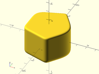
include <BOSL2/std.scad>
include <BOSL2/rounding.scad>
rounded_prism(pentagon(side=3), height=3, joint_top=0.25, joint_bot=0.5,
              joint_sides=[1.7,.5,.7,1.2,.4], splinesteps=32);
Example 7: different k values for top, bottom and sides
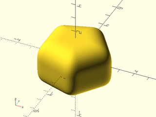
include <BOSL2/std.scad>
include <BOSL2/rounding.scad>
rounded_prism(pentagon(side=3.0), height=3.0, joint_top=1.4, joint_bot=1.4,
              joint_sides=0.7, k_top=0.7, k_bot=0.3, k_sides=0.5, splinesteps=48);
Example 8: flared bottom
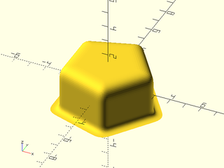
include <BOSL2/std.scad>
include <BOSL2/rounding.scad>
rounded_prism(pentagon(3), height=3, joint_top=1.0,
              joint_bot=-0.5, joint_sides=0.5);
Example 9: truncated pyramid
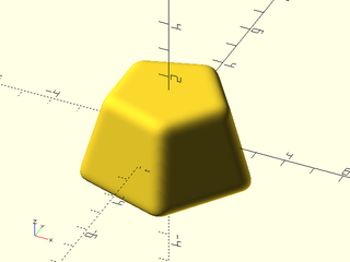
include <BOSL2/std.scad>
include <BOSL2/rounding.scad>
rounded_prism(pentagon(3), apply(scale(.7),pentagon(3)),
              height=3, joint_top=0.5, joint_bot=0.5, joint_sides=0.5);
Example 10: top translated
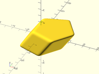
include <BOSL2/std.scad>
include <BOSL2/rounding.scad>
rounded_prism(pentagon(3), apply(right(2),pentagon(3)),
              height=3, joint_top=0.5, joint_bot=0.5, joint_sides=0.5);
Example 11: top rotated: fails due to non-coplanar side faces
include <BOSL2/std.scad>
include <BOSL2/rounding.scad>
rounded_prism(pentagon(3), apply(rot(45),pentagon(3)), height=3,
              joint_top=0.5, joint_bot=0.5, joint_sides=0.5);
Example 12: skew top
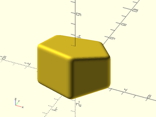
include <BOSL2/std.scad>
include <BOSL2/rounding.scad>
rounded_prism(path3d(pentagon(3)), apply(affine3d_skew_yz(0,-20),path3d(pentagon(3),3)),
              joint_top=0.5, joint_bot=0.5, joint_sides=0.5);
Example 13: this rotation gives coplanar sides
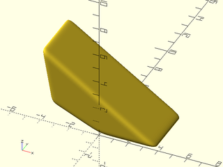
include <BOSL2/std.scad>
include <BOSL2/rounding.scad>
rounded_prism(path3d(square(4)), apply(yrot(-100)*right(2),path3d(square(4),3)),
              joint_top=0.5, joint_bot=0.5, joint_sides=0.5);
Example 14: a shape with concave corners
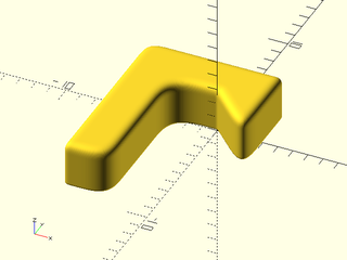
include <BOSL2/std.scad>
include <BOSL2/rounding.scad>
M = path3d(turtle(["left", 180, "length",3,"move", "left", "move", 3, "right",
                   "move", "right", "move", 4, "right", "move", 3, "right", "move", 2]));
rounded_prism(M, apply(up(3),M), joint_top=0.75, joint_bot=0.2,
              joint_sides=[.2,2.5,2,0.5,1.5,.5,2.5], splinesteps=32);
Example 15: using debug mode to see the corner patch sizes, which may help figure out problems with interfering corners or invalid polyhedra. The corner patches must not intersect each other.

include <BOSL2/std.scad>
include <BOSL2/rounding.scad>
M = path3d(turtle(["left", 180, "length",3,"move", "left", "move", 3, "right",
                   "move", "right", "move", 4, "right", "move", 3, "right", "move", 2]));
rounded_prism(M, apply(up(3),M), joint_top=0.75, joint_bot=0.2,
              joint_sides=[.2,2.5,2,0.5,1.5,.5,2.5], splinesteps=16,debug=true);
Example 16: applying transformation to the previous example
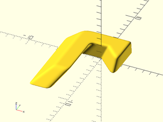
include <BOSL2/std.scad>
include <BOSL2/rounding.scad>
M = path3d(turtle(["left", 180, "length",3,"move", "left", "move", 3, "right",
                   "move", "right", "move", 4, "right", "move", 3, "right", "move", 2]));
rounded_prism(M, apply(right(1)*scale(.75)*up(3),M), joint_top=0.5, joint_bot=0.2,
              joint_sides=[.2,1,1,0.5,1.5,.5,2], splinesteps=32);
Example 17: this example shows most of the different types of patches that rounded_prism creates. Note that some of the patches are close to interfering with each other across the top of the polyhedron, which would create an invalid result.
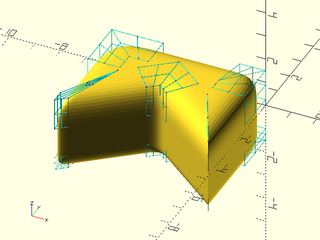
include <BOSL2/std.scad>
include <BOSL2/rounding.scad>
N = apply(rot(180)*yscale(.8),turtle(["length",3,"left", "move", 2, "right", 135,"move", sqrt(2),
                                      "left", "move", sqrt(2), "right", 135, "move", 2]));
rounded_prism(N, height=3, joint_bot=0.5, joint_top=1.25, joint_sides=[[1,1.75],0,.5,.5,2], debug=true);
Example 18: This object has different scales on its different axies. Here is the largest symmetric rounding that fits. Note that the rounding is slightly smaller than the object dimensions because of roundoff error.
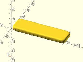
include <BOSL2/std.scad>
include <BOSL2/rounding.scad>
rounded_prism(square([100.1,30.1]), height=8.1, joint_top=4, joint_bot=4,
              joint_sides=15, k_sides=0.3, splinesteps=32);
Example 19: Using asymetric rounding enables a much more rounded form:
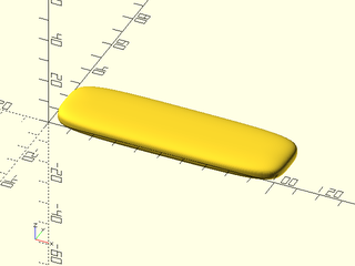
include <BOSL2/std.scad>
include <BOSL2/rounding.scad>
rounded_prism(square([100.1,30.1]), height=8.1, joint_top=[15,4], joint_bot=[15,4],
              joint_sides=[[15,50],[50,15],[15,50],[50,15]], k_sides=0.3, splinesteps=32);
Example 20: Flaring the top upward instead of outward. The bottom has an asymmetric rounding with a small flare but a large rounding up the side.
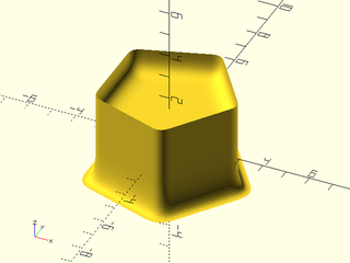
include <BOSL2/std.scad>
include <BOSL2/rounding.scad>
rounded_prism(pentagon(3), height=3, joint_top=[1,-1],
              joint_bot=[-0.5,2], joint_sides=0.5);
Example 21: Sideways polygons:
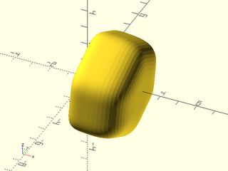
include <BOSL2/std.scad>
include <BOSL2/rounding.scad>
rounded_prism(apply(yrot(95),path3d(hexagon(3))), apply(yrot(95), path3d(hexagon(3),3)),
              joint_top=2, joint_bot=1, joint_sides=1);
Example 22: Chamfer a polyhedron by setting splinesteps to 1
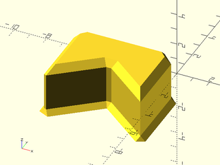
include <BOSL2/std.scad>
include <BOSL2/rounding.scad>
N = apply(rot(180)*yscale(.8),turtle(["length",3,"left", "move", 2, "right", 135,"move", sqrt(2),
                                      "left", "move", sqrt(2), "right", 135, "move", 2]));
rounded_prism(N, height=3, joint_bot=-0.3, joint_top=.4, joint_sides=[.75,0,.2,.2,.7], splinesteps=1);
Synopsis: Create a mask for making a round-edged cutout in a cylindrical shell. [Geom]
See Also: offset_sweep(), convex_offset_extrude(), rounded_prism(), join_prism()
Usage:
- bent_cutout_mask(r|radius, thickness, path);
Description:
Creates a mask for cutting a round-edged hole out of a vertical cylindrical shell. The specified radius is the center radius of the cylindrical shell. The path needs to be sampled finely enough so that it can follow the curve of the cylinder. The thickness may need to be slighly oversized to handle the faceting of the cylinder. The path is wrapped around a cylinder, keeping the same dimensions that is has on the plane, with y axis mapping to the z axis and the x axis bending around the curve of the cylinder. The angular span of the path on the cylinder must be somewhat less than 180 degrees, and the path shouldn't have closely spaced points at concave points of high curvature because this will cause self-intersection in the mask polyhedron, resulting in CGAL failures.
Arguments:
| By Position | What it does |
|---|---|
r / radius
|
center radius of the cylindrical shell to cut a hole in |
thickness |
thickness of cylindrical shell (may need to be slighly oversized) |
path |
2d path that defines the hole to cut |
Example 1: The mask as long pointed ends because this was the most efficient way to close off those ends.
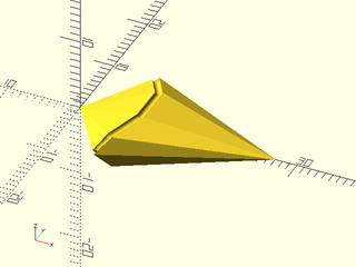
include <BOSL2/std.scad>
include <BOSL2/rounding.scad>
bent_cutout_mask(10, 1, apply(xscale(3),circle(r=3)),$fn=64);
Example 2: An elliptical hole. Note the thickness is slightly increased to 1.05 compared to the actual thickness of 1.
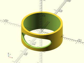
include <BOSL2/std.scad>
include <BOSL2/rounding.scad>
rot(-90) {
  $fn=128;
  difference(){
    cyl(r=10.5, h=10);
    cyl(r=9.5, h=11);
    bent_cutout_mask(10, 1.05, apply(xscale(3),circle(r=3)),
                     $fn=64);
  }
}
Example 3: An elliptical hole in a thick cylinder
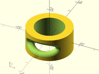
include <BOSL2/std.scad>
include <BOSL2/rounding.scad>
rot(-90) {
  $fn=128;
  difference(){
    cyl(r=14.5, h=15);
    cyl(r=9.5, h=16);
    bent_cutout_mask(12, 5.1, apply(xscale(3),circle(r=3)));
  }
}
Example 4: Complex shape example
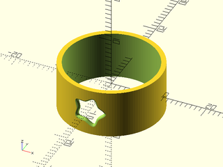
include <BOSL2/std.scad>
include <BOSL2/rounding.scad>
rot(-90) {
  $fn=128;
  difference(){
    cyl(r=10.5, h=10, $fn=128);
    cyl(r=9.5, h=11, $fn=128);
    bent_cutout_mask(10, 1.05,
      apply(scale(3),
        supershape(step=2,m1=5, n1=0.3,n2=1.7)),$fn=32);
  }
}
Example 5: this shape is invalid due to self-intersections at the inner corners
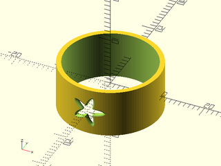
include <BOSL2/std.scad>
include <BOSL2/rounding.scad>
rot(-90) {
  $fn=128;
  difference(){
    cylinder(r=10.5, h=10,center=true);
    cylinder(r=9.5, h=11,center=true);
    bent_cutout_mask(10, 1.05,
      apply(scale(3),
        supershape(step=2,m1=5, n1=0.1,n2=1.7)),$fn=32);
  }
}
Example 6: increasing the step gives a valid shape, but the shape looks terrible with so few points.
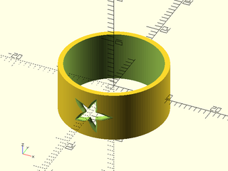
include <BOSL2/std.scad>
include <BOSL2/rounding.scad>
rot(-90) {
  $fn=128;
  difference(){
    cylinder(r=10.5, h=10,center=true);
    cylinder(r=9.5, h=11,center=true);
    bent_cutout_mask(10, 1.05,
      apply(scale(3),
        supershape(step=12,m1=5, n1=0.1,n2=1.7)),$fn=32);
  }
}
Example 7: uniform resampling produces a somewhat better result, but room remains for improvement. The lesson is that concave corners in your cutout cause trouble. To get a very good result we need to non-uniformly sample the supershape with more points at the star tips and few points at the inner corners.

include <BOSL2/std.scad>
include <BOSL2/rounding.scad>
rot(-90) {
  $fn=128;
  difference(){
    cylinder(r=10.5, h=10,center=true);
    cylinder(r=9.5, h=11,center=true);
    bent_cutout_mask(10, 1.05,
      apply(scale(3), resample_path(
           supershape(step=1,m1=5, n1=0.10,n2=1.7),
           60,closed=true)),
      $fn=32);
  }
}
Example 8: The cutout spans 177 degrees. If you decrease the tube radius to 2.5 the cutout spans over 180 degrees and the model fails.
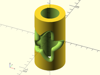
include <BOSL2/std.scad>
include <BOSL2/rounding.scad>
r=2.6;     // Don't make this much smaller or it will fail
rot(-90) {
  $fn=128;
  difference(){
    tube(or=r, wall=1, h=10, anchor=CENTER);
    bent_cutout_mask(r-0.5, 1.05,
      apply(scale(3),
        supershape(step=1,m1=5, n1=0.15,n2=1.7)),$fn=32);
  }
}
Example 9: A square hole is not as simple as it seems. The model valid, but wrong, because the square didn't have enough samples to follow the curvature of the cylinder.
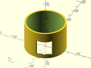
include <BOSL2/std.scad>
include <BOSL2/rounding.scad>
r=25;
rot(-90) {
  $fn=128;
  difference(){
    tube(or=r, wall=2, h=35, anchor=BOT);
    bent_cutout_mask(r-1, 2.1, back(5,p=square([18,18])));
  }
}
Example 10: Adding additional points fixed this problem
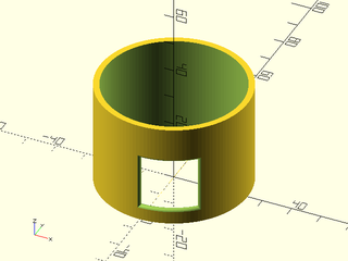
include <BOSL2/std.scad>
include <BOSL2/rounding.scad>
r=25;
rot(-90) {
  $fn=128;
  difference(){
    tube(or=r, wall=2, h=35, anchor=BOT);
    bent_cutout_mask(r-1, 2.1,
      subdivide_path(back(5,p=square([18,18])),64,closed=true));
  }
}
Example 11: Rounding just the exterior corners of this star avoids the problems we had above with concave corners of the supershape, as long as we don't oversample the star.
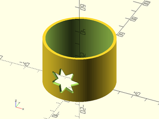
include <BOSL2/std.scad>
include <BOSL2/rounding.scad>
r=25;
rot(-90) {
  $fn=128;
  difference(){
    tube(or=r, wall=2, h=35, anchor=BOT);
    bent_cutout_mask(r-1, 2.1,
      apply(back(15),
        subdivide_path(
          round_corners(star(n=7,ir=5,or=10),
                        cut=flatten(repeat([0.5,0],7)),$fn=32),
          14*15,closed=true)));
  }
}
Example 12: Cutting a slot in a cylinder is tricky if you want rounded corners at the top. This slot profile has slightly angled top edges to blend into the top edge of the cylinder.
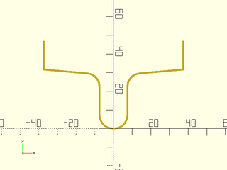
include <BOSL2/std.scad>
include <BOSL2/rounding.scad>
function slot(slotwidth, slotheight, slotradius) = let(
    angle = 85,
    slot = round_corners(
        turtle([
            "right",
            "move", slotwidth,
            "left", angle,
            "move", 2*slotwidth,
            "right", angle,
            "move", slotheight,
            "left",
            "move", slotwidth,
            "left",
            "move", slotheight,
            "right", angle,
            "move", 2*slotwidth,
            "left", angle,
            "move", slotwidth
        ]),
        radius = [0,0,each repeat(slotradius,4),0,0], closed=false
    )
) apply(left(max(column(slot,0))/2)*fwd(min(column(slot,1))), slot);
stroke(slot(15,29,7));
Example 13: A cylindrical container with rounded edges and a rounded finger slot.
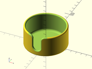
include <BOSL2/std.scad>
include <BOSL2/rounding.scad>
function slot(slotwidth, slotheight, slotradius) = let(
    angle = 85,
    slot = round_corners(
        turtle([
            "right",
            "move", slotwidth,
            "left", angle,
            "move", 2*slotwidth,
            "right", angle,
            "move", slotheight,
            "left",
            "move", slotwidth,
            "left",
            "move", slotheight,
            "right", angle,
            "move", 2*slotwidth,
            "left", angle,
            "move", slotwidth
        ]),
        radius = [0,0,each repeat(slotradius,4),0,0], closed=false
    )
) apply(left(max(column(slot,0))/2)*fwd(min(column(slot,1))), slot);
diam = 80;
wall = 4;
height = 40;
rot(-90) {
    $fn=128;
    difference(){
        cyl(d=diam, rounding=wall/2, h=height, anchor=BOTTOM);
        up(wall)cyl(d=diam-2*wall, rounding1=wall, rounding2=-wall/2, h=height-wall+.01, anchor=BOTTOM);
        bent_cutout_mask(diam/2-wall/2, wall+.1, subdivide_path(apply(back(10),slot(15, 29, 7)),250));
    }
}
Synopsis: Join an arbitrary prism to a plane, sphere, cylinder or another arbitrary prism with a fillet. [Geom] [VNF]
See Also: offset_sweep(), convex_offset_extrude(), rounded_prism(), bent_cutout_mask()
Usage: The two main forms with most common options
- join_prism(polygon, base, length=|height=|l=|h=, fillet=, [base_T=], [scale=], [prism_end_T=], [short=], ...) [ATTACHMENTS];
- join_prism(polygon, base, aux=, fillet=, [base_T=], [aux_T=], [scale=], [prism_end_T=], [short=], ...) [ATTACHMENTS];
Usage: As function
- vnf = join_prism( ... );
Description:
This function creates a smooth fillet between one or both ends of an arbitrary prism and various other shapes: a plane, a sphere, a cylinder,
or another arbitrary prism. The fillet is a continuous curvature rounding with a specified width/height. This module is very general
and hence has a complex interface. The examples below form a tutorial on how to use join_prism that steps
through the various options and how they affect the results. Be sure to check the examples for help understanding how the various options work.
When joining between planes this function produces similar results to rounded_prism(). This function works best when the prism
cross section is a continuous shape with a high sampling rate and without sharp corners. If you have sharp corners you should consider
giving them a small rounding first. When the prism cross section has concavities the fillet size will be limited by the curvature of those concavities.
In contrast, rounded_prism() works best on a prism that has fewer points. A high sampling rate can lead to problems, and rounding
over sharp corners leads to poor results.
You specify the prism by giving its cross section as a 2D path. The cross section will always be the orthogonal cross section of the prism. Depending on end conditions, the ends may not be perpendicular to the axis of the prism, but the cross section you give is always perpendicular to that cross section.
Figure 1: The layout and terminology used by join_prism. The "base object" is centered on the origin. The "auxiliary object" (if present) is some distance away so there is room for the "joiner prism" to connect the two objects. The blue line is the axis of the jointer prism. It will be at the origin of the shape you supply for defining that prism. The "root" point of the joiner prism is the point where the prism axis intersects the base. The prism end point is where the prism axis intersects the auxiliary object. If you don't give an auxiliary object then the prism end point is distance length along the axis from the root.

You must include a base ("plane", "sphere", "cylinder", "cyl"), or a polygon describing the cross section of a base prism. If you specify a
sphere or cylinder you must give base_r or base_d to specify the radius or diameter of the base object. If you choose a cylinder or a polygonal
prism then the base object appears aligned with the X axis. In the case of the planar base, the
joining prism will have one end of its axis at the origin. As shown above, the point where the joining prism attaches to its base is the "root" of the prism.
If you use some other base shape, the root will be adjusted so that it is on the boundary of your shape. This happens by finding the intersection
of the joiner prisms's axis and using that as the root. By default the prism axis is parallel to the Z axis.
You may give base_T, a rotation operator that will be applied to the base. This is
useful to tilt a planar or cylindrical base. The base_T operator must be an origin-centered rotation like yrot(25).
You may optionally specify an auxiliary shape. When you do this, the joining prism connects the base to the auxiliary shape,
which must be one of "none", "plane", "sphere", "cyl", or "cylinder". You can also set it to a polygon to create an arbitrary
prism for the auxiliary shape. As is the case for the base, auxiliary cylinders and prisms appear oriented along the X axis.
For a cylinder or sphere you must use aux_r or aux_d to specify the radius or diameter.
The auxiliary shape appears centered on the origin and will most likely be invalid as an end location unless you translate it to a position
away from the base object. The aux_T operator operates on the auxiliary object, and unlike base_T can be a rotation that includes translation
operations (or is a non-centered rotation).
When you specify an auxiliary object, the joiner prism axis is initially the line connecting the origin (the base center point) to the auxiliary
object center point. The joiner prism end point is determined analogously to how the root is determined, by intersecting the joiner
prism axis with the auxiliary object. Note that this means that if aux_T is a rotation it will change the joiner prism root, because
the rotated prism axis will intersect the base in a different location. If you do not give an auxiliary object then you must give
the length/height parameter to specify the prism length. This gives the length of the prism measured from the root to the end point.
Note that the joint with a curved base may significantly extend the length of the joiner prism: it's total length will often be larger than
the length you request.
For the cylinder and spherical objects you may with to joint a prism to the concave surface. You can do this by setting a negative
radius for the base or auxiliary object. When base_r is negative, and the joiner prism axis is vertical, the prism root will be below the
XY plane. In this case it is actually possible to use the same object for base and aux and you can get a joiner prism that crosses a cylindrical
or spherical hole.
When placing prisms inside a hole, an ambiguity can arise about how to identify the root and end of the joiner prism. The prism axis will have
two intersections with a cylinder and both are potentially valid roots. When the auxiliary object is entirely inside the hole, or the auxiliary
object is a sphere or cylinder with negative radius that intersections the base, both prism directions produce a valid
joiner prism that meets the hole's concave surface, so two valid interpretations exist. By default, the longer prism will be returned.
You can select the shorter prism by setting short=true. If you specify short=true when the base has a negative radius, but only one valid
prism exists, you'll get an error, but it won't clearly identify that a bogus short=true was the real cause.
You can also alter your prism by using the prism_end_T operator which applies to the end point of the prism. It does not effect
the root of the prism. The prism_end_T operator is applied in a coordinate system where the root of the
prism is the origin, so if you set it to a rotation the prism base will stay rooted at the same location and the prism will rotate
in the specified fashion. After prism_end_T is applied, the prism axis will probably be different and the resulting new end point will
probably not be on the auxiliary object, or it will have changed the length of the prism. Therefore, the end point is recalculated
to achieve the specified length (if aux is "none") or to contact the auxiliary object, if you have specified one. This means, for example,
that setting prism_end_T to a scale operation won't change the result because it doesn't alter the prism axis.
The size of the fillets is determined by the fillet, fillet_base, and fillet_aux parameters. The fillet parameter will control both
ends of the prism, or you can set the ends independently. The fillets must be nonnegative except when the prism joints a plane.
In this case a negative fillet gives a roundover. In the case of no auxiliary object you can use round_end to round over the planar
far end of the joiner prism. By default, the fillet is constructed using a method that produces a fillet with a uniform height along
the joiner prism. This can be limiting when connectijng to objects with high curvature, so you can turn it off using the uniform option.
See the figures below for an explanation of the uniform and non-uniform filleting methods.
The overlap is a potentially tricky parameter. It specifies how much extra material to create underneath the filleted prism so it overlaps the object that it joins to, ensuring valid unions. For joins to convex objects you can choose a small value, but when joining to a concave object the overlap may need to be very large to ensure that the base of the joiner prism is well-behaved. In such cases you may need to use an intersection remove excess base.
Figure 2: Uniform fillet method. This image shows how the fillet we construct a uniform fillet. The pictures shows the cross section that is perpendicular to the prism. The blue curve represents the base object surface. The vertical line is the side of the prism. To construct a fillet we travel along the surface of the base, following the curve, until we have moved the fillet length, a. This defines the point u. We then construct a tangent line to the base and find its intersection, v, with the prism. Note that if the base is steeply curved, this tangent may fail to intersect, and the algorithm will fail with an error because v does not exist. Finally we locate w to be distance a above the point where the prism intersects the base object. The fillet is defined by the [u,v,w] triple and is shown in red. Note that with this method, the fillet is always height a above the base, so it makes a uniform curve parallel to the base object. However, when the base curvature is more extreme, point v may end up above point w, resulting in an invalid configuration. It also happens that point v, while below w, is very close to w, so the resulting fillet has an abrupt angle near w instead of a smooth transition.

Figure 3: Non-Uniform fillet method. This method differs because point w is found by moving the fillet distance a starting at the intersection point v instead of at the base surface. This means that the [u,v,w] triple is always in the correct order to produce a valid fillet. However, the height of the fillet above the surface will vary. When the base concave, point v is below the surface of the base, which in more extreme cases can produce a fillet that goes below the base surface. The uniform method is less likely to produce this kind of result. When the base surface is a plane, the uniform and non-uniform methods are identical.

Arguments:
| By Position | What it does |
|---|---|
polygon |
polygon giving prism cross section |
base |
string specifying base object to join to ("plane","cyl","cylinder", "sphere") or a point list to use an arbitrary prism as the base. |
| By Name | What it does |
|---|---|
length / height / l / h
|
length/height of prism if aux=="none" |
scale |
scale factor for prism far end. Default: 1 |
prism_end_T |
root-centered arbitrary transform to apply to the prism's far point. Default: IDENT |
short |
flip prism direction for concave sphere or cylinder base, when there are two valid prisms. Default: false |
base_T |
origin-centered rotation operator to apply to the base |
base_r / base_d
|
base radius or diameter if you picked sphere or cylinder |
aux |
string specifying auxilary object to connect to ("none", "plane", "cyl", "cylinder", or "sphere") or a point list to use an arbitrary prism. Default: "none" |
aux_T |
rotation operator that may include translation when aux is not "none" to apply to aux |
aux_r / aux_d
|
radius or diameter of auxiliary object if you picked sphere or cylinder |
n |
number of segments in the fillet at both ends. Default: 15 |
base_n |
number of segments to use in fillet at the base |
aux_n |
number of segments to use in fillet at the aux object |
end_n |
number of segments to use in roundover at the end of prism with no aux object |
fillet |
fillet for both ends of the prism (if applicable) Must be nonnegative except for joiner prisms with planar ends |
base_fillet |
fillet for base end of prism |
aux_fillet |
fillet for joint with aux object |
end_round |
roundover of end of prism with no aux object |
overlap |
amount of overlap of prism fillet into objects at both ends. Default: 1 for normal fillets, 0 for negative fillets and roundovers |
base_overlap |
amount of overlap of prism fillet into the base object |
aux_overlap |
amount of overlap of the prism fillet into aux object |
k |
fillet curvature parameter for both ends of prism |
base_k |
fillet curvature parameter for base end of prism |
end_k / aux_k
|
fillet curvature parameter for end of prism where the aux object is |
uniform |
set to false to get non-uniform filleting at both ends (see Figures 2-3). Default: true |
base_uniform |
set to false to get non-uniform filleting at the base |
aux_uniform |
set to false to get non-uniform filleting at the auxiliary object |
debug |
set to true to allow return of various cases where self-intersection was detected |
anchor |
Translate so anchor point is at the origin. (module only) Default: "origin" |
spin |
Rotate this many degrees around Z axis after anchor. (module only) Default: 0 |
orient |
Vector to rotate top towards after spin (module only) |
atype |
Select "hull" or "intersect" anchor types. (module only) Default: "hull" |
cp |
Centerpoint for determining "intersect" anchors or centering the shape. Determintes the base of the anchor vector. Can be "centroid", "mean", "box" or a 3D point. (module only) Default: "centroid" |
Extra Anchors:
| Anchor Name | Position |
|---|---|
| "root" | Root point of the joiner prism, pointing out in the direction of the prism axis |
| "end" | End point of the joiner prism, pointing out in the direction of the prism axis |
Example 1: Here is the simplest case, a circular prism with a specified length standing vertically on a plane.
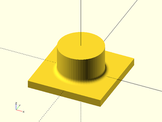
include <BOSL2/std.scad>
include <BOSL2/rounding.scad>
join_prism(circle(r=15,$fn=60),base="plane",
           length=18, fillet=3, n=12);
cube([50,50,5],anchor=TOP);
Example 2: Here we substitute an abitrary prism.
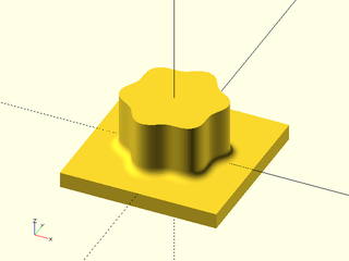
include <BOSL2/std.scad>
include <BOSL2/rounding.scad>
flower = [for(theta=lerpn(0,360,180,endpoint=false))
          (15+1.3*sin(6*theta))*[cos(theta),sin(theta)]];
join_prism(flower,base="plane",length=18, fillet=3, n=12);
cube([50,50,5],anchor=TOP);
Example 3: Here we apply a rotation of the prism, using prism_end_T, which rotates around the prism root. Note that aux_T will rotate around the origin, which is the same when the prism is joined to a plane.
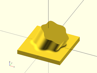
include <BOSL2/std.scad>
include <BOSL2/rounding.scad>
flower = [for(theta=lerpn(0,360,180,endpoint=false))
          (15+1.3*sin(6*theta))*[cos(theta),sin(theta)]];
join_prism(flower,base="plane",length=18, fillet=3,
           n=12, prism_end_T=yrot(25));
cube([50,50,5],anchor=TOP);
Example 4: We can use end_round to get a roundover
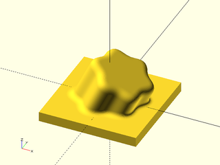
include <BOSL2/std.scad>
include <BOSL2/rounding.scad>
flower = [for(theta=lerpn(0,360,180,endpoint=false))
          (15+1.3*sin(6*theta))*[cos(theta),sin(theta)]];
join_prism(flower,base="plane",length=18, fillet=3,
           n=12, prism_end_T=yrot(25), end_round=4);
cube([50,50,5],anchor=TOP);
Example 5: We can tilt the base plane by applying a base rotation. Note that because we did not tilt the prism, it still points upwards.
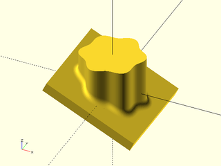
include <BOSL2/std.scad>
include <BOSL2/rounding.scad>
flower = [for(theta=lerpn(0,360,180,endpoint=false))
          (15+1.3*sin(6*theta))*[cos(theta),sin(theta)]];
join_prism(flower,base="plane",length=18, fillet=3,
           n=12, base_T=yrot(25));
yrot(25)cube([50,50,5],anchor=TOP);
Example 6: Next consider attaching the prism to a sphere. You must use a circumscribed sphere to avoid a lip or gap between the sphere and prism. Note that the prism is attached to the sphere's boundary above the origin and projects by the specified length away from the attachment point.
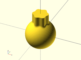
include <BOSL2/std.scad>
include <BOSL2/rounding.scad>
flower = [for(theta=lerpn(0,360,180,endpoint=false))
          (15+1.3*sin(6*theta))*[cos(theta),sin(theta)]];
join_prism(flower,base="sphere",base_r=30, length=18,
           fillet=3, n=12);
spheroid(r=30,circum=true,$fn=64);
Example 7: Rotating using the prism_end_T option rotates around the attachment point. Note that if you rotate too far, some points of the prism will miss the sphere, which is an error.
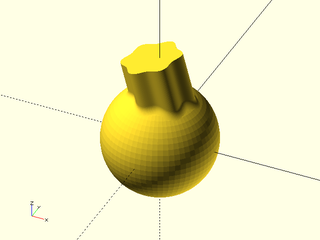
include <BOSL2/std.scad>
include <BOSL2/rounding.scad>
flower = [for(theta=lerpn(0,360,180,endpoint=false))
          (15+1.3*sin(6*theta))*[cos(theta),sin(theta)]];
join_prism(flower,base="sphere",base_r=30, length=18,
           fillet=3, n=12, prism_end_T=yrot(-15));
spheroid(r=30,circum=true,$fn=64);
Example 8: Rotating using the aux_T option rotates around the origin. You could get the same result in this case by rotating the whole model.
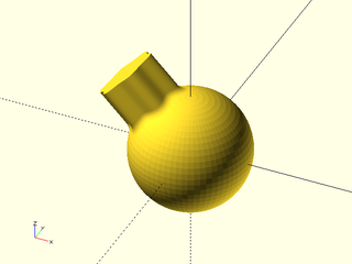
include <BOSL2/std.scad>
include <BOSL2/rounding.scad>
flower = [for(theta=lerpn(0,360,180,endpoint=false))
          (15+1.3*sin(6*theta))*[cos(theta),sin(theta)]];
join_prism(flower,base="sphere",base_r=30, length=18,
           fillet=3, n=12, aux_T=yrot(-45));
spheroid(r=30,circum=true,$fn=64);
Example 9: The origin in the prism cross section always aligns with the origin of the object you attach to. If you want to attach off center, then shift your prism cross section. If you shift too far so that parts of the prism miss the base object then you will get an error.
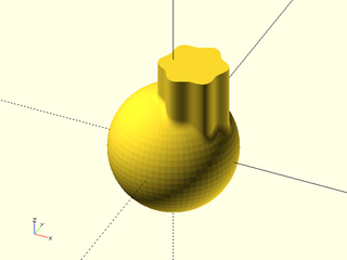
include <BOSL2/std.scad>
include <BOSL2/rounding.scad>
flower = [for(theta=lerpn(0,360,180,endpoint=false))
          (15+1.3*sin(6*theta))*[cos(theta),sin(theta)]];
join_prism(right(10,flower),base="sphere",base_r=30,
           length=18, fillet=3, n=12);
spheroid(r=30,circum=true,$fn=64);
Example 10: The third available base shape is the cylinder.
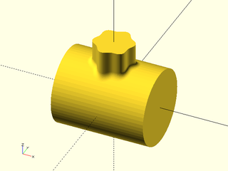
include <BOSL2/std.scad>
include <BOSL2/rounding.scad>
flower = [for(theta=lerpn(0,360,180,endpoint=false))
          (15+1.3*sin(6*theta))*[cos(theta),sin(theta)]];
join_prism(flower,base="cylinder",base_r=30,
           length=18, fillet=4, n=12);
xcyl(r=30,l=75,circum=true,$fn=64);
Example 11: You can rotate the cylinder the same way we rotated the plane.
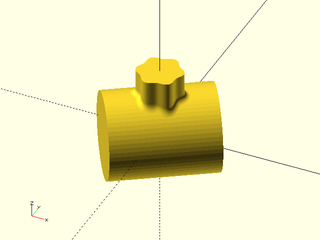
include <BOSL2/std.scad>
include <BOSL2/rounding.scad>
flower = [for(theta=lerpn(0,360,180,endpoint=false))
          (15+1.3*sin(6*theta))*[cos(theta),sin(theta)]];
join_prism(flower,base="cylinder",base_r=30, length=18,
           fillet=4, n=12, base_T=zrot(33));
zrot(33)xcyl(r=30,l=75,circum=true,$fn=64);
Example 12: And you can rotate the prism around its attachment point with prism_end_T
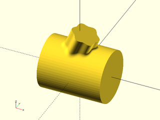
include <BOSL2/std.scad>
include <BOSL2/rounding.scad>
flower = [for(theta=lerpn(0,360,180,endpoint=false))
          (15+1.3*sin(6*theta))*[cos(theta),sin(theta)]];
join_prism(flower,base="cylinder",base_r=30, length=18,
           fillet=4, n=12, prism_end_T=yrot(22));
xcyl(r=30,l=75,circum=true,$fn=64);
Example 13: Or you can rotate the prism around the origin with aux_T
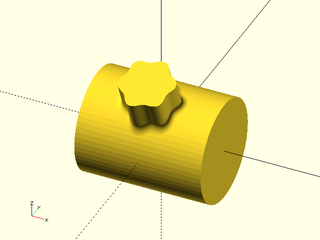
include <BOSL2/std.scad>
include <BOSL2/rounding.scad>
flower = [for(theta=lerpn(0,360,180,endpoint=false))
          (15+1.3*sin(6*theta))*[cos(theta),sin(theta)]];
join_prism(flower,base="cylinder",base_r=30, length=18,
           fillet=4, n=12, aux_T=xrot(22));
xcyl(r=30,l=75,circum=true,$fn=64);
Example 14: Here's a prism where the scale changes
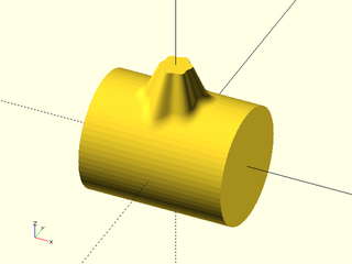
include <BOSL2/std.scad>
include <BOSL2/rounding.scad>
flower = [for(theta=lerpn(0,360,180,endpoint=false))
          (15+1.3*sin(6*theta))*[cos(theta),sin(theta)]];
join_prism(flower,base="cylinder",base_r=30, length=18,
           fillet=4, n=12,scale=.5);
xcyl(r=30,l=75,circum=true,$fn=64);
Example 15: Giving a negative radius attaches to the inside of a sphere or cylinder. Note you want the inscribed cylinder for the inner wall.
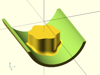
include <BOSL2/std.scad>
include <BOSL2/rounding.scad>
flower = [for(theta=lerpn(0,360,180,endpoint=false))
          (15+1.3*sin(6*theta))*[cos(theta),sin(theta)]];
join_prism(flower,base="cylinder",base_r=-30, length=18,
           fillet=4, n=12);
bottom_half(z=-10)
  tube(ir=30,wall=3,l=74,$fn=64,orient=RIGHT,anchor=CENTER);
Example 16: A hidden problem lurks with concave attachments. The bottom of the prism does not follow the curvature of the base. Here you can see a gap. In some cases you can create a self-intersection in the prism.
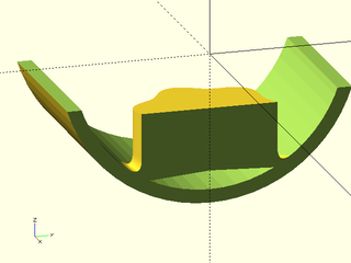
include <BOSL2/std.scad>
include <BOSL2/rounding.scad>
flower = [for(theta=lerpn(0,360,180,endpoint=false))
          (15+1.3*sin(6*theta))*[cos(theta),sin(theta)]];
left_half(){
  join_prism(flower,base="cylinder",base_r=-30, length=18,
             fillet=4, n=12);
  bottom_half(z=-10)
    tube(ir=30,wall=3,l=74,$fn=64,orient=RIGHT,anchor=CENTER);
}
Example 17: The solution to both problems is to increase the overlap parameter, but you may then have excess base that must be differenced or intersected away. In this case, an overlap of 2 is sufficient to eliminate the hole.
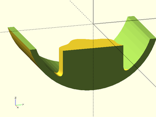
include <BOSL2/std.scad>
include <BOSL2/rounding.scad>
flower = [for(theta=lerpn(0,360,180,endpoint=false))
          (15+1.3*sin(6*theta))*[cos(theta),sin(theta)]];
left_half(){
  join_prism(flower,base="cylinder",base_r=-30, length=18,
             fillet=4, n=12, overlap=2);
  bottom_half(z=-10)
    tube(ir=30,wall=3,l=74,$fn=64,orient=RIGHT,anchor=CENTER);
}
Example 18: Here is an example with a spherical base. This overlap is near the minimum required to eliminate the gap, but it creates a large excess structure around the base of the prism.
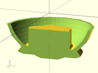
include <BOSL2/std.scad>
include <BOSL2/rounding.scad>
flower = [for(theta=lerpn(0,360,180,endpoint=false))
          (15+1.3*sin(6*theta))*[cos(theta),sin(theta)]];
left_half(){
  join_prism(flower,base="sphere",base_r=-30, length=18,
             fillet=4, n=12, overlap=7);
  bottom_half(z=-10) difference(){
    sphere(r=33,$fn=16);
    sphere(r=30,$fn=64);
  }
}
Example 19: Here is an example with a spherical base. This overlap is near the minimum required to eliminate the gap, but it creates a large excess structure around the base of the prism.
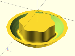
include <BOSL2/std.scad>
include <BOSL2/rounding.scad>
flower = [for(theta=lerpn(0,360,180,endpoint=false))
          (15+1.3*sin(6*theta))*[cos(theta),sin(theta)]];
intersection(){
  union(){
    join_prism(flower,base="sphere",base_r=-30, length=18,
               fillet=4, n=12, overlap=7);
    difference(){
      down(18)cuboid([68,68,30],anchor=TOP);
      sphere(r=30,$fn=64);
    }
  }
  sphere(r=33,$fn=16);
}
Example 20: As before, rotating with aux_T rotates around the origin.
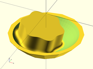
include <BOSL2/std.scad>
include <BOSL2/rounding.scad>
flower = [for(theta=lerpn(0,360,180,endpoint=false))
          (15+1.3*sin(6*theta))*[cos(theta),sin(theta)]];
intersection(){
  union(){
    join_prism(flower,base="sphere",base_r=-30, length=18,
               fillet=4, n=12, overlap=7, aux_T=yrot(13));
    difference(){
      down(18)cuboid([68,68,30],anchor=TOP);
      sphere(r=30,$fn=64);
    }
  }
  sphere(r=33,$fn=16);
}
Example 21: Rotating with prism_end_T rotates around the attachment point. We shrank the prism to allow a significant rotation.
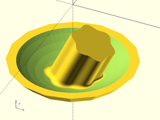
include <BOSL2/std.scad>
include <BOSL2/rounding.scad>
flower = [for(theta=lerpn(0,360,180,endpoint=false))
          (15+1.3*sin(6*theta))*[cos(theta),sin(theta)]];
intersection(){
  union(){
    join_prism(scale(.5,flower),base="sphere",base_r=-30,
               length=18, fillet=2, n=12, overlap=7,
               prism_end_T=yrot(25));
    difference(){
      down(23)cuboid([68,68,30],anchor=TOP);
      sphere(r=30,$fn=64);
    }
  }
  sphere(r=33,$fn=16);
}
Example 22: You can create a prism that crosses the inside of a cylinder or sphere by giving the same negative radius twice and leaving both objects with the same center, as shown here.
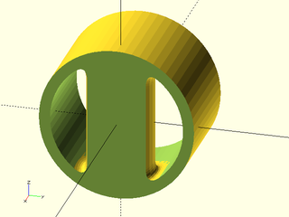
include <BOSL2/std.scad>
include <BOSL2/rounding.scad>
left_half(x=7){
  join_prism(circle(r=15),base="cylinder",base_r=-30, n=12,
             aux="cylinder", aux_r=-30, fillet=8, overlap=3);
  tube(ir=30,wall=5,l=74,$fn=64,orient=RIGHT,anchor=CENTER);
}
Example 23: Here's a similar example with a plane for the auxiliary object. Note that we observe the 1 unit overlap on the top surface.
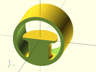
include <BOSL2/std.scad>
include <BOSL2/rounding.scad>
left_half(x=7){
  join_prism(circle(r=15),base="cylinder",base_r=-30,
             aux="plane", fillet=8, n=12, overlap=3);
  tube(ir=30,wall=5,l=74,$fn=64,orient=RIGHT,anchor=CENTER);
}
Example 24: We have tweaked the previous example just slightly by lowering the height of the plane. The result is a bit of a surprise: the prism flips upside down! This happens because there is an ambiguity in creating a prism between a plane and the inside of the cylinder. By default, this ambiguity is resolved by choosing the longer prism.
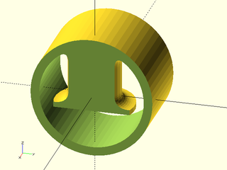
include <BOSL2/std.scad>
include <BOSL2/rounding.scad>
left_half(x=7){
  join_prism(circle(r=15),base="cylinder",base_r=-30, n=12,
             aux="plane", aux_T=down(5), fillet=8, overlap=3);
  tube(ir=30,wall=5,l=74,$fn=64,orient=RIGHT,anchor=CENTER);
}
Example 25: Adding short=true resolves the ambiguity of which prism to construct in the other way, by choosing the shorter option.
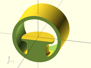
include <BOSL2/std.scad>
include <BOSL2/rounding.scad>
left_half(x=7){
  join_prism(circle(r=15),base="cylinder",base_r=-30,
             aux="plane", aux_T=down(5), fillet=8,
             n=12, overlap=3, short=true);
  tube(ir=30,wall=5,l=74,$fn=64,orient=RIGHT,anchor=CENTER);
}
Example 26: The problem does not arise in this case because the auxiliary object only allows one possible way to make the connection.
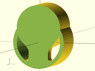
include <BOSL2/std.scad>
include <BOSL2/rounding.scad>
left_half(x=7){
  join_prism(circle(r=15),base="cylinder",base_r=-30,
             aux="cylinder", aux_r=30, aux_T=up(20),
             fillet=8, n=12, overlap=3);
  tube(ir=30,wall=5,l=74,$fn=64,orient=RIGHT,anchor=CENTER);
  up(20)xcyl(r=30,l=74,$fn=64);
}
Example 27: When the aux cylinder is inside the base cylinder we can select the two options, shown here as red for the default and blue for the short=true case.
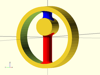
include <BOSL2/std.scad>
include <BOSL2/rounding.scad>
color("red")
  join_prism(circle(r=5),base="cylinder",base_r=-30,
             aux="cyl",aux_r=10, aux_T=up(12), fillet=4,
              n=12, overlap=3, short=false);
color("blue")
  join_prism(circle(r=5),base="cylinder",base_r=-30,
             aux="cyl",aux_r=10, aux_T=up(12), fillet=4,
             n=12, overlap=3, short=true);
tube(ir=30,wall=5,$fn=64,l=18,orient=RIGHT,anchor=CENTER);
up(12)xcyl(r=10, circum=true, l=18);
Example 28: The same thing is true when you use a negative radius for the aux cylinder. This is the default long case.
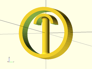
include <BOSL2/std.scad>
include <BOSL2/rounding.scad>
join_prism(circle(r=5,$fn=64),base="cylinder",base_r=-30,
           aux="cyl",aux_r=-10, aux_T=up(12), fillet=4,
           n=12, overlap=3, short=false);
tube(ir=30,wall=5,l=24,$fn=64,orient=RIGHT,anchor=CENTER);
up(12) top_half()
   tube(ir=10,wall=4,l=24,$fn=64,orient=RIGHT,anchor=CENTER);
Example 29: And here is the short case:
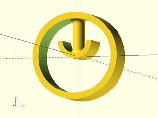
include <BOSL2/std.scad>
include <BOSL2/rounding.scad>
join_prism(circle(r=5,$fn=64),base="cylinder",base_r=-30,
           aux="cyl",aux_r=-10, aux_T=up(12), fillet=4,
           n=12, overlap=3, short=true);
tube(ir=30,l=24,wall=5,$fn=64,orient=RIGHT,anchor=CENTER);
up(12) bottom_half()
  tube(ir=10,wall=4,l=24,$fn=64,orient=RIGHT,anchor=CENTER);
Example 30: Another example where the cylinders overlap, with the long case here:
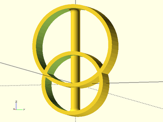
include <BOSL2/std.scad>
include <BOSL2/rounding.scad>
auxT=up(40);
join_prism(circle(r=5,$fn=64),base="cylinder",base_r=-30,
           aux="cyl",aux_r=-40, aux_T=auxT, fillet=4,
           n=12, overlap=3, short=false);
tube(ir=30,wall=4,l=24,$fn=64,orient=RIGHT,anchor=CENTER);
multmatrix(auxT)
  tube(ir=40,wall=4,l=24,$fn=64,orient=RIGHT,anchor=CENTER);
Example 31: And the short case:
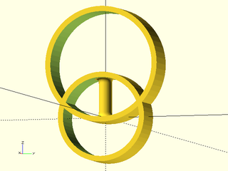
include <BOSL2/std.scad>
include <BOSL2/rounding.scad>
auxT=up(40);
join_prism(circle(r=5,$fn=64),base="cylinder",base_r=-30,
           aux="cyl",aux_r=-40, aux_T=auxT, fillet=4,
           n=12, overlap=3, short=true);
tube(ir=30,wall=4,l=24,$fn=64,orient=RIGHT,anchor=CENTER);
multmatrix(auxT)
  tube(ir=40,wall=4,l=24,$fn=64,orient=RIGHT,anchor=CENTER);
Example 32: Many of the preceeding examples feature a prism with a concave shape cross section. Concave regions can limit the amount of rounding that is possible. This occurs because the algorithm is not able to handle a fillet that intersects itself. Fillets on a convex prism always grow larger as they move away from the prism, so they cannot self intersect. This means that you can make the fillet as big as will fit on the base shape. The fillet will fail to fit if the tangent plane to the base at the fillet distance from the prism fails to intersect the prism. Here is an extreme example, almost the largest possible fillet to the convex elliptical convex prism.
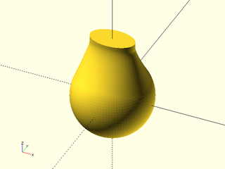
include <BOSL2/std.scad>
include <BOSL2/rounding.scad>
ellipse = ellipse([17,10],$fn=164);
join_prism(ellipse,base="sphere",base_r=30, length=18,
           fillet=18, n=25, overlap=1);
spheroid(r=30,circum=true, $fn=96);
Example 33: This example shows a failed rounding attempt where the result is self-intersecting. Using the debug=true option makes it possible to view the result to understand what went wrong. Note that the concave corners have a crease where the fillet crosses itself. The error message will advise you to decrease the size of the fillet. You can also fix the problem by making your concave curves shallower.
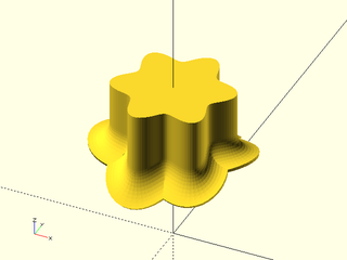
include <BOSL2/std.scad>
include <BOSL2/rounding.scad>
flower = [for(theta=lerpn(0,360,180,endpoint=false))
          (15+2.5*sin(6*theta))*[cos(theta),sin(theta)]];
join_prism(flower,base="cylinder",base_r=30, length=18,
           fillet=6, n=12, debug=true);
Example 34: Your prism needs to be finely sampled enough to follow the contour of the base you are attaching it to. If it is not, you get a result like this. The fillet joints the prism smoothly, but makes a poor transition to the sphere.
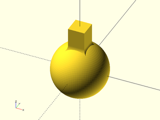
include <BOSL2/std.scad>
include <BOSL2/rounding.scad>
sq = rect(15);
join_prism(sq, base="sphere", base_r=25,
           length=18, fillet=4, n=12);
spheroid(r=25, circum=true, $fn=96);
Example 35: To fix the problem, you must subdivide the polygon that defines the prism. But note that the join_prism method works poorly at sharp corners.
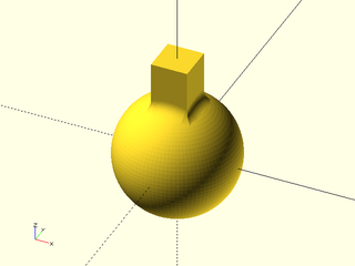
include <BOSL2/std.scad>
include <BOSL2/rounding.scad>
sq = subdivide_path(rect(15),n=64);
join_prism(sq, base="sphere", base_r=25,
           length=18, fillet=4, n=12);
spheroid(r=25, circum=true,$fn=96);
Example 36: In the previous example, a small rounding of the prism corners produces a nicer result.

include <BOSL2/std.scad>
include <BOSL2/rounding.scad>
sq = subdivide_path(
       round_corners(rect(15),cut=.5,$fn=32),
       n=128);
join_prism(sq, base="sphere", base_r=25,
           length=18, fillet=4, n=12);
spheroid(r=25, circum=true,$fn=96);
Example 37: The final option for specifying the base is to use an arbitrary prism, specified by a polygon. Note that the base prism is oriented to the RIGHT, so the attached prism remains Z oriented.
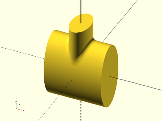
include <BOSL2/std.scad>
include <BOSL2/rounding.scad>
ellipse = ellipse([17,10],$fn=164);
join_prism(zrot(90,ellipse), base=2*ellipse, length=19,
           fillet=4, n=12);
linear_sweep(2*ellipse,height=60, center=true, orient=RIGHT);
Example 38: As usual, you can rotate around the attachment point using prism_end_T.
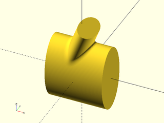
include <BOSL2/std.scad>
include <BOSL2/rounding.scad>
ellipse = ellipse([17,10],$fn=164);
join_prism(zrot(90,ellipse), base=2*ellipse, length=19,
           fillet=4, n=12, prism_end_T=yrot(22));
linear_sweep(2*ellipse,height=60, center=true, orient=RIGHT);
Example 39: And you can rotate around the origin with aux_T.
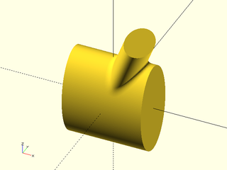
include <BOSL2/std.scad>
include <BOSL2/rounding.scad>
ellipse = ellipse([17,10],$fn=164);
join_prism(zrot(90,ellipse), base=2*ellipse, length=19,
           fillet=4, n=12, aux_T=yrot(22));
linear_sweep(2*ellipse,height=60, center=true, orient=RIGHT);
Example 40: The base prism can be a more complicated shape.
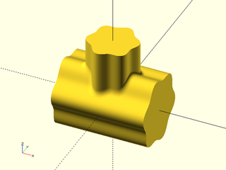
include <BOSL2/std.scad>
include <BOSL2/rounding.scad>
flower = [for(theta=lerpn(0,360,180,endpoint=false))
          (15+1.3*sin(6*theta))*[cos(theta),sin(theta)]];
join_prism(flower,base=1.4*flower, fillet=3,
           n=15, length=20);
linear_sweep(1.4*flower,height=60,center=true,
             convexity=10,orient=RIGHT);
Example 41: Here's an example with both prism_end_T and aux_T
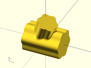
include <BOSL2/std.scad>
include <BOSL2/rounding.scad>
flower = [for(theta=lerpn(0,360,180,endpoint=false))
          (15+1.3*sin(6*theta))*[cos(theta),sin(theta)]];
join_prism(flower,base=1.4*flower, length=20,
           prism_end_T=yrot(20),aux_T=xrot(10),
           fillet=3, n=25);
linear_sweep(1.4*flower,height=60,center=true,
             convexity=10,orient=RIGHT);
Example 42: Instead of terminating your prism in a flat face perpendicular to its axis you can attach it to a second object. The simplest case is to connect to planar attachments. When connecting to a second object you must position and orient the second object using aux_T, which is now allowed to be a rotation and translation operator. The length parameter is no longer allowed.
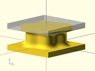
include <BOSL2/std.scad>
include <BOSL2/rounding.scad>
flower = [for(theta=lerpn(0,360,180,endpoint=false))
          (15+1.3*sin(6*theta))*[cos(theta),sin(theta)]];
join_prism(flower,base="plane", fillet=4, n=12,
           aux="plane", aux_T=up(12));
%up(12)cuboid([40,40,4],anchor=BOT);
cuboid([40,40,4],anchor=TOP);
Example 43: Here's an example where the second object is rotated. Note that the prism will go from the origin to the origin point of the object. In this case because the rotation is applied first, the prism is vertical.
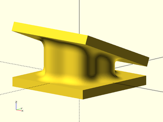
include <BOSL2/std.scad>
include <BOSL2/rounding.scad>
flower = [for(theta=lerpn(0,360,180,endpoint=false))
          (15+1.3*sin(6*theta))*[cos(theta),sin(theta)]];
aux_T = up(12)*xrot(-22);
join_prism(flower,base="plane",fillet=4, n=12,
           aux="plane", aux_T=aux_T);
multmatrix(aux_T)cuboid([42,42,4],anchor=BOT);
cuboid([40,40,4],anchor=TOP);
Example 44: In this example, the aux_T transform moves the centerpoint (origin) of the aux object, and the resulting prism connects centerpoints, so it is no longer vertical.
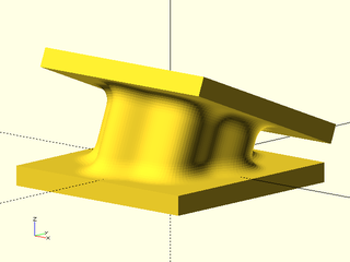
include <BOSL2/std.scad>
include <BOSL2/rounding.scad>
flower = [for(theta=lerpn(0,360,180,endpoint=false))
          (15+1.3*sin(6*theta))*[cos(theta),sin(theta)]];
aux_T = xrot(-22)*up(12);
join_prism(flower,base="plane",fillet=4, n=12,
           aux="plane", aux_T=aux_T);
multmatrix(aux_T)cuboid([42,42,4],anchor=BOT);
cuboid([43,43,4],anchor=TOP);
Example 45: You can combine with base_T
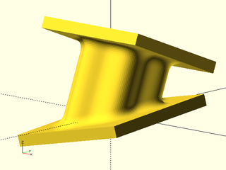
include <BOSL2/std.scad>
include <BOSL2/rounding.scad>
flower = [for(theta=lerpn(0,360,180,endpoint=false))
          (15+1.3*sin(6*theta))*[cos(theta),sin(theta)]];
aux_T = xrot(-22)*up(22);
base_T = xrot(5)*yrot(-12);
join_prism(flower,base="plane",base_T=base_T,
           aux="plane",aux_T=aux_T, fillet=4, n=12);
multmatrix(aux_T)cuboid([42,42,4],anchor=BOT);
multmatrix(base_T)cuboid([45,45,4],anchor=TOP);
Example 46: Using prism_end_T shifts the prism's end without tilting the plane, so the prism ends are not perpendicular to the prism axis.
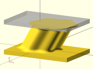
include <BOSL2/std.scad>
include <BOSL2/rounding.scad>
flower = [for(theta=lerpn(0,360,180,endpoint=false))
          (15+1.3*sin(6*theta))*[cos(theta),sin(theta)]];
join_prism(flower,base="plane", prism_end_T=right(14),
           aux="plane",aux_T=up(24), fillet=4, n=12);
right(7){
  %up(24)cuboid([65,42,4],anchor=BOT);
  cuboid([65,42,4],anchor=TOP);
}
Example 47: Negative fillets give roundovers and are pemitted only for joints to planes. Note that overlap defaults to zero for negative fillets.
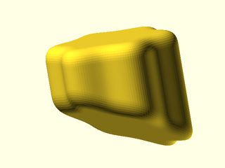
include <BOSL2/std.scad>
include <BOSL2/rounding.scad>
flower = [for(theta=lerpn(0,360,180,endpoint=false))
          (15+1.3*sin(6*theta))*[cos(theta),sin(theta)]];
aux_T = xrot(-22)*up(22);
base_T = xrot(5)*yrot(-12);
join_prism(flower,base="plane",base_T=base_T,
           aux="plane", aux_T=aux_T, fillet=-4,n=12);
Example 48: It works the same way with the other shapes, but make sure you move the shapes far enough apart that there is room for a prism.
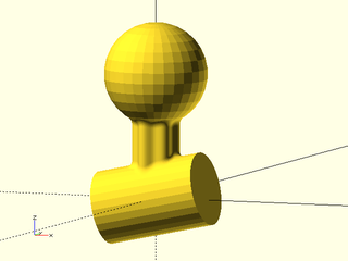
include <BOSL2/std.scad>
include <BOSL2/rounding.scad>
flower = [for(theta=lerpn(0,360,180,endpoint=false))
          (15+1.3*sin(6*theta))*[cos(theta),sin(theta)]];
aux_T = up(85);
base_T = xrot(5)*yrot(-12);
join_prism(flower,base="cylinder",base_r=25, fillet=4, n=12,
           aux="sphere",aux_r=35,base_T=base_T, aux_T=aux_T);
multmatrix(aux_T)spheroid(35,circum=true);
multmatrix(base_T)xcyl(l=75,r=25,circum=true);
Example 49: Here we translate the sphere to the right and the prism goes with it
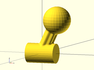
include <BOSL2/std.scad>
include <BOSL2/rounding.scad>
flower = [for(theta=lerpn(0,360,180,endpoint=false))
          (15+1.3*sin(6*theta))*[cos(theta),sin(theta)]];
aux_T = right(40)*up(85);
join_prism(flower,base="cylinder",base_r=25, n=12,
           aux="sphere",aux_r=35, aux_T=aux_T, fillet=4);
multmatrix(aux_T)spheroid(35,circum=true);
xcyl(l=75,r=25,circum=true);
Example 50: This is the previous example with the prism_end_T transformation used to shift the far end of the prism away from the sphere center. Note that prism_end_T can be any transformation, but it just acts on the location of the prism endpoint to shift the direction the prism points.
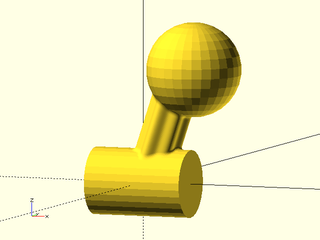
include <BOSL2/std.scad>
include <BOSL2/rounding.scad>
flower = [for(theta=lerpn(0,360,180,endpoint=false))
          (15+1.3*sin(6*theta))*[cos(theta),sin(theta)]];
aux_T = right(40)*up(85);
join_prism(flower,base="cylinder",base_r=25,
           prism_end_T=left(4), fillet=3, n=12,
           aux="sphere",aux_r=35, aux_T=aux_T);
multmatrix(aux_T)spheroid(35,circum=true);
xcyl(l=75,r=25,circum=true);
Example 51: Here the base is a cylinder but the auxilary object is a generic prism, and the joiner prism has a scale factor.
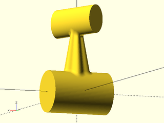
include <BOSL2/std.scad>
include <BOSL2/rounding.scad>
flower = [for(theta=lerpn(0,360,180,endpoint=false))
          (15+1.3*sin(6*theta))*[cos(theta),sin(theta)]];
aux_T = up(85)*zrot(-75);
ellipse = ellipse([17,10],$fn=164);
join_prism(flower,base="cylinder",base_r=25,
           fillet=4, n=12,
           aux=ellipse, aux_T=aux_T,scale=.5);
multmatrix(aux_T)
  linear_sweep(ellipse,orient=RIGHT,height=75,center=true);
xcyl(l=75,r=25,circum=true,$fn=100);
Example 52: Base and aux are both a general prism in this case.
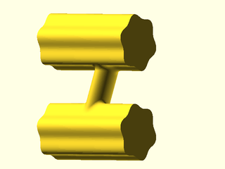
include <BOSL2/std.scad>
include <BOSL2/rounding.scad>
ellipse = ellipse([10,17]/2,$fn=96);
flower = [for(theta=lerpn(0,360,180,endpoint=false))
          (15+1.3*sin(6*theta))*[cos(theta),sin(theta)]];
aux_T=up(50);
join_prism(ellipse,base=flower,aux_T=aux_T,aux=flower,
           fillet=3, n=12, prism_end_T=right(9));
multmatrix(aux_T)
  linear_sweep(flower,height=60,center=true,orient=RIGHT);
linear_sweep(flower,height=60,center=true,orient=RIGHT);
Example 53: Shifting the joiner prism forward brings it close to a steeply curved edge of the auxiliary prism at the top. Note that a funny looking bump with a sharp corner has appeared in the fillet. This bump/corner is a result of the uniform filleting method running out of space. If we move the joiner prism farther forward, the algorithm fails completely.

include <BOSL2/std.scad>
include <BOSL2/rounding.scad>
ellipse = ellipse([10,17]/2,$fn=96);
flower = [for(theta=lerpn(0,360,180,endpoint=false))
          (15+1.3*sin(6*theta))*[cos(theta),sin(theta)]];
aux_T=up(50);
join_prism(ellipse,base=flower,aux_T=aux_T,aux=flower,
           fillet=3, n=12, prism_end_T=fwd(1.6));
multmatrix(aux_T)
  linear_sweep(flower,height=60,center=true,orient=RIGHT);
linear_sweep(flower,height=60,center=true,orient=RIGHT);
Example 54: This is the same example as above but with uniform turned off. Note how the line the fillet makes on the joiner prism is not uniform, but the overall curved shape is more pleasing than the previous result, and we can bring the joiner prism a little farther forward and still construct a model.
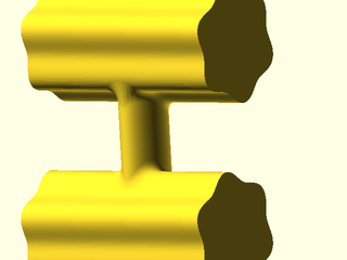
include <BOSL2/std.scad>
include <BOSL2/rounding.scad>
ellipse = ellipse([10,17]/2,$fn=96);
flower = [for(theta=lerpn(0,360,180,endpoint=false))
          (15+1.3*sin(6*theta))*[cos(theta),sin(theta)]];
aux_T=up(50);
join_prism(ellipse,base=flower,aux_T=aux_T,aux=flower,
           fillet=3, n=12, prism_end_T=fwd(1.7),
           uniform=false);
multmatrix(aux_T)
  linear_sweep(flower,height=60,center=true,orient=RIGHT);
linear_sweep(flower,height=60,center=true,orient=RIGHT);
Example 55: Positioning a joiner prism as an attachment
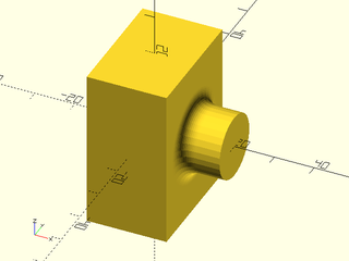
include <BOSL2/std.scad>
include <BOSL2/rounding.scad>
cuboid([20,30,40])
  attach(RIGHT,"root")
    join_prism(circle(r=8,$fn=32),
               l=10, base="plane", fillet=4);