drawing.scad
This file includes stroke(), which converts a path into a geometric object, like drawing with a pen. It even works on three-dimensional paths. You can make a dashed line or add arrow heads. The turtle() function provides a turtle graphics style approach for producing paths. The arc() function produces arc paths, and helix() produces helical paths.
To use, add the following lines to the beginning of your file:
include <BOSL2/std.scad>
-
-
stroke()– Draws a line along a path or region boundry. [Geom] -
dashed_stroke()– Draws a dashed line along a path or region boundry. [Geom] [PathList]
-
-
-
arc()– Draws a 2D pie-slice or returns 2D or 3D path forming an arc. [Geom] [Path] -
catenary()– Returns a 2D Catenary chain or arch path. [Path] -
helix()– Creates a 2d spiral or 3d helical path. [Path] -
turtle()– Uses turtle graphics to generate a 2D path. [Path]
-
-
-
debug_polygon()– Draws an annotated polygon. [Geom]
-
Synopsis: Draws a line along a path or region boundry. [Geom]
Topics: Paths (2D), Paths (3D), Drawing Tools
See Also: dashed_stroke(), offset_stroke(), path_sweep()
Usage:
- stroke(path, [width], [closed], [endcaps], [endcap_width], [endcap_length], [endcap_extent], [trim]);
- stroke(path, [width], [closed], [endcap1], [endcap2], [endcap_width1], [endcap_width2], [endcap_length1], [endcap_length2], [endcap_extent1], [endcap_extent2], [trim1], [trim2]);
Description:
Draws a 2D or 3D path with a given line width. Joints and each endcap can be replaced with
various marker shapes, and can be assigned different colors. If passed a region instead of
a path, draws each path in the region as a closed polygon by default. If closed=false is
given with a region or list of paths, then each path is drawn without the closing line segment.
When drawing a closed path or region, there are no endcaps, so you cannot give the endcap parameters.
To facilitate debugging, stroke() accepts "paths" that have a single point. These are drawn with
the style of endcap1, but have their own scale parameter, singleton_scale, which defaults to 2
so that singleton dots with endcap "round" are clearly visible.
In 2d the stroke module works by creating a sequence of rectangles (or trapezoids if line width varies) and
filling in the gaps with rounded wedges. This is fast and produces a good result. In 3d the modules
creates a cylinders (or cones) and fills the gaps with rounded wedges made using rotate_extrude. This process will be slow for
long paths due to the 3d unions, and the faces on sequential cylinders may not line up. In many cases, path_sweep() will be
a better choice, both running faster and producing superior output, when working in three dimensions.
Figure 1: Endcap Types

Arguments:
| By Position | What it does |
|---|---|
path |
The path to draw along. |
width |
The width of the line to draw. If given as a list of widths, (one for each path point), draws the line with varying thickness to each point. |
closed |
If true, draw an additional line from the end of the path to the start. |
joints |
Specifies the joint shape for each joint of the line. If a 2D polygon is given, use that to draw custom joints. |
endcaps |
Specifies the endcap type for both ends of the line. If a 2D polygon is given, use that to draw custom endcaps. |
endcap1 |
Specifies the endcap type for the start of the line. If a 2D polygon is given, use that to draw a custom endcap. |
endcap2 |
Specifies the endcap type for the end of the line. If a 2D polygon is given, use that to draw a custom endcap. |
dots |
Specifies both the endcap and joint types with one argument. If given true, sets both to "dot". If a 2D polygon is given, uses that to draw custom dots. |
joint_width |
Some joint shapes are wider than the line. This specifies the width of the shape, in multiples of the line width. |
endcap_width |
Some endcap types are wider than the line. This specifies the size of endcaps, in multiples of the line width. |
endcap_width1 |
This specifies the size of starting endcap, in multiples of the line width. |
endcap_width2 |
This specifies the size of ending endcap, in multiples of the line width. |
dots_width |
This specifies the size of the joints and endcaps, in multiples of the line width. |
joint_length |
Length of joint shape, in multiples of the line width. |
endcap_length |
Length of endcaps, in multiples of the line width. |
endcap_length1 |
Length of starting endcap, in multiples of the line width. |
endcap_length2 |
Length of ending endcap, in multiples of the line width. |
dots_length |
Length of both joints and endcaps, in multiples of the line width. |
joint_extent |
Extents length of joint shape, in multiples of the line width. |
endcap_extent |
Extents length of endcaps, in multiples of the line width. |
endcap_extent1 |
Extents length of starting endcap, in multiples of the line width. |
endcap_extent2 |
Extents length of ending endcap, in multiples of the line width. |
dots_extent |
Extents length of both joints and endcaps, in multiples of the line width. |
joint_angle |
Extra rotation given to joint shapes, in degrees. If not given, the shapes are fully spun (for 3D lines). |
endcap_angle |
Extra rotation given to endcaps, in degrees. If not given, the endcaps are fully spun (for 3D lines). |
endcap_angle1 |
Extra rotation given to a starting endcap, in degrees. If not given, the endcap is fully spun (for 3D lines). |
endcap_angle2 |
Extra rotation given to a ending endcap, in degrees. If not given, the endcap is fully spun (for 3D lines). |
dots_angle |
Extra rotation given to both joints and endcaps, in degrees. If not given, the endcap is fully spun (for 3D lines). |
trim |
Trim the the start and end line segments by this much, to keep them from interfering with custom endcaps. |
trim1 |
Trim the the starting line segment by this much, to keep it from interfering with a custom endcap. |
trim2 |
Trim the the ending line segment by this much, to keep it from interfering with a custom endcap. |
color |
If given, sets the color of the line segments, joints and endcap. |
endcap_color |
If given, sets the color of both endcaps. Overrides color= and dots_color=. |
endcap_color1 |
If give, sets the color of the starting endcap. Overrides color=, dots_color=, and endcap_color=. |
endcap_color2 |
If given, sets the color of the ending endcap. Overrides color=, dots_color=, and endcap_color=. |
joint_color |
If given, sets the color of the joints. Overrides color= and dots_color=. |
dots_color |
If given, sets the color of the endcaps and joints. Overrides color=. |
singleton_scale |
Change the scale of the endcap shape drawn for singleton paths. Default: 2. |
convexity |
Max number of times a line could intersect a wall of an endcap. |
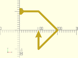
Example 1: Drawing a Path
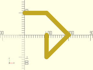
include <BOSL2/std.scad>
path = [[0,100], [100,100], [200,0], [100,-100], [100,0]];
stroke(path, width=20);
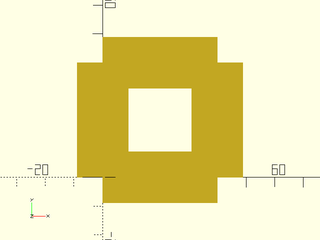
Example 2: Closing a Path
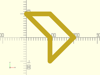
include <BOSL2/std.scad>
path = [[0,100], [100,100], [200,0], [100,-100], [100,0]];
stroke(path, width=20, closed=true);
Example 3: Fancy Arrow Endcaps
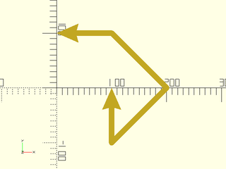
include <BOSL2/std.scad>
path = [[0,100], [100,100], [200,0], [100,-100], [100,0]];
stroke(path, width=10, endcaps="arrow2");
Example 4: Modified Fancy Arrow Endcaps
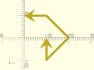
include <BOSL2/std.scad>
path = [[0,100], [100,100], [200,0], [100,-100], [100,0]];
stroke(path, width=10, endcaps="arrow2", endcap_width=6, endcap_length=3, endcap_extent=2);
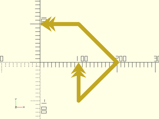
Example 5: Mixed Endcaps
include <BOSL2/std.scad>
path = [[0,100], [100,100], [200,0], [100,-100], [100,0]];
stroke(path, width=10, endcap1="tail2", endcap2="arrow2");
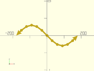
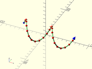
Example 6: Plotting Points. Setting endcap_angle to zero results in the weird arrow orientation.
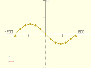
include <BOSL2/std.scad>
path = [for (a=[0:30:360]) [a-180, 60*sin(a)]];
stroke(path, width=3, joints="diamond", endcaps="arrow2", endcap_angle=0, endcap_width=5, joint_angle=0, joint_width=5);
Example 7: Default joint gives curves along outside corners of the path:
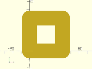
include <BOSL2/std.scad>
stroke([square(40)], width=18);
Example 8: Setting joints="square" gives flat outside corners
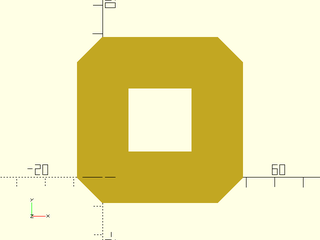
include <BOSL2/std.scad>
stroke([square(40)], width=18, joints="square");
Example 9: Setting joints="butt" does not draw any transitions, just rectangular strokes for each segment, meeting at their centers:
include <BOSL2/std.scad>
stroke([square(40)], width=18, joints="butt");
Example 10: Joints and Endcaps
include <BOSL2/std.scad>
path = [for (a=[0:30:360]) [a-180, 60*sin(a)]];
stroke(path, width=8, joints="dot", endcaps="arrow2");
Example 11: Custom Endcap Shapes
include <BOSL2/std.scad>
path = [[0,100], [100,100], [200,0], [100,-100], [100,0]];
arrow = [[0,0], [2,-3], [0.5,-2.3], [2,-4], [0.5,-3.5], [-0.5,-3.5], [-2,-4], [-0.5,-2.3], [-2,-3]];
stroke(path, width=10, trim=3.5, endcaps=arrow);
Example 12: Variable Line Width
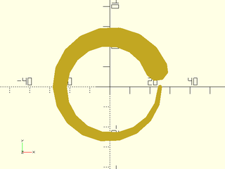
include <BOSL2/std.scad>
path = circle(d=50,$fn=18);
widths = [for (i=idx(path)) 10*i/len(path)+2];
stroke(path,width=widths,$fa=1,$fs=1);
Example 13: 3D Path with Endcaps
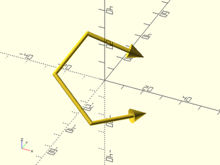
include <BOSL2/std.scad>
path = rot([15,30,0], p=path3d(pentagon(d=50)));
stroke(path, width=2, endcaps="arrow2", $fn=18);
Example 14: 3D Path with Flat Endcaps
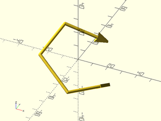
include <BOSL2/std.scad>
path = rot([15,30,0], p=path3d(pentagon(d=50)));
stroke(path, width=2, endcaps="arrow2", endcap_angle=0, $fn=18);
Example 15: 3D Path with Mixed Endcaps
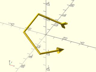
include <BOSL2/std.scad>
path = rot([15,30,0], p=path3d(pentagon(d=50)));
stroke(path, width=2, endcap1="arrow2", endcap2="tail", endcap_angle2=0, $fn=18);
Example 16: 3D Path with Joints and Endcaps
include <BOSL2/std.scad>
path = [for (i=[0:10:360]) [(i-180)/2,20*cos(3*i),20*sin(3*i)]];
stroke(path, width=2, joints="dot", endcap1="round", endcap2="arrow2", joint_width=2.0, endcap_width2=3, $fn=18);
Example 17: Coloring Lines, Joints, and Endcaps
include <BOSL2/std.scad>
path = [for (i=[0:15:360]) [(i-180)/3,20*cos(2*i),20*sin(2*i)]];
stroke(
    path, width=2, joints="dot", endcap1="dot", endcap2="arrow2",
    color="lightgreen", joint_color="red", endcap_color="blue",
    joint_width=2.0, endcap_width2=3, $fn=18
);
Example 18: Simplified Plotting
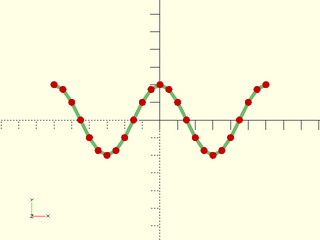
include <BOSL2/std.scad>
path = [for (i=[0:15:360]) [(i-180)/3,20*cos(2*i)]];
stroke(path, width=2, dots=true, color="lightgreen", dots_color="red", $fn=18);
Example 19: Drawing a Region
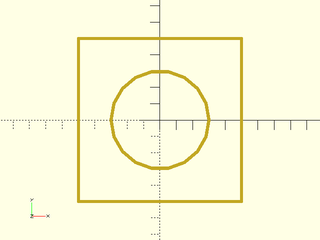
include <BOSL2/std.scad>
rgn = [square(100,center=true), circle(d=60,$fn=18)];
stroke(rgn, width=2);
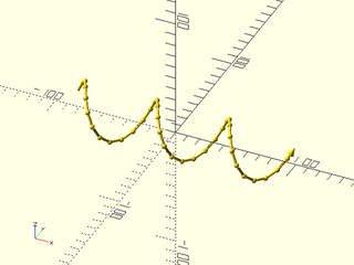
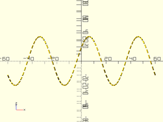
Example 20: Drawing a List of Lines
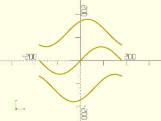
include <BOSL2/std.scad>
paths = [
    for (y=[-60:60:60]) [
        for (a=[-180:15:180])
        [a, 2*y+60*sin(a+y)]
    ]
];
stroke(paths, closed=false, width=5);
Example 21: Paths with a singleton. Note that the singleton is not a single point, but a list containing a single point.
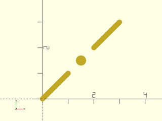
include <BOSL2/std.scad>
stroke([
        [[0,0],[1,1]],
        [[1.5,1.5]],
        [[2,2],[3,3]]
       ],width=0.2,closed=false,$fn=16);
Synopsis: Draws a dashed line along a path or region boundry. [Geom] [PathList]
Topics: Paths, Drawing Tools
See Also: stroke(), path_cut()
Usage: As a Module
- dashed_stroke(path, dashpat, [width=], [closed=]);
Usage: As a Function
- dashes = dashed_stroke(path, dashpat, [closed=]);
Description:
Given a path (or region) and a dash pattern, creates a dashed line that follows that path or region boundary with the given dash pattern.
- When called as a function, returns a list of dash sub-paths.
- When called as a module, draws all those subpaths using
stroke().
When called as a module the dash pattern is multiplied by the line width. When called as a function the dash pattern applies as you specify it.
Arguments:
| By Position | What it does |
|---|---|
path |
The path or region to subdivide into dashes. |
dashpat |
A list of alternating dash lengths and space lengths for the dash pattern. This will be scaled by the width of the line. |
| By Name | What it does |
|---|---|
width |
The width of the dashed line to draw. Module only. Default: 1 |
closed |
If true, treat path as a closed polygon. Default: false |
fit |
If true, shrink or stretch the dash pattern so that the path ends ofter a logical dash. Default: true |
roundcaps |
(Module only) If true, draws dashes with rounded caps. This often looks better. Default: true |
mindash |
(Function only) Specifies the minimal dash length to return at the end of a path when fit is false. Default: 0.5 |
Example 1: Open Path
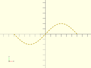
include <BOSL2/std.scad>
path = [for (a=[-180:10:180]) [a/3,20*sin(a)]];
dashed_stroke(path, [3,2], width=1);
Example 2: Closed Polygon
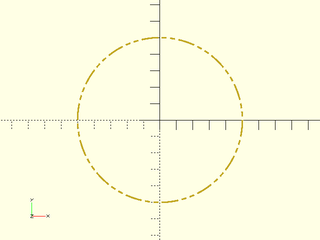
include <BOSL2/std.scad>
path = circle(d=100,$fn=72);
dashpat = [10,2, 3,2, 3,2];
dashed_stroke(path, dashpat, width=1, closed=true);
Example 3: 3D Dashed Path
include <BOSL2/std.scad>
path = [for (a=[-180:5:180]) [a/3, 20*cos(3*a), 20*sin(3*a)]];
dashed_stroke(path, [3,2], width=1);
Synopsis: Draws a 2D pie-slice or returns 2D or 3D path forming an arc. [Geom] [Path]
Topics: Paths (2D), Paths (3D), Shapes (2D), Path Generators
See Also: pie_slice(), stroke(), ring()
Usage: 2D arc from 0º to angle degrees.
- path=arc(n, r|d=, angle);
Usage: 2D arc from START to END degrees.
- path=arc(n, r|d=, angle=[START,END]);
Usage: 2D arc from start to start+angle degrees.
- path=arc(n, r|d=, start=, angle=);
Usage: 2D circle segment by width and thickness, starting and ending on the X axis.
- path=arc(n, width=, thickness=);
Usage: Shortest 2D or 3D arc around centerpoint cp, starting at P0 and ending on the vector pointing from cp to P1.
- path=arc(n, cp=, points=[P0,P1], [long=], [cw=], [ccw=]);
Usage: 2D or 3D arc, starting at P0, passing through P1 and ending at P2.
- path=arc(n, points=[P0,P1,P2]);
Usage: 2D or 3D arc, fron tangent point on segment [P0,P1] to the tangent point on segment [P1,P2].
- path=arc(n, corner=[P0,P1,P2], r=);
Usage: Create a wedge using any other arc parameters
- path=arc(wedge=true,...)
Usage: as module
- arc(...) [ATTACHMENTS];
Description:
If called as a function, returns a 2D or 3D path forming an arc. If wedge is true, the centerpoint of the arc appears as the first point in the result.
If called as a module, creates a 2D arc polygon or pie slice shape.
Arguments:
| By Position | What it does |
|---|---|
n |
Number of vertices to form the arc curve from. |
r |
Radius of the arc. |
angle |
If a scalar, specifies the end angle in degrees (relative to start parameter). If a vector of two scalars, specifies start and end angles. |
| By Name | What it does |
|---|---|
d |
Diameter of the arc. |
cp |
Centerpoint of arc. |
points |
Points on the arc. |
corner |
A path of two segments to fit an arc tangent to. |
long |
if given with cp and points takes the long arc instead of the default short arc. Default: false |
cw |
if given with cp and 2 points takes the arc in the clockwise direction. Default: false |
ccw |
if given with cp and 2 points takes the arc in the counter-clockwise direction. Default: false |
width |
If given with thickness, arc starts and ends on X axis, to make a circle segment. |
thickness |
If given with width, arc starts and ends on X axis, to make a circle segment. |
start |
Start angle of arc. Default: 0 |
wedge |
If true, include centerpoint cp in output to form pie slice shape. Default: false |
endpoint |
If false exclude the last point (function only). Default: true |
anchor |
Translate so anchor point is at origin (0,0,0). See anchor. (Module only) Default: CENTER
|
spin |
Rotate this many degrees around the Z axis after anchor. See spin. (Module only) Default: 0
|
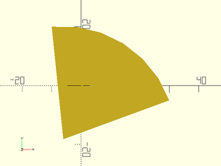
Example 1:
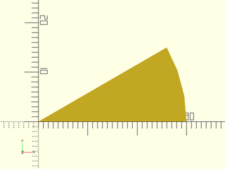
include <BOSL2/std.scad>
arc(n=4, r=30, angle=30, wedge=true);
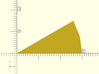
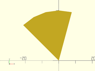
Example 2:

include <BOSL2/std.scad>
arc(r=30, angle=30, wedge=true);
Example 3:
include <BOSL2/std.scad>
arc(d=60, angle=30, wedge=true);
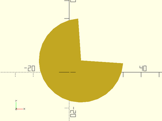
Example 4:
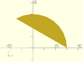
include <BOSL2/std.scad>
arc(d=60, angle=120);
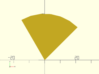
Example 5:
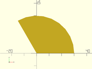
include <BOSL2/std.scad>
arc(d=60, angle=120, wedge=true);
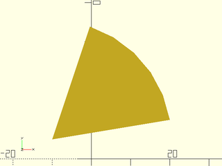
Example 6:
include <BOSL2/std.scad>
arc(r=30, angle=[75,135], wedge=true);
Example 7:
include <BOSL2/std.scad>
arc(r=30, start=45, angle=75, wedge=true);
Example 8:
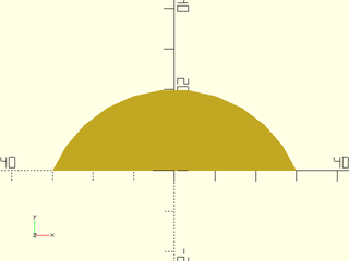
include <BOSL2/std.scad>
arc(width=60, thickness=20);
Example 9:
include <BOSL2/std.scad>
arc(cp=[-10,5], points=[[20,10],[0,35]], wedge=true);
Example 10:
include <BOSL2/std.scad>
arc(points=[[30,-5],[20,10],[-10,20]], wedge=true);
Example 11: Fit to three points.
include <BOSL2/std.scad>
arc(points=[[5,30],[-10,-10],[30,5]], wedge=true);
Example 12:
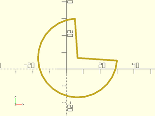
include <BOSL2/std.scad>
path = arc(points=[[5,30],[-10,-10],[30,5]], wedge=true);
stroke(closed=true, path);
Example 13:
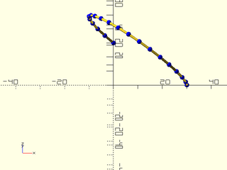
include <BOSL2/std.scad>
path = arc(points=[[0,30,0],[0,0,30],[30,0,0]]);
stroke(path, dots=true, dots_color="blue");
Example 14: Fit to a corner.
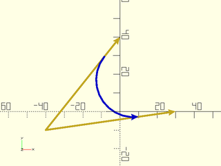
include <BOSL2/std.scad>
pts = [[0,40], [-40,-10], [30,0]];
path = arc(corner=pts, r=20);
stroke(pts, endcaps="arrow2");
stroke(path, endcap2="arrow2", color="blue");
Synopsis: Returns a 2D Catenary chain or arch path. [Path]
Topics: Paths
Usage:
- path = catenary(width, droop=|angle=, n=);
Description:
Returns a 2D Catenary path, which is the path a chain held at both ends will take.
The path will have the endpoints at [±width/2, 0], and the middle of the path will droop
towards Y- if the given droop= or angle= is positive. It will droop towards Y+ if the
droop= or angle= is negative. You must specify one of droop= or angle=.
Arguments:
| By Position | What it does |
|---|---|
width |
The straight-line distance between the endpoints of the path. |
droop |
If given, specifies the height difference between the endpoints and the hanging middle of the path. If given a negative value, returns an arch above the Y axis. |
n |
The number of points to return in the path. Default: 100 |
| By Name | What it does |
|---|---|
angle |
If given, specifies the angle that the path will droop by at the endpoints. If given a negative value, returns an arch above the Y axis. |
anchor |
Translate so anchor point is at origin (0,0,0). See anchor. (Module only) Default: CENTER
|
spin |
Rotate this many degrees around the Z axis after anchor. See spin. (Module only) Default: 0
|
Example 1: By Droop
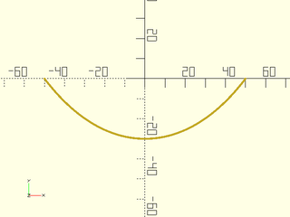
include <BOSL2/std.scad>
stroke(catenary(100, droop=30));
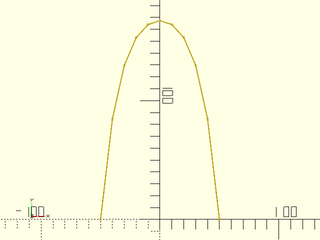
Example 2: By Angle
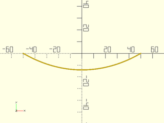
include <BOSL2/std.scad>
stroke(catenary(100, angle=30));
Example 3: Upwards Arch by Angle

include <BOSL2/std.scad>
stroke(catenary(100, angle=30));
Example 4: Upwards Arch by Height Delta
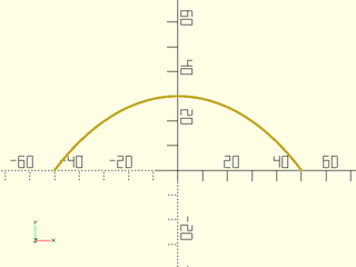
include <BOSL2/std.scad>
stroke(catenary(100, droop=-30));
Example 5: Specifying Vertex Count
include <BOSL2/std.scad>
stroke(catenary(100, angle=-85, n=11), dots="dot");
Example 6: Sweeping a Catenary Path
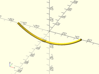
include <BOSL2/std.scad>
path = xrot(90, p=path3d(catenary(100, droop=20, n=41)));
path_sweep(circle(r=1.5, $fn=24), path);
Synopsis: Creates a 2d spiral or 3d helical path. [Path]
Topics: Path Generators, Paths, Drawing Tools
See Also: pie_slice(), stroke(), thread_helix(), path_sweep()
Usage:
- path = helix(l|h, [turns=], [angle=], r=|r1=|r2=, d=|d1=|d2=);
Description:
Returns a 3D helical path on a cone, including the degerate case of flat spirals. You can specify start and end radii. You can give the length, the helix angle, or the number of turns: two of these three parameters define the helix. For a flat helix you must give length 0 and a turn count. Helix will be right handed if turns is positive and left handed if it is negative. The angle is calculateld based on the radius at the base of the helix.
Arguments:
| By Position | What it does |
|---|---|
h / l
|
Height/length of helix, zero for a flat spiral |
| By Name | What it does |
|---|---|
turns |
Number of turns in helix, positive for right handed |
angle |
helix angle |
r |
Radius of helix |
r1 |
Radius of bottom of helix |
r2 |
Radius of top of helix |
d |
Diameter of helix |
d1 |
Diameter of bottom of helix |
d2 |
Diameter of top of helix |
Example 1:
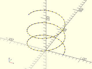
include <BOSL2/std.scad>
stroke(helix(turns=2.5, h=100, r=50), dots=true, dots_color="blue");
Example 2: Helix that turns the other way
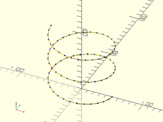
include <BOSL2/std.scad>
stroke(helix(turns=-2.5, h=100, r=50), dots=true, dots_color="blue");
Example 3: Flat helix (note points are still 3d)
include <BOSL2/std.scad>
stroke(helix(h=0,r1=50,r2=25,l=0, turns=4));
Synopsis: Uses turtle graphics to generate a 2D path. [Path]
Topics: Shapes (2D), Path Generators (2D), Mini-Language
See Also: turtle3d(), stroke(), path_sweep()
Usage:
- path = turtle(commands, [state], [full_state=], [repeat=])
Description:
Use a sequence of [turtle graphics]{https://en.wikipedia.org/wiki/Turtle_graphics} commands to generate a path. The parameter commands is a list of
turtle commands and optional parameters for each command. The turtle state has a position, movement direction,
movement distance, and default turn angle. If you do not give state as input then the turtle starts at the
origin, pointed along the positive x axis with a movement distance of 1. By default, turtle returns just
the computed turtle path. If you set full_state to true then it instead returns the full turtle state.
You can invoke turtle again with this full state to continue the turtle path where you left off.
The turtle state is a list with three entries: the path constructed so far, the current step as a 2-vector, the current default angle, and the current arcsteps setting.
| Commands | Arguments | What it does |
|---|---|---|
| "move" | [dist] | Move turtle scale*dist units in the turtle direction. Default dist=1. |
| "xmove" | [dist] | Move turtle scale*dist units in the x direction. Default dist=1. Does not change turtle direction. |
| "ymove" | [dist] | Move turtle scale*dist units in the y direction. Default dist=1. Does not change turtle direction. |
| "xymove" | vector | Move turtle by the specified vector. Does not change turtle direction. |
| "untilx" | xtarget | Move turtle in turtle direction until x==xtarget. Produces an error if xtarget is not reachable. |
| "untily" | ytarget | Move turtle in turtle direction until y==ytarget. Produces an error if ytarget is not reachable. |
| "jump" | point | Move the turtle to the specified point |
| "xjump" | x | Move the turtle's x position to the specified value |
| "yjump | y | Move the turtle's y position to the specified value |
| "turn" | [angle] | Turn turtle direction by specified angle, or the turtle's default turn angle. The default angle starts at 90. |
| "left" | [angle] | Same as "turn" |
| "right" | [angle] | Same as "turn", -angle |
| "angle" | angle | Set the default turn angle. |
| "setdir" | dir | Set turtle direction. The parameter dir can be an angle or a vector. |
| "length" | length | Change the turtle move distance to length
|
| "scale" | factor | Multiply turtle move distance by factor
|
| "addlength" | length | Add length to the turtle move distance |
| "repeat" | count, commands | Repeats a list of commands count times. |
| "arcleft" | radius, [angle] | Draw an arc from the current position toward the left at the specified radius and angle. The turtle turns by angle. A negative angle draws the arc to the right instead of the left, and leaves the turtle facing right. A negative radius draws the arc to the right but leaves the turtle facing left. |
| "arcright" | radius, [angle] | Draw an arc from the current position toward the right at the specified radius and angle |
| "arcleftto" | radius, angle | Draw an arc at the given radius turning toward the left until reaching the specified absolute angle. |
| "arcrightto" | radius, angle | Draw an arc at the given radius turning toward the right until reaching the specified absolute angle. |
| "arcsteps" | count | Specifies the number of segments to use for drawing arcs. If you set it to zero then the standard $fn, $fa and $fs variables define the number of segments. |
Arguments:
| By Position | What it does |
|---|---|
commands |
List of turtle commands |
state |
Starting turtle state (from previous call) or starting point. Default: start at the origin, pointing right. |
| By Name | What it does |
|---|---|
full_state |
If true return the full turtle state for continuing the path in subsequent turtle calls. Default: false |
repeat |
Number of times to repeat the command list. Default: 1 |
Example 1: Simple rectangle
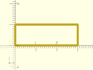
include <BOSL2/std.scad>
path = turtle(["xmove",3, "ymove", "xmove",-3, "ymove",-1]);
stroke(path,width=.1);
Example 2: Pentagon
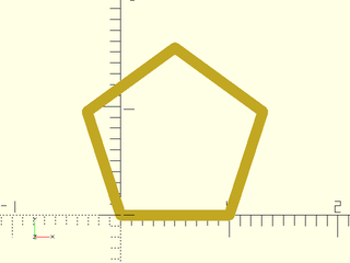
include <BOSL2/std.scad>
path=turtle(["angle",360/5,"move","turn","move","turn","move","turn","move"]);
stroke(path,width=.1,closed=true);
Example 3: Pentagon using the repeat argument

include <BOSL2/std.scad>
path=turtle(["move","turn",360/5],repeat=5);
stroke(path,width=.1,closed=true);
Example 4: Pentagon using the repeat turtle command, setting the turn angle

include <BOSL2/std.scad>
path=turtle(["angle",360/5,"repeat",5,["move","turn"]]);
stroke(path,width=.1,closed=true);
Example 5: Pentagram
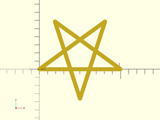
include <BOSL2/std.scad>
path = turtle(["move","left",144], repeat=4);
stroke(path,width=.05,closed=true);
Example 6: Sawtooth path
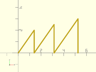
include <BOSL2/std.scad>
path = turtle([
    "turn", 55,
    "untily", 2,
    "turn", -55-90,
    "untily", 0,
    "turn", 55+90,
    "untily", 2.5,
    "turn", -55-90,
    "untily", 0,
    "turn", 55+90,
    "untily", 3,
    "turn", -55-90,
    "untily", 0
]);
stroke(path, width=.1);
Example 7: Simpler way to draw the sawtooth. The direction of the turtle is preserved when executing "yjump".

include <BOSL2/std.scad>
path = turtle([
    "turn", 55,
    "untily", 2,
    "yjump", 0,
    "untily", 2.5,
    "yjump", 0,
    "untily", 3,
    "yjump", 0,
]);
stroke(path, width=.1);
Example 8: square spiral
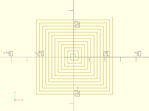
include <BOSL2/std.scad>
path = turtle(["move","left","addlength",1],repeat=50);
stroke(path,width=.2);
Example 9: pentagonal spiral
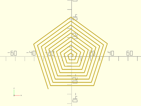
include <BOSL2/std.scad>
path = turtle(["move","left",360/5,"addlength",1],repeat=50);
stroke(path,width=.7);
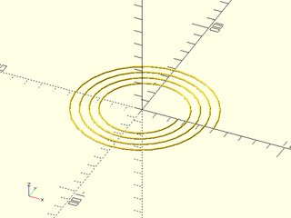
Example 10: yet another spiral, without using repeat
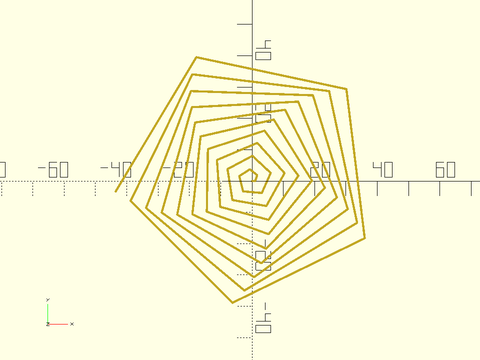
include <BOSL2/std.scad>
path = turtle(concat(["angle",71],flatten(repeat(["move","left","addlength",1],50))));
stroke(path,width=.7);
Example 11: The previous spiral grows linearly and eventually intersects itself. This one grows geometrically and does not.
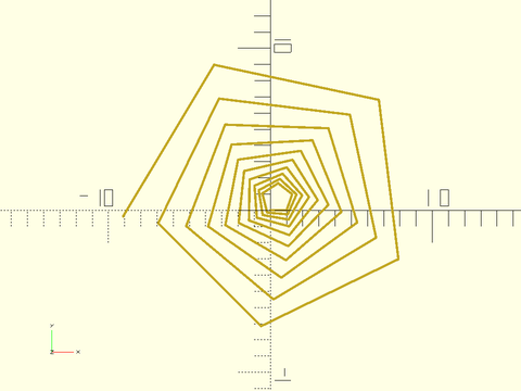
include <BOSL2/std.scad>
path = turtle(["move","left",71,"scale",1.05],repeat=50);
stroke(path,width=.15);
Example 12: Koch Snowflake
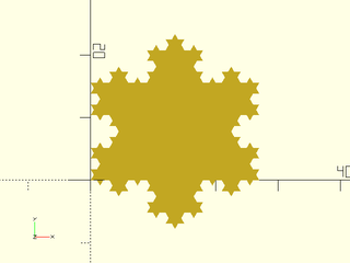
include <BOSL2/std.scad>
function koch_unit(depth) =
    depth==0 ? ["move"] :
    concat(
        koch_unit(depth-1),
        ["right"],
        koch_unit(depth-1),
        ["left","left"],
        koch_unit(depth-1),
        ["right"],
        koch_unit(depth-1)
    );
koch=concat(["angle",60,"repeat",3],[concat(koch_unit(3),["left","left"])]);
polygon(turtle(koch));
Synopsis: Draws an annotated polygon. [Geom]
Topics: Shapes (2D)
See Also: debug_region(), debug_vnf(), debug_bezier()
Usage:
- debug_polygon(points, paths, [vertices=], [edges=], [convexity=], [size=]);
Description:
A drop-in replacement for polygon() that renders and labels the path points and
edges. The start of each path is marked with a blue circle and the end with a pink diamond.
You can suppress the display of vertex or edge labeling using the vertices and edges arguments.
Arguments:
| By Position | What it does |
|---|---|
points |
The array of 2D polygon vertices. |
paths |
The path connections between the vertices. |
| By Name | What it does |
|---|---|
vertices |
if true display vertex labels and start/end markers. Default: true |
edges |
if true display edge labels. Default: true |
convexity |
The max number of walls a ray can pass through the given polygon paths. |
size |
The base size of the line and labels. |
Example 1:
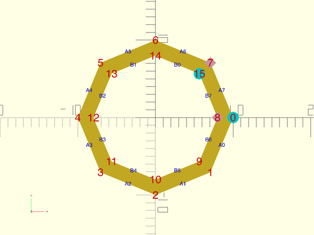
include <BOSL2/std.scad>
debug_polygon(
    points=concat(
        regular_ngon(or=10, n=8),
        regular_ngon(or=8, n=8)
    ),
    paths=[
        [for (i=[0:7]) i],
        [for (i=[15:-1:8]) i]
    ]
);