hinges.scad
Functions and modules for creating hinges and snap-locking hinged parts.
To use, add the following lines to the beginning of your file:
include <BOSL2/std.scad>
include <BOSL2/hinges.scad>
-
-
knuckle_hinge()– Creates a knuckle-hinge shape. [Geom] -
living_hinge_mask()– Creates a mask to make a folding "living" hinge. [Geom]
-
-
-
apply_folding_hinges_and_snaps()– Adds snap shapes and removes living hinges from a child shape. [Geom] -
snap_lock()– Creates a snap-lock shape. [Geom] -
snap_socket()– Creates a snap-lock socket shape. [Geom]
-
Synopsis: Creates a knuckle-hinge shape. [Geom]
See Also: living_hinge_mask(), snap_lock(), snap_socket()
Usage:
- knuckle_hinge(length, offset, segs, [inner], [arm_height=], [arm_angle=], [fill=], [clear_top=], [gap=], [round_top=], [round_bot=], [knuckle_diam=], [pin_diam=], [pin_fn=], [anchor=], [spin=], [orient=]) [ATTACHMENTS];
Description:
Construct standard knuckle hinge in two parts using a hinge pin that must be separately supplied. The default is configured to use a piece of 1.75 mm filament as the hinge pin, but you can select any dimensions you like to use a screw or other available pin material. The BOTTOM of the hinge is its mount point, which is aligned with the hinge pin centersurface, and the hinge pin hole is the CENTER of the hinge. The offset is the distance from a vertical mounting point to the center of the hinge pin. The hinge barrel is held by an angled support and vertical support. The length of the angled support is determined by its angle and the offset. You specify the length of the vertical support with the arm_height parameter.
A hinge requires clearance so its parts don't interfere. If the hinge pin is exactly centered on
the top of your part, then the hinge may not close all the way due to interference at the edge.
A small clearance, specified with clearance=, raises the hinge up and can ease this
interference. It should probably be equal to a layer thickness or two. If the hinge knuckle is
close to the hinged part then the mating part may interfere. You can create clearance to address
this problem by increasing the offset to move the hinge knuckles farther away. Another method is
to cut out a curved recess on the parts to allow space for the other hinges. This is possible
using the knuckle_clearance= parameter, which specifies the extra space to cut away to leave
room for the hinge knuckles. It must be positive for any space to be cut, and to use this option
you must make the hinge a child of some object and specify diff() for the parent object of
the hinge.
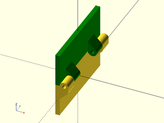
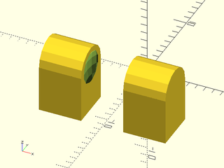
Figure 1: The basic hinge form appears on the left. If fill is set to true the gap between the mount surface and hinge arm is filled as shown on the right.

As shown in the above figure, the fill option fills the gap between the hinge arm and the mount surface to make a stronger connection. When the arm height is set to zero, only a single segment connects the hinge barrel to the mount surface.
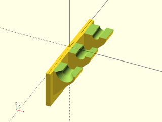
Figure 2: Zero arm height with 45 deg arm

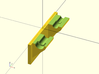
Figure 3: Zero arm height with 90 deg arm. The clear_top parameter removes the hinge support material that is above the x axis

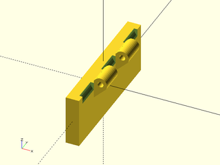
Figure 4: An excessively large clearance value raises up the hinge center. Note that the hinge mounting remains bounded by the X axis, so when fill=true or clear_top=true this is different than simply raising up the entire hinge.

For 3D printability, you may prefer a teardrop shaped hole, which you can get with teardrop=true;
if necessary you can specify the teardrop direction to be UP, DOWN, FORWARD, or BACK.
(These directions assume that the base of the hinge is mounted on the back of something.)
Another option for printability is to use an octagonal hole, though it does seem more
difficult to size these for robust printability. To get an octagonal hole set pin_fn=8.
Figure 5: Alternate hole shapes for improved 3D printabililty

The default pin hole size admits a piece of 1.75 mm filament. If you prefer to use a machine
screw you can set the pin_diam to a screw specification like "M3" or "#6". In this case,
a clearance hole is created through most of the hinge with a self-tap hole for the last segment.
If the last segment is very long you may shrink the self-tap portion using the tap_depth parameter.
The pin hole diameter is enlarged by the 2*$slop for numerically specified holes.
Screw holes are made using screw_hole() which enlarges the hole by 4*$slop.
To blend hinges better with a model you can round off the joint with the mounting surface using
the round_top and round_bot parameters, which specify the cut distance, the amount of material to add.
They make a continuous curvature "smooth" roundover with k=0.8. See smooth roundovers for more
information. If you specify too large of a roundover you will get an error that the rounding doesn't fit.
Figure 6: Top and bottom roundovers for smooth hinge attachment

Arguments:
| By Position | What it does |
|---|---|
length |
total length of the entire hinge |
offset |
horizontal offset of the hinge pin center from the mount point |
segs |
number of hinge segments |
inner |
set to true for the "inner" hinge. Default: false |
| By Name | What it does |
|---|---|
arm_height |
vertical height of the arm that holds the hinge barrel. Default: 0 |
arm_angle |
angle of the arm down from the vertical. Default: 45 |
fill |
if true fill in space between arm and mount surface. Default: true |
clear_top |
if true remove any excess arm geometry that appears above the top of the mount surface. Default: false |
gap |
gap between hinge segments. Default: 0.2 |
round_top |
rounding amount to add where top of hinge arm joins the mount surface. Generally only useful when fill=false. Default: 0 |
round_bot |
rounding amount to add where bottom of hinge arm joins the mount surface. Default: 0 |
knuckle_diam |
diameter of hinge barrel. Default: 4 |
pin_diam |
diameter of hinge pin hole as a number of screw specification. Default: 1.75 |
pin_fn |
$fn value to use for the pin. |
teardrop |
Set to true or UP/DOWN/FWD/BACK to specify teardrop shape for the pin hole. Default: false |
screw_head |
screw head to use for countersink |
screw_tolerance |
screw hole tolerance. Default: "close" |
tap_depth |
Don't make the tapped part of the screw hole larger than this. |
$slop |
increases pin hole diameter |
clearance |
raises pin hole to create clearance at the edge of the mounted surface. Default: 0.15 |
clear_knuckle |
clear space for hinge knuckle of mating part. Must use with diff(). Default: 0 |
anchor |
Translate so anchor point is at origin (0,0,0). See anchor. Default: BOTTOM
|
spin |
Rotate this many degrees around the Z axis after anchor. See spin. Default: 0
|
orient |
Vector to rotate top towards, after spin. See orient. Default: UP
|
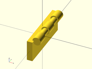
Example 1: Basic hinge, inner=false in front and inner=true in the back
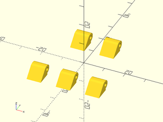
include <BOSL2/std.scad>
include <BOSL2/hinges.scad>
$fn=32;
ydistribute(30){
  knuckle_hinge(length=35, segs=5, offset=3, arm_height=1);
  knuckle_hinge(length=35, segs=5, offset=3, arm_height=1,inner=true);
}
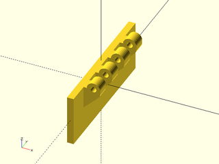
Example 2: Basic hinge, mounted. Odd segment count means the "outside" hinge is on the outside at both ends.

include <BOSL2/std.scad>
include <BOSL2/hinges.scad>
$fn=32;
cuboid([2,40,15])
  position(TOP+RIGHT) orient(anchor=RIGHT)
    knuckle_hinge(length=35, segs=9, offset=3, arm_height=1);
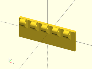
Example 3: Corresponding inner hinge to go with previous example. Note that the total number of hinge segments adds to the 9 specified.
include <BOSL2/std.scad>
include <BOSL2/hinges.scad>
$fn=32;
cuboid([2,40,15])
  position(TOP+RIGHT) orient(anchor=RIGHT)
    knuckle_hinge(length=35, segs=9, offset=3, arm_height=1, inner=true);
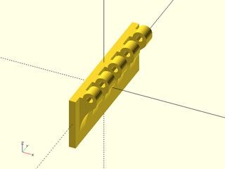
Example 4: This example shows how to position and orient the hinge onto the front of an object instead of the right side.
include <BOSL2/std.scad>
include <BOSL2/hinges.scad>
$fn=32;
cuboid([40,2,15])
  position(TOP+FRONT) orient(anchor=FWD)
    knuckle_hinge(length=35, segs=9, offset=3, arm_height=1);
Example 5: Hinge with round_bot set to create a smooth transition, but octagonal hinge pin holes for printing
include <BOSL2/std.scad>
include <BOSL2/hinges.scad>
$fn=32;
cuboid([2,40,15])
  position(TOP+RIGHT) orient(anchor=RIGHT)
    knuckle_hinge(length=35, segs=9, offset=3, arm_height=1,
          round_bot=1, pin_fn=8);
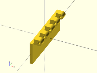
Example 6: Hinge with no vertical arm, just angled arm
include <BOSL2/std.scad>
include <BOSL2/hinges.scad>
$fn=32;
cuboid([2,40,15])
  position(TOP+RIGHT) orient(anchor=RIGHT)
    knuckle_hinge(length=35, segs=9, offset=3, pin_fn=8);
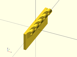
Example 7: Setting the arm_angle to a large value like 90 produces a hinge that doesn't look great
include <BOSL2/std.scad>
include <BOSL2/hinges.scad>
$fn=32;
cuboid([2,40,15])
  position(TOP+RIGHT) orient(anchor=RIGHT)
    knuckle_hinge(length=35, segs=9, offset=3, arm_angle=90,
          arm_height=0, pin_fn=8);
Example 8: The above hinge is improved with clear_top, which allows nice attachment to a shape half the thickness of the hinge barrel
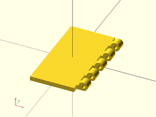
include <BOSL2/std.scad>
include <BOSL2/hinges.scad>
$fn=32;
cuboid([20,40,2])
  position(TOP+RIGHT) orient(anchor=RIGHT)
    knuckle_hinge(length=35, segs=9, offset=3, arm_height=0,
          arm_angle=90, pin_fn=8, clear_top=true);
Example 9: Uneven hinge using seg_ratio. Here the inner hinge segments are 1/3 the outer, a rather extreme difference. Note also that it's a little simpler to mount the inner hinge on the LEFT side of the top section to interface with the hinge mounted on the RIGHT.
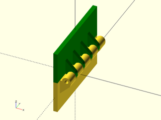
include <BOSL2/std.scad>
include <BOSL2/hinges.scad>
$fn=32;
cuboid([2,40,15]){
  position(TOP+RIGHT) orient(anchor=RIGHT)
    knuckle_hinge(length=35, segs=9, offset=3, arm_height=1,
          seg_ratio=1/3);
  attach(TOP,TOP) color("green")
    cuboid([2,40,15],anchor=TOP)
      position(TOP+LEFT) orient(anchor=LEFT)
        knuckle_hinge(length=35, segs=9, offset=3, arm_height=1,
              seg_ratio=1/3, inner=true);
 }
Example 10: A single hinge with an even number of segments will probably look strange, but they work together neatly in a pair. This example also shows that the arm_height can change between the inner and outer hinge parts and they will still interface properly.
include <BOSL2/std.scad>
include <BOSL2/hinges.scad>
$fn=32;
cuboid([2,40,15]){
  yflip_copy()
    position(TOP+RIGHT+FRONT) orient(anchor=RIGHT)
      knuckle_hinge(length=12, segs=2, offset=2, arm_height=2,
            anchor=BOT+LEFT);
  attach(TOP,TOP) color("green")
    cuboid([2,40,15],anchor=TOP)
      yflip_copy()
        position(TOP+LEFT+FRONT) orient(anchor=LEFT)
          knuckle_hinge(length=12, segs=2, offset=2, arm_height=0,
                inner=true, anchor=BOT+RIGHT);
 }
Example 11: Hinge with self-tapping screw hole. Note that last segment has smaller diameter for screw to bite, whereas other segments have clearance holes.
include <BOSL2/std.scad>
include <BOSL2/hinges.scad>
$fn=32;
bottom_half(z=.01)
  cuboid([2,40,15],anchor=TOP)
    position(TOP+RIGHT) orient(anchor=RIGHT)
      knuckle_hinge(length=35, segs=5, offset=5, knuckle_diam=9, pin_diam="#6", fill=false,inner=false, screw_head="flat");
Example 12: If you give a non-flat screw head then a counterbore for that head is generated. If you don't want the counterbore, don't give a head type. In this example, tap_depth limits the narrower self-tap section of the hole.
include <BOSL2/std.scad>
include <BOSL2/hinges.scad>
$fn=32;
bottom_half(z=.01)
   cuboid([2,40,15],anchor=TOP)
     position(TOP+RIGHT) orient(anchor=RIGHT)
        knuckle_hinge(length=35, segs=3, offset=5, knuckle_diam=9, pin_diam="#6",
              fill=false, inner=false, tap_depth=6, screw_head="socket");
Example 13: This hinge has a small offset, so the hinged parts may interfere. To prevent this, use knuckle_clearance. This example shows an excessive clearance value to make the effect obvious. Note that you must use diff() when you set knuckle_clearance, and the hinge must be a child of the object it mounts to. Otherwise the cylinders that are supposed to be subtracted will appear as extra objects. This is an inner hinge, so it has clearance zones for the larger outer hinge that will mate with it.
include <BOSL2/std.scad>
include <BOSL2/hinges.scad>
$fn=32;
diff()
  cuboid([4,40,15])
    position(TOP+RIGHT) orient(anchor=RIGHT)
      knuckle_hinge(length=35, segs=5, offset=2, inner=true, knuckle_clearance=1);
Example 14: Oh no! Forgot to use diff() with knuckle_clearance!
include <BOSL2/std.scad>
include <BOSL2/hinges.scad>
$fn=32;
  cuboid([4,40,15])
    position(TOP+RIGHT) orient(anchor=RIGHT)
      knuckle_hinge(length=35, segs=5, offset=2, inner=true, knuckle_clearance=1);
Synopsis: Creates a mask to make a folding "living" hinge. [Geom]
See Also: knuckle_hinge(), snap_lock(), snap_socket(), apply_folding_hinges_and_snaps()
Usage:
- living_hinge_mask(l, thick, [layerheight=], [foldangle=], [hingegap=], [$slop=], [anchor=], [spin=], [orient=]) [ATTACHMENTS];
Description:
Creates a mask to be differenced away from a plate to create a "live" hinge, where a thin layer of plastic holds two parts together.
Center the mask at the bottom of the part you want to make a hinge in.
The mask will leave hinge material 2*layerheight thick on the bottom of the hinge.
Arguments:
| By Position | What it does |
|---|---|
l |
Length of the hinge in mm. |
thick |
Thickness in mm of the material to make the hinge in. |
| By Name | What it does |
|---|---|
layerheight |
The expected printing layer height in mm. |
foldangle |
The interior angle in degrees of the joint to be created with the hinge. Default: 90 |
hingegap |
Size in mm of the gap at the bottom of the hinge, to make room for folding. |
$slop |
Increase size of hinge gap by double this amount |
anchor |
Translate so anchor point is at origin (0,0,0). See anchor. Default: CENTER
|
spin |
Rotate this many degrees around the Z axis. See spin. Default: 0
|
orient |
Vector to rotate top towards. See orient. Default: UP
|
Example 1:
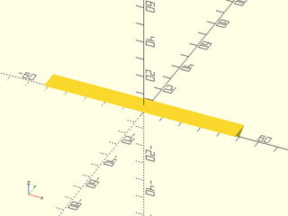
include <BOSL2/std.scad>
include <BOSL2/hinges.scad>
living_hinge_mask(l=100, thick=3, foldangle=60);
Synopsis: Adds snap shapes and removes living hinges from a child shape. [Geom]
See Also: knuckle_hinge(), living_hinge_mask(), snap_lock(), snap_socket()
Usage:
- apply_folding_hinges_and_snaps(thick, [foldangle=], [hinges=], [snaps=], [sockets=], [snaplen=], [snapdiam=], [hingegap=], [layerheight=], [$slop=]) CHILDREN;
Description:
Adds snaplocks and create hinges in children at the given positions.
Arguments:
| By Position | What it does |
|---|---|
thick |
Thickness in mm of the material to make the hinge in. |
foldangle |
The interior angle in degrees of the joint to be created with the hinge. Default: 90 |
hinges |
List of [LENGTH, POSITION, SPIN] for each hinge to difference from the children. |
snaps |
List of [POSITION, SPIN] for each central snaplock to add to the children. |
sockets |
List of [POSITION, SPIN] for each outer snaplock sockets to add to the children. |
snaplen |
Length of locking snaps. |
snapdiam |
Diameter/width of locking snaps. |
hingegap |
Size in mm of the gap at the bottom of the hinge, to make room for folding. |
layerheight |
The expected printing layer height in mm. |
| By Name | What it does |
|---|---|
$slop |
increase hinge gap by twice this amount |
Example 1:
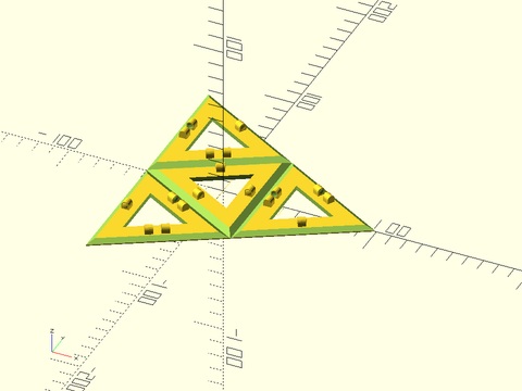
include <BOSL2/std.scad>
include <BOSL2/hinges.scad>
size=100;
apply_folding_hinges_and_snaps(
    thick=3, foldangle=acos(1/3),
    hinges=[
        for (a=[0,120,240], b=[-size/2,size/4]) each [
            [200, polar_to_xy(b,a), a+90]
        ]
    ],
    snaps=[
        for (a=[0,120,240]) each [
            [rot(a,p=[ size/4, 0        ]), a+90],
            [rot(a,p=[-size/2,-size/2.33]), a-90]
        ]
    ],
    sockets=[
        for (a=[0,120,240]) each [
            [rot(a,p=[ size/4, 0        ]), a+90],
            [rot(a,p=[-size/2, size/2.33]), a+90]
        ]
    ]
) {
    $fn=3;
    difference() {
        cylinder(r=size-1, h=3);
        down(0.01) cylinder(r=size/4.5, h=3.1, spin=180);
        down(0.01) for (a=[0:120:359.9]) zrot(a) right(size/2) cylinder(r=size/4.5, h=3.1);
    }
}
Synopsis: Creates a snap-lock shape. [Geom]
See Also: knuckle_hinge(), living_hinge_mask(), snap_socket()
Usage:
- snap_lock(thick, [snaplen=], [snapdiam=], [layerheight=], [foldangle=], [hingegap=], [$slop=], [anchor=], [spin=], [orient=]) [ATTACHMENTS];
Description:
Creates the central snaplock part.
Arguments:
| By Position | What it does |
|---|---|
thick |
Thickness in mm of the material to make the hinge in. |
| By Name | What it does |
|---|---|
snaplen |
Length of locking snaps. |
snapdiam |
Diameter/width of locking snaps. |
layerheight |
The expected printing layer height in mm. |
foldangle |
The interior angle in degrees of the joint to be created with the hinge. Default: 90 |
hingegap |
Size in mm of the gap at the bottom of the hinge, to make room for folding. |
$slop |
increase size of hinge gap by double this amount |
anchor |
Translate so anchor point is at origin (0,0,0). See anchor. Default: CENTER
|
spin |
Rotate this many degrees around the Z axis. See spin. Default: 0
|
orient |
Vector to rotate top towards. See orient. Default: UP
|
Example 1:
include <BOSL2/std.scad>
include <BOSL2/hinges.scad>
snap_lock(thick=3, foldangle=60);
Synopsis: Creates a snap-lock socket shape. [Geom]
See Also: knuckle_hinge(), living_hinge_mask(), snap_lock()
Usage:
- snap_socket(thick, [snaplen=], [snapdiam=], [layerheight=], [foldangle=], [hingegap=], [$slop=], [anchor=], [spin=], [orient=]) [ATTACHMENTS];
Description:
Creates the outside snaplock socketed part.
Arguments:
| By Position | What it does |
|---|---|
thick |
Thickness in mm of the material to make the hinge in. |
| By Name | What it does |
|---|---|
snaplen |
Length of locking snaps. |
snapdiam |
Diameter/width of locking snaps. |
layerheight |
The expected printing layer height in mm. |
foldangle |
The interior angle in degrees of the joint to be created with the hinge. Default: 90 |
hingegap |
Size in mm of the gap at the bottom of the hinge, to make room for folding. |
$slop |
Increase size of hinge gap by double this amount |
anchor |
Translate so anchor point is at origin (0,0,0). See anchor. Default: CENTER
|
spin |
Rotate this many degrees around the Z axis. See spin. Default: 0
|
orient |
Vector to rotate top towards. See orient. Default: UP
|
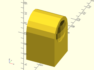
Example 1:
include <BOSL2/std.scad>
include <BOSL2/hinges.scad>
snap_socket(thick=3, foldangle=60);