shapes3d.scad
Some standard modules for making 3d shapes with attachment support, and function forms that produce a VNF. Also included are shortcuts cylinders in each orientation and extended versions of the standard modules that provide roundovers and chamfers. The spheroid() module provides several different ways to make a sphere, and the text modules let you write text on a path so you can place it on a curved object. A ruler lets you measure objects.
To use, add the following lines to the beginning of your file:
include <BOSL2/std.scad>
-
Section: Cuboids, Prismoids and Pyramids
-
cube()– Creates a cube with anchors for attaching children. [Geom] [VNF] [Ext] -
cuboid()– Creates a cube with chamfering and roundovers. [Geom] -
prismoid()– Creates a rectangular prismoid shape with optional roundovers and chamfering. [Geom] [VNF] -
octahedron()– Creates an octahedron with axis-aligned points. [Geom] [VNF] -
rect_tube()– Creates a rectangular tube. [Geom] -
wedge()– Creates a 3d triangular wedge. [Geom] [VNF]
-
-
-
cylinder()– Creates an attachable cylinder. [Geom] [VNF] [Ext] -
cyl()– Creates an attachable cylinder with roundovers and chamfering. [Geom] [VNF] -
xcyl()– creates a cylinder oriented along the X axis. [Geom] -
ycyl()– Creates a cylinder oriented along the y axis. [Geom] -
zcyl()– Creates a cylinder oriented along the Z axis. [Geom] -
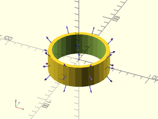
tube()– Creates a cylindrical or conical tube. [Geom] -
pie_slice()– Creates a pie slice shape. [Geom] [VNF]
-
-
-
sphere()– Creates an attachable spherical object. [Geom] [VNF] [Ext] -
spheroid()– Creates an attachable spherical object with controllable triangulation. [Geom] [VNF] -
torus()– Creates an attachable torus. [Geom] [VNF] -
teardrop()– Creates a teardrop shape. [Geom] [VNF] -
onion()– Creates an attachable onion-like shape. [Geom] [VNF]
-
-
-
text3d()– Creates an attachable 3d text block. [Geom] -
path_text()– Creates 2d or 3d text placed along a path. [Geom]
-
-
-
fillet()– Creates a smooth fillet between two faces. [Geom] [VNF] -
heightfield()– Generates a 3D surface from a 2D grid of values. [Geom] [VNF] -
cylindrical_heightfield()– Generates a cylindrical 3d surface from a 2D grid of values. [Geom] [VNF] -
ruler()– Creates a ruler. [Geom]
-
Synopsis: Creates a cube with anchors for attaching children. [Geom] [VNF] [Ext]
Topics: Shapes (3D), Attachable, VNF Generators
See Also: cuboid(), prismoid()
Usage: As Module (as in native OpenSCAD)
- cube(size, [center]);
Usage: With BOSL2 Attachment extensions
- cube(size, [center], [anchor=], [spin=], [orient=]) [ATTACHMENTS];
Usage: As Function (BOSL2 extension)
- vnf = cube(size, ...);
Description:
Creates a 3D cubic object. This module extends the built-in cube()` module by providing support for attachments and a function form. When called as a function, returns a VNF for a cube.
Arguments:
| By Position | What it does |
|---|---|
size |
The size of the cube. |
center |
If given, overrides anchor. A true value sets anchor=CENTER, false sets anchor=FRONT+LEFT+BOTTOM. |
| By Name | What it does |
|---|---|
anchor |
Translate so anchor point is at origin (0,0,0). See anchor. Default: CENTER
|
spin |
Rotate this many degrees around the Z axis after anchor. See spin. Default: 0
|
orient |
Vector to rotate top towards, after spin. See orient. Default: UP
|
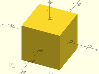
Example 1: Simple cube.
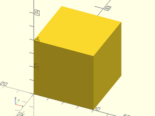
include <BOSL2/std.scad>
cube(40);
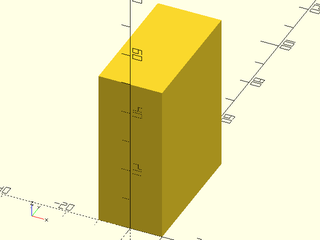
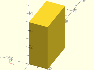
Example 2: Rectangular cube.

include <BOSL2/std.scad>
cube([20,40,50]);
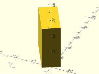
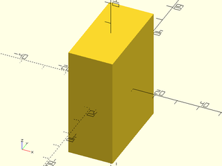
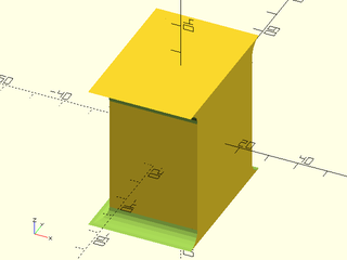
Example 3: Anchoring.
include <BOSL2/std.scad>
cube([20,40,50], anchor=BOTTOM+FRONT);
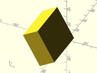
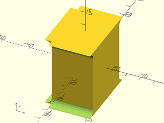
Example 4: Spin.
include <BOSL2/std.scad>
cube([20,40,50], anchor=BOTTOM+FRONT, spin=30);
Example 5: Orientation.
include <BOSL2/std.scad>
cube([20,40,50], anchor=BOTTOM+FRONT, spin=30, orient=FWD);
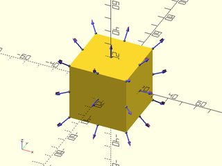
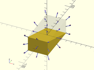
Example 6: Standard Connectors.

include <BOSL2/std.scad>
cube(40, center=true) show_anchors();
Example 7: Called as Function
include <BOSL2/std.scad>
vnf = cube([20,40,50]);
vnf_polyhedron(vnf);
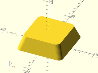
Synopsis: Creates a cube with chamfering and roundovers. [Geom]
Topics: Shapes (3D), Attachable, VNF Generators
See Also: prismoid(), rounded_prism()
Usage: Standard Cubes
- cuboid(size, [anchor=], [spin=], [orient=]);
- cuboid(size, p1=, ...);
- cuboid(p1=, p2=, ...);
Usage: Chamfered Cubes
- cuboid(size, [chamfer=], [edges=], [except=], [trimcorners=], ...);
Usage: Rounded Cubes
- cuboid(size, [rounding=], [teardrop=], [edges=], [except=], [trimcorners=], ...);
Usage: Attaching children
- cuboid(...) ATTACHMENTS;
Description:
Creates a cube or cuboid object, with optional chamfering or rounding of edges and corners. You cannot mix chamfering and rounding: just one edge treatment with the same size applies to all selected edges. Negative chamfers and roundings can be applied to create external fillets, but they only apply to edges around the top or bottom faces. If you specify an edge set other than "ALL" with negative roundings or chamfers then you will get an error. See Specifying Edges for information on how to specify edge sets.
Arguments:
| By Position | What it does |
|---|---|
size |
The size of the cube, a number or length 3 vector. |
| By Name | What it does |
|---|---|
chamfer |
Size of chamfer, inset from sides. Default: No chamfering. |
rounding |
Radius of the edge rounding. Default: No rounding. |
edges |
Edges to mask. See Specifying Edges. Default: all edges. |
except |
Edges to explicitly NOT mask. See Specifying Edges. Default: No edges. |
trimcorners |
If true, rounds or chamfers corners where three chamfered/rounded edges meet. Default: true
|
teardrop |
If given as a number, rounding around the bottom edge of the cuboid won't exceed this many degrees from vertical. If true, the limit angle is 45 degrees. Default: false
|
p1 |
Align the cuboid's corner at p1, if given. Forces anchor=FRONT+LEFT+BOTTOM. |
p2 |
If given with p1, defines the cornerpoints of the cuboid. |
anchor |
Translate so anchor point is at origin (0,0,0). See anchor. Default: CENTER
|
spin |
Rotate this many degrees around the Z axis. See spin. Default: 0
|
orient |
Vector to rotate top towards. See orient. Default: UP
|
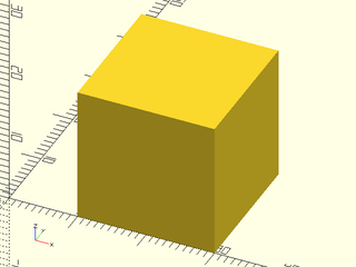
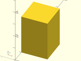
Example 1: Simple regular cube.
include <BOSL2/std.scad>
cuboid(40);
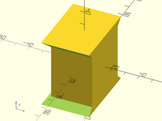
Example 2: Cube with minimum cornerpoint given.
include <BOSL2/std.scad>
cuboid(20, p1=[10,0,0]);
Example 3: Rectangular cube, with given X, Y, and Z sizes.
include <BOSL2/std.scad>
cuboid([20,40,50]);
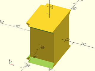
Example 4: Cube by Opposing Corners.
include <BOSL2/std.scad>
cuboid(p1=[0,10,0], p2=[20,30,30]);
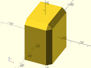
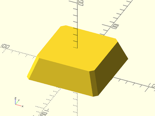
Example 5: Chamferred Edges and Corners.
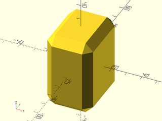
include <BOSL2/std.scad>
cuboid([30,40,50], chamfer=5);
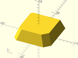
Example 6: Chamferred Edges, Untrimmed Corners.

include <BOSL2/std.scad>
cuboid([30,40,50], chamfer=5, trimcorners=false);
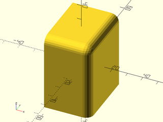
Example 7: Rounded Edges and Corners
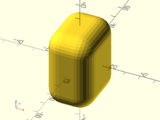
include <BOSL2/std.scad>
cuboid([30,40,50], rounding=10);
Example 8: Rounded Edges and Corners with Teardrop Bottoms
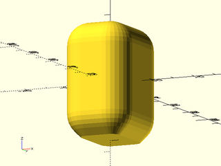
include <BOSL2/std.scad>
cuboid([30,40,50], rounding=10, teardrop=true);
Example 9: Rounded Edges, Untrimmed Corners

include <BOSL2/std.scad>
cuboid([30,40,50], rounding=10, trimcorners=false);
Example 10: Chamferring Selected Edges
include <BOSL2/std.scad>
cuboid(
    [30,40,50], chamfer=5,
    edges=[TOP+FRONT,TOP+RIGHT,FRONT+RIGHT],
    $fn=24
);
Example 11: Rounding Selected Edges
include <BOSL2/std.scad>
cuboid(
    [30,40,50], rounding=5,
    edges=[TOP+FRONT,TOP+RIGHT,FRONT+RIGHT],
    $fn=24
);
Example 12: Negative Chamferring
include <BOSL2/std.scad>
cuboid(
    [30,40,50], chamfer=-5,
    edges=[TOP,BOT], except=RIGHT,
    $fn=24
);
Example 13: Negative Chamferring, Untrimmed Corners
include <BOSL2/std.scad>
cuboid(
    [30,40,50], chamfer=-5,
    edges=[TOP,BOT], except=RIGHT,
    trimcorners=false, $fn=24
);
Example 14: Negative Rounding
include <BOSL2/std.scad>
cuboid(
    [30,40,50], rounding=-5,
    edges=[TOP,BOT], except=RIGHT,
    $fn=24
);
Example 15: Negative Rounding, Untrimmed Corners
include <BOSL2/std.scad>
cuboid(
    [30,40,50], rounding=-5,
    edges=[TOP,BOT], except=RIGHT,
    trimcorners=false, $fn=24
);
Example 16: Roundings and Chamfers can be as large as the full size of the cuboid, so long as the edges would not interfere.
include <BOSL2/std.scad>
cuboid([40,20,10], rounding=20, edges=[FWD+RIGHT,BACK+LEFT]);
Example 17: Standard Connectors
include <BOSL2/std.scad>
cuboid(40) show_anchors();
Synopsis: Creates a rectangular prismoid shape with optional roundovers and chamfering. [Geom] [VNF]
Topics: Shapes (3D), Attachable, VNF Generators
See Also: cuboid(), rounded_prism(), trapezoid(), edge_profile()
Usage:
- prismoid(size1, size2, [h|l|height|length], [shift], [xang=], [yang=], ...) [ATTACHMENTS];
Usage: Chamfered and/or Rounded Prismoids
- prismoid(size1, size2, h|l|height|length, [chamfer=], [rounding=]...) [ATTACHMENTS];
- prismoid(size1, size2, h|l|height|length, [chamfer1=], [chamfer2=], [rounding1=], [rounding2=], ...) [ATTACHMENTS];
Usage: As Function
- vnf = prismoid(...);
Description:
Creates a rectangular prismoid shape with optional roundovers and chamfering.
You can only round or chamfer the vertical(ish) edges. For those edges, you can
specify rounding and/or chamferring per-edge, and for top and bottom separately.
If you want to round the bottom or top edges see rounded_prism().
Specification of the prismoid is similar to specification for trapezoid(). You can specify the dimensions of the
bottom and top and its height to get a symmetric prismoid. You can use the shift argument to shift the top face around.
You can also specify base angles either in the X direction, Y direction or both. In order to avoid overspecification,
you may need to specify a parameter such as size2 as a list of two values, one of which is undef. For example,
specifying size2=[100,undef] sets the size in the X direction but allows the size in the Y direction to be computed based on yang.
Arguments:
| By Position | What it does |
|---|---|
size1 |
[width, length] of the bottom end of the prism. |
size2 |
[width, length] of the top end of the prism. |
h / l / height / length
|
Height of the prism. |
shift |
[X,Y] amount to shift the center of the top end with respect to the center of the bottom end. |
| By Name | What it does |
|---|---|
xang |
base angle in the X direction. Can be a scalar or list of two values, one of which may be undef |
yang |
base angle in the Y direction. Can be a scalar or list of two values, one of which may be undef |
rounding |
The roundover radius for the vertical-ish edges of the prismoid. If given as a list of four numbers, gives individual radii for each corner, in the order [X+Y+,X-Y+,X-Y-,X+Y-]. Default: 0 (no rounding) |
rounding1 |
The roundover radius for the bottom of the vertical-ish edges of the prismoid. If given as a list of four numbers, gives individual radii for each corner, in the order [X+Y+,X-Y+,X-Y-,X+Y-]. |
rounding2 |
The roundover radius for the top of the vertical-ish edges of the prismoid. If given as a list of four numbers, gives individual radii for each corner, in the order [X+Y+,X-Y+,X-Y-,X+Y-]. |
chamfer |
The chamfer size for the vertical-ish edges of the prismoid. If given as a list of four numbers, gives individual chamfers for each corner, in the order [X+Y+,X-Y+,X-Y-,X+Y-]. Default: 0 (no chamfer) |
chamfer1 |
The chamfer size for the bottom of the vertical-ish edges of the prismoid. If given as a list of four numbers, gives individual chamfers for each corner, in the order [X+Y+,X-Y+,X-Y-,X+Y-]. |
chamfer2 |
The chamfer size for the top of the vertical-ish edges of the prismoid. If given as a list of four numbers, gives individual chamfers for each corner, in the order [X+Y+,X-Y+,X-Y-,X+Y-]. |
anchor |
Translate so anchor point is at origin (0,0,0). See anchor. Default: BOTTOM
|
spin |
Rotate this many degrees around the Z axis after anchor. See spin. Default: 0
|
orient |
Vector to rotate top towards, after spin. See orient. Default: UP
|
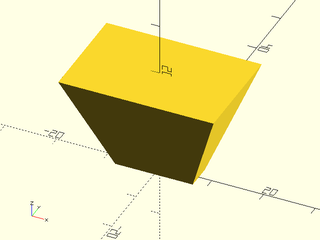
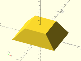
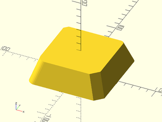
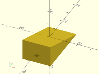
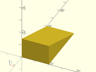
Example 1: Truncated Pyramid
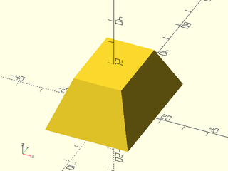
include <BOSL2/std.scad>
prismoid(size1=[35,50], size2=[20,30], h=20);
Example 2: Rectangular Pyramid
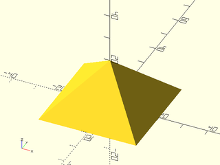
include <BOSL2/std.scad>
prismoid([40,40], [0,0], h=20);
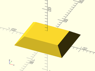
Example 3: Prism
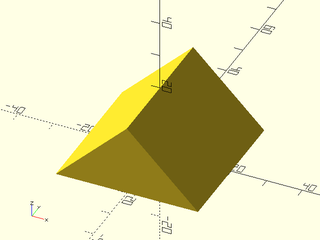
include <BOSL2/std.scad>
prismoid(size1=[40,40], size2=[0,40], h=20);
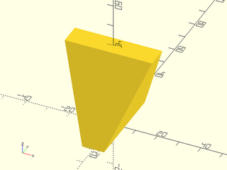
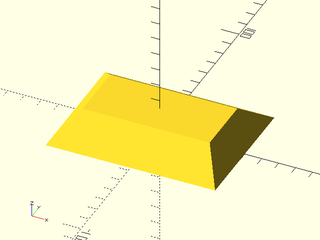
Example 4: Wedge
include <BOSL2/std.scad>
prismoid(size1=[60,35], size2=[30,0], h=30);
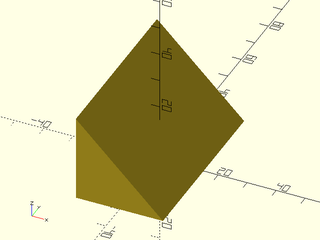
Example 5: Truncated Tetrahedron
include <BOSL2/std.scad>
prismoid(size1=[10,40], size2=[40,10], h=40);
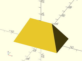
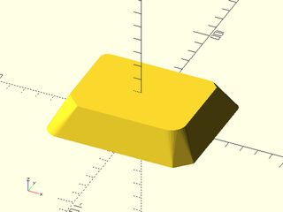
Example 6: Inverted Truncated Pyramid
include <BOSL2/std.scad>
prismoid(size1=[15,5], size2=[30,20], h=20);
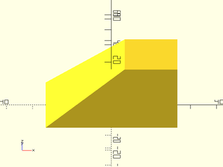
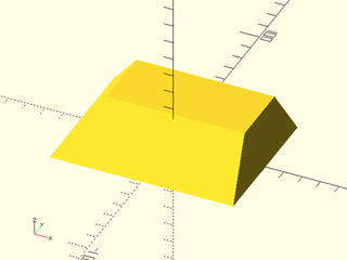
Example 7: Right Prism
include <BOSL2/std.scad>
prismoid(size1=[30,60], size2=[0,60], shift=[-15,0], h=30);
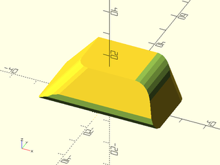
Example 8: Shifting/Skewing
include <BOSL2/std.scad>
prismoid(size1=[50,30], size2=[20,20], h=20, shift=[15,5]);
Example 9: Specifying bottom, height and angle
include <BOSL2/std.scad>
prismoid(size1=[100,75], h=30, xang=50, yang=70);
Example 10: Specifying top, height and angle, with asymmetric angles
include <BOSL2/std.scad>
prismoid(size2=[100,75], h=30, xang=[50,60], yang=[70,40]);
Example 11: Specifying top, bottom and angle for X and using that to define height. Note that giving yang here would likely give a conflicting height calculation, which is not allowed.
include <BOSL2/std.scad>
prismoid(size1=[100,75], size2=[75,35], xang=50);
Example 12: The same as the previous example but we give a shift in Y. Note that shift.x must be undef because you cannot give combine an angle with a shift, so a shift.x value would conflict with xang being defined.
include <BOSL2/std.scad>
prismoid(size1=[100,75], size2=[75,35], xang=50, shift=[undef,20]);
Example 13: The X dimensions defined by the base length, angle and height; the Y dimensions defined by the top length, angle, and height.
include <BOSL2/std.scad>
prismoid(size1=[100,undef], size2=[undef,75], h=30, xang=[20,90], yang=30);
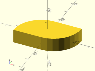
Example 14: Rounding
include <BOSL2/std.scad>
prismoid(100, 80, rounding=10, h=30);
Example 15: Chamfers
include <BOSL2/std.scad>
prismoid(100, 80, chamfer=5, h=30);
Example 16: Gradiant Rounding

include <BOSL2/std.scad>
prismoid(100, 80, rounding1=10, rounding2=0, h=30);
Example 17: Per Corner Rounding

include <BOSL2/std.scad>
prismoid(100, 80, rounding=[0,5,10,15], h=30);
Example 18: Per Corner Chamfer
include <BOSL2/std.scad>
prismoid(100, 80, chamfer=[0,5,10,15], h=30);
Example 19: Mixing Chamfer and Rounding
include <BOSL2/std.scad>
prismoid(
    100, 80, h=30,
    chamfer=[0,5,0,10],
    rounding=[5,0,10,0]
);
Example 20: Really Mixing It Up
include <BOSL2/std.scad>
prismoid(
    size1=[100,80], size2=[80,60], h=20,
    chamfer1=[0,5,0,10], chamfer2=[5,0,10,0],
    rounding1=[5,0,10,0], rounding2=[0,5,0,10]
);
Example 21: How to Round a Top or Bottom Edge
include <BOSL2/std.scad>
diff()
prismoid([50,30], [30,20], shift=[3,6], h=15, rounding=[5,0,5,0]) {
    edge_profile([TOP+RIGHT, BOT+FRONT], excess=10, convexity=20) {
        mask2d_roundover(h=5,mask_angle=$edge_angle);
    }
}
Example 22: Standard Connectors
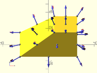
include <BOSL2/std.scad>
prismoid(size1=[50,30], size2=[20,20], h=20, shift=[15,5])
    show_anchors();
Synopsis: Creates an octahedron with axis-aligned points. [Geom] [VNF]
Topics: Shapes (3D), Attachable, VNF Generators
See Also: prismoid()
Usage: As Module
- octahedron(size, ...) [ATTACHMENTS];
Usage: As Function
- vnf = octahedron(size, ...);
Description:
When called as a module, creates an octahedron with axis-aligned points. When called as a function, creates a VNF of an octahedron with axis-aligned points.
Arguments:
| By Position | What it does |
|---|---|
size |
Width of the octahedron, tip to tip. |
| By Name | What it does |
|---|---|
anchor |
Translate so anchor point is at origin (0,0,0). See anchor. Default: CENTER
|
spin |
Rotate this many degrees around the Z axis after anchor. See spin. Default: 0
|
orient |
Vector to rotate top towards, after spin. See orient. Default: UP
|
Example 1:
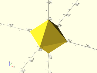
include <BOSL2/std.scad>
octahedron(size=40);
Example 2: Anchors
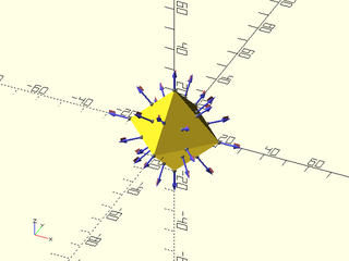
include <BOSL2/std.scad>
octahedron(size=40) show_anchors();
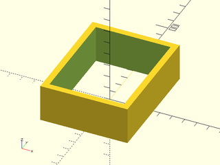
Synopsis: Creates a rectangular tube. [Geom]
Topics: Shapes (3D), Attachable, VNF Generators
See Also: tube()
Usage: Typical Rectangular Tubes
- rect_tube(h, size, isize, [center], [shift]);
- rect_tube(h, size, wall=, [center=]);
- rect_tube(h, isize=, wall=, [center=]);
Usage: Tapering Rectangular Tubes
- rect_tube(h, size1=, size2=, wall=, ...);
- rect_tube(h, isize1=, isize2=, wall=, ...);
- rect_tube(h, size1=, size2=, isize1=, isize2=, ...);
Usage: Chamfered
- rect_tube(h, size, isize, chamfer=, ...);
- rect_tube(h, size, isize, chamfer1=, chamfer2= ...);
- rect_tube(h, size, isize, ichamfer=, ...);
- rect_tube(h, size, isize, ichamfer1=, ichamfer2= ...);
- rect_tube(h, size, isize, chamfer=, ichamfer=, ...);
Usage: Rounded
- rect_tube(h, size, isize, rounding=, ...);
- rect_tube(h, size, isize, rounding1=, rounding2= ...);
- rect_tube(h, size, isize, irounding=, ...);
- rect_tube(h, size, isize, irounding1=, irounding2= ...);
- rect_tube(h, size, isize, rounding=, irounding=, ...);
Usage: Attaching Children
- rect_tube(...) ATTACHMENTS;
Description:
Creates a rectangular or prismoid tube with optional roundovers and/or chamfers. You can only round or chamfer the vertical(ish) edges. For those edges, you can specify rounding and/or chamferring per-edge, and for top and bottom, inside and outside separately.
By default if you specify a chamfer or rounding then it applies as specified to the
outside, and an inside rounding is calculated that will maintain constant width
if your wall thickness is uniform. If the wall thickness is not uniform, the default
inside rounding is calculated based on the smaller of the two wall thicknesses.
Note that the values of the more specific chamfers and roundings inherit from the
more general ones, so rounding2 is determined from rounding. The constant
width default will apply when the inner rounding and chamfer are both undef.
You can give an inner chamfer or rounding as a list with undef entries if you want to specify
some corner roundings and allow others to be computed.
Arguments:
| By Position | What it does |
|---|---|
h / l / height / length
|
The height or length of the rectangular tube. Default: 1 |
size |
The outer [X,Y] size of the rectangular tube. |
isize |
The inner [X,Y] size of the rectangular tube. |
center |
If given, overrides anchor. A true value sets anchor=CENTER, false sets anchor=UP. |
shift |
[X,Y] amount to shift the center of the top end with respect to the center of the bottom end. |
| By Name | What it does |
|---|---|
wall |
The thickness of the rectangular tube wall. |
size1 |
The [X,Y] size of the outside of the bottom of the rectangular tube. |
size2 |
The [X,Y] size of the outside of the top of the rectangular tube. |
isize1 |
The [X,Y] size of the inside of the bottom of the rectangular tube. |
isize2 |
The [X,Y] size of the inside of the top of the rectangular tube. |
rounding |
The roundover radius for the outside edges of the rectangular tube. |
rounding1 |
The roundover radius for the outside bottom corner of the rectangular tube. |
rounding2 |
The roundover radius for the outside top corner of the rectangular tube. |
chamfer |
The chamfer size for the outside edges of the rectangular tube. |
chamfer1 |
The chamfer size for the outside bottom corner of the rectangular tube. |
chamfer2 |
The chamfer size for the outside top corner of the rectangular tube. |
irounding |
The roundover radius for the inside edges of the rectangular tube. Default: Computed for uniform wall thickness (see above) |
irounding1 |
The roundover radius for the inside bottom corner of the rectangular tube. |
irounding2 |
The roundover radius for the inside top corner of the rectangular tube. |
ichamfer |
The chamfer size for the inside edges of the rectangular tube. Default: Computed for uniform wall thickness (see above) |
ichamfer1 |
The chamfer size for the inside bottom corner of the rectangular tube. |
ichamfer2 |
The chamfer size for the inside top corner of the rectangular tube. |
anchor |
Translate so anchor point is at origin (0,0,0). See anchor. Default: BOTTOM
|
spin |
Rotate this many degrees around the Z axis after anchor. See spin. Default: 0
|
orient |
Vector to rotate top towards, after spin. See orient. Default: UP
|
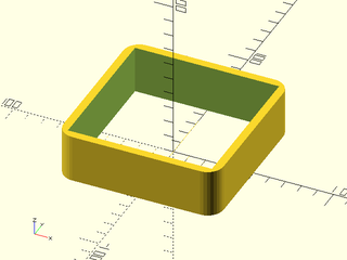
Example 1:
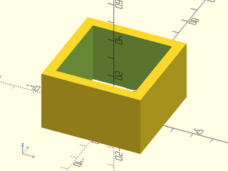
include <BOSL2/std.scad>
rect_tube(size=50, wall=5, h=30);
Example 2:
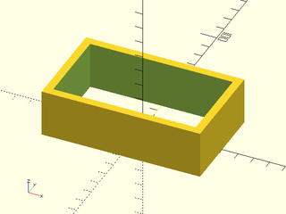
include <BOSL2/std.scad>
rect_tube(size=[100,60], wall=5, h=30);
Example 3:
include <BOSL2/std.scad>
rect_tube(isize=[60,80], wall=5, h=30);
Example 4:

include <BOSL2/std.scad>
rect_tube(size=[100,60], isize=[90,50], h=30);
Example 5:
include <BOSL2/std.scad>
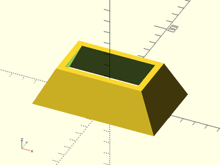
rect_tube(size1=[100,60], size2=[70,40], wall=5, h=30);
Example 6:
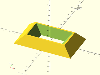
include <BOSL2/std.scad>
rect_tube(
    size1=[100,60], size2=[70,40],
    isize1=[40,20], isize2=[65,35], h=15
);
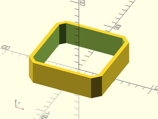
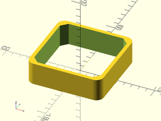
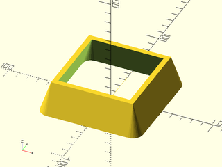
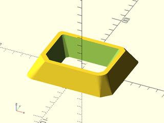
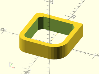
Example 7: With rounding
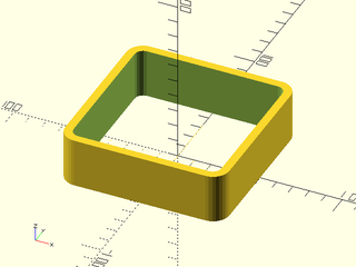
include <BOSL2/std.scad>
rect_tube(size=100, wall=5, rounding=10, h=30);
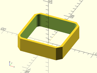
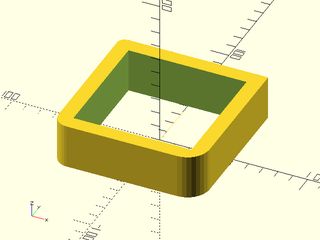
Example 8: With rounding
include <BOSL2/std.scad>
rect_tube(size=100, wall=5, chamfer=10, h=30);
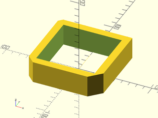
Example 9: Outer Rounding Only
include <BOSL2/std.scad>
rect_tube(size=100, wall=5, rounding=10, irounding=0, h=30);
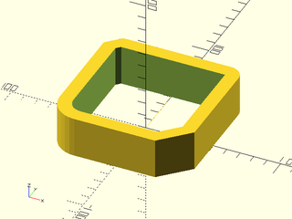
Example 10: Outer Chamfer Only

include <BOSL2/std.scad>
rect_tube(size=100, wall=5, chamfer=5, ichamfer=0, h=30);
Example 11: Outer Rounding, Inner Chamfer
include <BOSL2/std.scad>
rect_tube(size=100, wall=5, rounding=10, ichamfer=8, h=30);
Example 12: Inner Rounding, Outer Chamfer
include <BOSL2/std.scad>
rect_tube(size=100, wall=5, chamfer=10, irounding=8, h=30);
Example 13: Gradiant Rounding
include <BOSL2/std.scad>
rect_tube(
    size1=100, size2=80, wall=5, h=30,
    rounding1=10, rounding2=0,
    irounding1=8, irounding2=0
);
Example 14: Per Corner Rounding
include <BOSL2/std.scad>
rect_tube(
    size=100, wall=10, h=30,
    rounding=[0,5,10,15], irounding=0
);
Example 15: Per Corner Chamfer
include <BOSL2/std.scad>
rect_tube(
    size=100, wall=10, h=30,
    chamfer=[0,5,10,15], ichamfer=0
);
Example 16: Mixing Chamfer and Rounding
include <BOSL2/std.scad>
rect_tube(
    size=100, wall=10, h=30,
    chamfer=[0,10,0,20],
    rounding=[10,0,20,0]
);
Example 17: Really Mixing It Up
include <BOSL2/std.scad>
rect_tube(
    size1=[100,80], size2=[80,60],
    isize1=[50,30], isize2=[70,50], h=20,
    chamfer1=[0,5,0,10], ichamfer1=[0,3,0,8],
    chamfer2=[5,0,10,0], ichamfer2=[3,0,8,0],
    rounding1=[5,0,10,0], irounding1=[3,0,8,0],
    rounding2=[0,5,0,10], irounding2=[0,3,0,8]
);
Example 18: Some interiors chamfered, others with default rounding
include <BOSL2/std.scad>
rect_tube(
    size=100, wall=10, h=30,
    rounding=[0,10,20,30], ichamfer=[8,8,undef,undef]
);
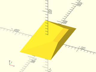
Synopsis: Creates a 3d triangular wedge. [Geom] [VNF]
Topics: Shapes (3D), Attachable, VNF Generators
Usage: As Module
- wedge(size, [center], ...) [ATTACHMENTS];
Usage: As Function
- vnf = wedge(size, [center], ...);
Description:
When called as a module, creates a 3D triangular wedge with the hypotenuse in the X+Z+ quadrant. When called as a function, creates a VNF for a 3D triangular wedge with the hypotenuse in the X+Z+ quadrant.
Arguments:
| By Position | What it does |
|---|---|
size |
[width, thickness, height] |
center |
If given, overrides anchor. A true value sets anchor=CENTER, false sets anchor=UP. |
| By Name | What it does |
|---|---|
anchor |
Translate so anchor point is at origin (0,0,0). See anchor. Default: FRONT+LEFT+BOTTOM
|
spin |
Rotate this many degrees around the Z axis after anchor. See spin. Default: 0
|
orient |
Vector to rotate top towards, after spin. See orient. Default: UP
|
Extra Anchors:
| Anchor Name | Position |
|---|---|
| hypot | Center of angled wedge face, perpendicular to that face. |
| hypot_left | Left side of angled wedge face, bisecting the angle between the left side and angled faces. |
| hypot_right | Right side of angled wedge face, bisecting the angle between the right side and angled faces. |
Example 1: Centered
include <BOSL2/std.scad>
wedge([20, 40, 15], center=true);
Example 2: Non-Centered
include <BOSL2/std.scad>
wedge([20, 40, 15]);
Example 3: Standard Anchors
include <BOSL2/std.scad>
wedge([40, 80, 30], center=true)
    show_anchors(custom=false);
color([0.5,0.5,0.5,0.1])
    cube([40, 80, 30], center=true);
Example 4: Named Anchors
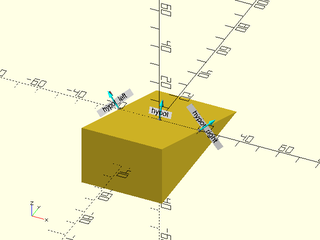
include <BOSL2/std.scad>
wedge([40, 80, 30], center=true)
    show_anchors(std=false);
Synopsis: Creates an attachable cylinder. [Geom] [VNF] [Ext]
Topics: Shapes (3D), Attachable, VNF Generators
See Also: cyl()
Usage: As Module (as in native OpenSCAD)
- cylinder(h, r=/d=, [center=]);
- cylinder(h, r1/d1=, r2/d2=, [center=]);
Usage: With BOSL2 anchoring and attachment extensions
- cylinder(h, r=/d=, [center=], [anchor=], [spin=], [orient=]) [ATTACHMENTS];
- cylinder(h, r1/d1=, r2/d2=, [center=], [anchor=], [spin=], [orient=]) [ATTACHMENTS];
Usage: As Function (BOSL2 extension)
- vnf = cylinder(h, r=/d=, ...);
- vnf = cylinder(h, r1/d1=, r2/d2=, ...);
Description:
Creates a 3D cylinder or conic object.
This modules extends the built-in cylinder() module by adding support for attachment and by adding a function version.
When called as a function, returns a VNF for a cylinder.
Arguments:
| By Position | What it does |
|---|---|
h |
The height of the cylinder. |
r1 |
The bottom radius of the cylinder. (Before orientation.) |
r2 |
The top radius of the cylinder. (Before orientation.) |
center |
If given, overrides anchor. A true value sets anchor=CENTER, false sets anchor=BOTTOM. Default: false |
| By Name | What it does |
|---|---|
d1 |
The bottom diameter of the cylinder. (Before orientation.) |
d2 |
The top diameter of the cylinder. (Before orientation.) |
r |
The radius of the cylinder. |
d |
The diameter of the cylinder. |
anchor |
Translate so anchor point is at origin (0,0,0). See anchor. Default: CENTER
|
spin |
Rotate this many degrees around the Z axis after anchor. See spin. Default: 0
|
orient |
Vector to rotate top towards, after spin. See orient. Default: UP
|
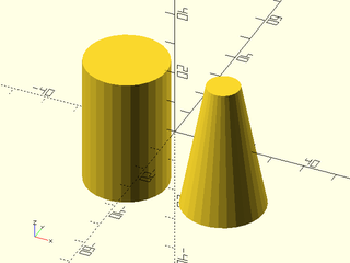
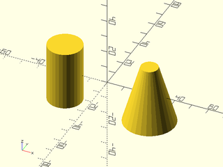
Example 1: By Radius
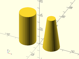
include <BOSL2/std.scad>
xdistribute(30) {
    cylinder(h=40, r=10);
    cylinder(h=40, r1=10, r2=5);
}
Example 2: By Diameter
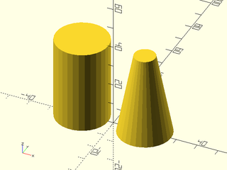
include <BOSL2/std.scad>
xdistribute(30) {
    cylinder(h=40, d=25);
    cylinder(h=40, d1=25, d2=10);
}
Example 3: Anchoring
include <BOSL2/std.scad>
cylinder(h=40, r1=10, r2=5, anchor=BOTTOM+FRONT);
Example 4: Spin
include <BOSL2/std.scad>
cylinder(h=40, r1=10, r2=5, anchor=BOTTOM+FRONT, spin=45);
Example 5: Orient
include <BOSL2/std.scad>
cylinder(h=40, r1=10, r2=5, anchor=BOTTOM+FRONT, spin=45, orient=FWD);
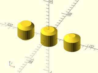
Example 6: Standard Connectors
include <BOSL2/std.scad>
xdistribute(40) {
    cylinder(h=30, d=25) show_anchors();
    cylinder(h=30, d1=25, d2=10) show_anchors();
}
Synopsis: Creates an attachable cylinder with roundovers and chamfering. [Geom] [VNF]
Topics: Cylinders, Textures, Rounding, Chamfers
See Also: texture(), rotate_sweep(), cylinder()
Usage: Normal Cylinders
- cyl(l|h|length|height, r, [center], [circum=], [realign=]) [ATTACHMENTS];
- cyl(l|h|length|height, d=, ...) [ATTACHMENTS];
- cyl(l|h|length|height, r1=, r2=, ...) [ATTACHMENTS];
- cyl(l|h|length|height, d1=, d2=, ...) [ATTACHMENTS];
Usage: Chamferred Cylinders
- cyl(l|h|length|height, r|d, chamfer=, [chamfang=], [from_end=], ...);
- cyl(l|h|length|height, r|d, chamfer1=, [chamfang1=], [from_end=], ...);
- cyl(l|h|length|height, r|d, chamfer2=, [chamfang2=], [from_end=], ...);
- cyl(l|h|length|height, r|d, chamfer1=, chamfer2=, [chamfang1=], [chamfang2=], [from_end=], ...);
Usage: Rounded End Cylinders
- cyl(l|h|length|height, r|d, rounding=, ...);
- cyl(l|h|length|height, r|d, rounding1=, ...);
- cyl(l|h|length|height, r|d, rounding2=, ...);
- cyl(l|h|length|height, r|d, rounding1=, rounding2=, ...);
Usage: Textured Cylinders
- cyl(l|h|length|height, r|d, texture=, [tex_size=]|[tex_reps=], [tex_depth=], [tex_rot=], [tex_samples=], [style=], [tex_taper=], [tex_inset=], ...);
- cyl(l|h|length|height, r1=, r2=, texture=, [tex_size=]|[tex_reps=], [tex_depth=], [tex_rot=], [tex_samples=], [style=], [tex_taper=], [tex_inset=], ...);
- cyl(l|h|length|height, d1=, d2=, texture=, [tex_size=]|[tex_reps=], [tex_depth=], [tex_rot=], [tex_samples=], [style=], [tex_taper=], [tex_inset=], ...);
Usage: Caled as a function to get a VNF
- vnf = cyl(...);
Description:
Creates cylinders in various anchorings and orientations, with optional rounding, chamfers, or textures.
You can use h and l interchangably, and all variants allow specifying size by either r|d,
or r1|d1 and r2|d2. Note: the chamfers and rounding cannot be cumulatively longer than
the cylinder or cone's sloped side. The more specific parameters like chamfer1 or rounding2 override the more
general ones like chamfer or rounding, so if you specify rounding=3, chamfer2=3 you will get a chamfer at the top and
rounding at the bottom.
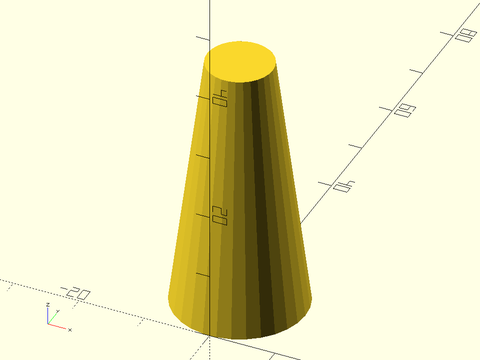
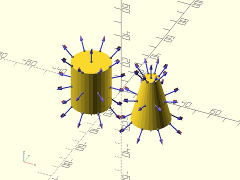
Figure 1: Chamfers on cones can be tricky. This figure shows chamfers of the same size and same angle, A=30 degrees. Note that the angle is measured on the inside, and produces a quite different looking chamfer at the top and bottom of the cone. Straight black arrows mark the size of the chamfers, which may not even appear the same size visually. When you do not give an angle, the triangle that is cut off will be isoceles, like the triangle at the top, with two equal angles.

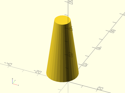
Figure 2: The cone in this example is narrow but has the same slope. With negative chamfers, the angle A=30 degrees is on the outside. The chamfers are again quite different looking. As before, the default will feature two congruent angles, and in this case it happens at the bottom of the cone but not the top. The straight arrows again show the size of the chamfer.

Arguments:
| By Position | What it does |
|---|---|
l / h / length / height
|
Length of cylinder along oriented axis. Default: 1 |
r |
Radius of cylinder. Default: 1 |
center |
If given, overrides anchor. A true value sets anchor=CENTER, false sets anchor=DOWN. |
| By Name | What it does |
|---|---|
r1 |
Radius of the negative (X-, Y-, Z-) end of cylinder. |
r2 |
Radius of the positive (X+, Y+, Z+) end of cylinder. |
d |
Diameter of cylinder. |
d1 |
Diameter of the negative (X-, Y-, Z-) end of cylinder. |
d2 |
Diameter of the positive (X+, Y+, Z+) end of cylinder. |
circum |
If true, cylinder should circumscribe the circle of the given size. Otherwise inscribes. Default: false
|
shift |
[X,Y] amount to shift the center of the top end with respect to the center of the bottom end. |
chamfer |
The size of the chamfers on the ends of the cylinder. (Also see: from_end=) Default: none. |
chamfer1 |
The size of the chamfer on the bottom end of the cylinder. (Also see: from_end1=) Default: none. |
chamfer2 |
The size of the chamfer on the top end of the cylinder. (Also see: from_end2=) Default: none. |
chamfang |
The angle in degrees of the chamfers away from the ends of the cylinder. Default: Chamfer angle is halfway between the endcap and cone face. |
chamfang1 |
The angle in degrees of the bottom chamfer away from the bottom end of the cylinder. Default: Chamfer angle is halfway between the endcap and cone face. |
chamfang2 |
The angle in degrees of the top chamfer away from the top end of the cylinder. Default: Chamfer angle is halfway between the endcap and cone face. |
from_end |
If true, chamfer is measured along the conic face from the ends of the cylinder, instead of inset from the edge. Default: false. |
from_end1 |
If true, chamfer on the bottom end of the cylinder is measured along the conic face from the end of the cylinder, instead of inset from the edge. Default: false. |
from_end2 |
If true, chamfer on the top end of the cylinder is measured along the conic face from the end of the cylinder, instead of inset from the edge. Default: false. |
rounding |
The radius of the rounding on the ends of the cylinder. Default: none. |
rounding1 |
The radius of the rounding on the bottom end of the cylinder. |
rounding2 |
The radius of the rounding on the top end of the cylinder. |
realign |
If true, rotate the cylinder by half the angle of one face. |
teardrop |
If given as a number, rounding around the bottom edge of the cylinder won't exceed this many degrees from vertical. If true, the limit angle is 45 degrees. Default: false
|
texture |
A texture name string, or a rectangular array of scalar height values (0.0 to 1.0), or a VNF tile that defines the texture to apply to vertical surfaces. See texture() for what named textures are supported. |
tex_size |
An optional 2D target size for the textures. Actual texture sizes will be scaled somewhat to evenly fit the available surface. Default: [5,5]
|
tex_reps |
If given instead of tex_size, a 2-vector giving the number of texture tile repetitions in the horizontal and vertical directions. |
tex_inset |
If numeric, lowers the texture into the surface by the specified proportion, e.g. 0.5 would lower it half way into the surface. If true, insets by exactly its full depth. Default: false
|
tex_rot |
Rotate texture by specified angle, which must be a multiple of 90 degrees. Default: 0 |
tex_depth |
Specify texture depth; if negative, invert the texture. Default: 1. |
tex_samples |
Minimum number of "bend points" to have in VNF texture tiles. Default: 8 |
tex_taper |
If given as a number, tapers the texture height to zero over the first and last given percentage of the path. If given as a lookup table with indices between 0 and 100, uses the percentage lookup table to ramp the texture heights. Default: undef (no taper) |
style |
vnf_vertex_array() style used to triangulate heightfield textures. Default: "min_edge" |
anchor |
Translate so anchor point is at origin (0,0,0). See anchor. Default: CENTER
|
spin |
Rotate this many degrees around the Z axis after anchor. See spin. Default: 0
|
orient |
Vector to rotate top towards, after spin. See orient. Default: UP
|
Example 1: By Radius

include <BOSL2/std.scad>
xdistribute(30) {
    cyl(l=40, r=10);
    cyl(l=40, r1=10, r2=5);
}
Example 2: By Diameter
include <BOSL2/std.scad>
xdistribute(30) {
    cyl(l=40, d=25);
    cyl(l=40, d1=25, d2=10);
}
Example 3: Chamferring
include <BOSL2/std.scad>
xdistribute(60) {
    // Shown Left to right.
    cyl(l=40, d=40, chamfer=7);  // Default chamfang=45
    cyl(l=40, d=40, chamfer=7, chamfang=30, from_end=false);
    cyl(l=40, d=40, chamfer=7, chamfang=30, from_end=true);
}
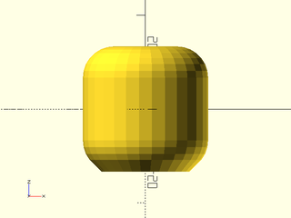
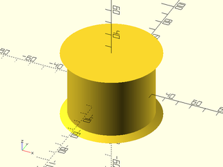
Example 4: Rounding
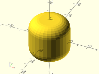
include <BOSL2/std.scad>
cyl(l=40, d=40, rounding=10);
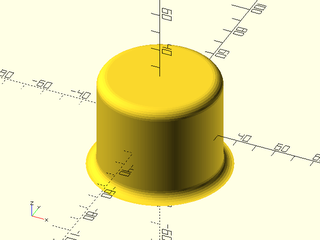
Example 5: Teardrop Bottom Rounding
include <BOSL2/std.scad>
cyl(l=40, d=40, rounding=10, teardrop=true);
Example 6: Heterogenous Chamfers and Rounding
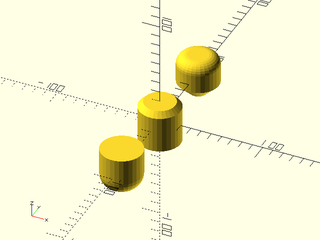
include <BOSL2/std.scad>
ydistribute(80) {
    // Shown Front to Back.
    cyl(l=40, d=40, rounding1=15, orient=UP);
    cyl(l=40, d=40, chamfer2=5, orient=UP);
    cyl(l=40, d=40, chamfer1=12, rounding2=10, orient=UP);
}
Example 7: Putting it all together
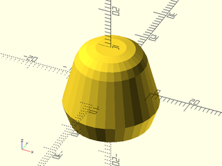
include <BOSL2/std.scad>
cyl(
    l=20, d1=25, d2=15,
    chamfer1=5, chamfang1=60,
    from_end=true, rounding2=5
);
Example 8: External Chamfers
include <BOSL2/std.scad>
cyl(l=50, r=30, chamfer=-5, chamfang=30, $fa=1, $fs=1);
Example 9: External Roundings
include <BOSL2/std.scad>
cyl(l=50, r=30, rounding1=-5, rounding2=5, $fa=1, $fs=1);
Example 10: Standard Connectors
include <BOSL2/std.scad>
xdistribute(40) {
    cyl(l=30, d=25) show_anchors();
    cyl(l=30, d1=25, d2=10) show_anchors();
}
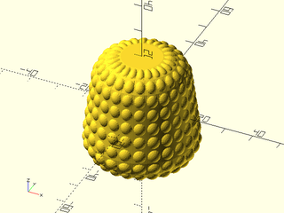
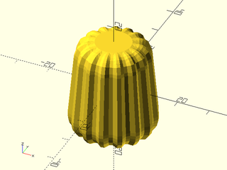
Example 11: Texturing with heightfield diamonds
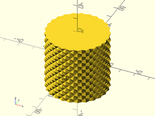
include <BOSL2/std.scad>
cyl(h=40, r=20, texture="diamonds", tex_size=[5,5]);
Example 12: Texturing with heightfield pyramids
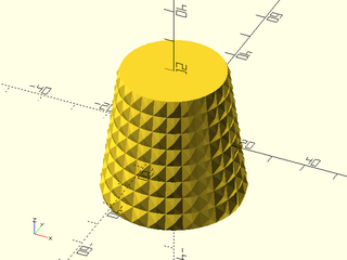
include <BOSL2/std.scad>
cyl(h=40, r1=20, r2=15,
    texture="pyramids", tex_size=[5,5],
    style="convex");
Example 13: Texturing with heightfield truncated pyramids
include <BOSL2/std.scad>
cyl(h=40, r1=20, r2=15, chamfer=5,
    texture="trunc_pyramids",
    tex_size=[5,5], style="convex");
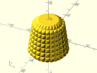
Example 14: Texturing with VNF tile "dots"
include <BOSL2/std.scad>
cyl(h=40, r1=20, r2=15, rounding=9,
    texture="dots", tex_size=[5,5],
    tex_samples=6);
Example 15: Texturing with VNF tile "bricks_vnf"
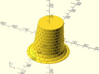
include <BOSL2/std.scad>
cyl(h=50, r1=25, r2=20, shift=[0,10], rounding1=-10,
    texture="bricks_vnf", tex_size=[10,10],
    tex_depth=0.5, style="concave");
Example 16: No Texture Taper
include <BOSL2/std.scad>
cyl(d1=25, d2=20, h=30, rounding=5,
    texture="trunc_ribs", tex_size=[5,1]);
Example 17: Taper Texure at Extreme Ends
include <BOSL2/std.scad>
cyl(d1=25, d2=20, h=30, rounding=5,
    texture="trunc_ribs", tex_taper=0,
    tex_size=[5,1]);
Example 18: Taper Texture over First and Last 10%
include <BOSL2/std.scad>
cyl(d1=25, d2=20, h=30, rounding=5,
    texture="trunc_ribs", tex_taper=10,
    tex_size=[5,1]);
Example 19: Making a Clay Pattern Roller
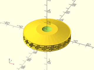
include <BOSL2/std.scad>
tex = [
    [0,0,0,0,0,0,0,0,0,0,0,0,0,0,0,0,],
    [0,0,0,0,0,0,0,0,0,0,0,0,0,0,0,0,],
    [1,1,1,0,0,1,1,1,1,1,1,1,1,1,1,1,],
    [1,1,1,0,0,1,1,1,1,1,1,1,1,1,1,1,],
    [0,1,1,0,0,1,1,0,0,0,0,0,0,0,0,0,],
    [0,1,1,0,0,1,1,0,0,0,0,0,0,0,0,0,],
    [0,1,1,0,0,1,1,0,0,1,1,1,1,1,1,0,],
    [0,1,1,0,0,1,1,0,0,1,1,1,1,1,1,0,],
    [0,1,1,0,0,1,1,0,0,1,1,0,0,1,1,0,],
    [0,1,1,0,0,1,1,0,0,1,1,0,0,1,1,0,],
    [0,1,1,0,0,1,1,1,1,1,1,0,0,1,1,0,],
    [0,1,1,0,0,1,1,1,1,1,1,0,0,1,1,0,],
    [0,1,1,0,0,0,0,0,0,0,0,0,0,1,1,0,],
    [0,1,1,0,0,0,0,0,0,0,0,0,0,1,1,0,],
    [0,1,1,1,1,1,1,1,1,1,1,1,1,1,1,0,],
    [0,1,1,1,1,1,1,1,1,1,1,1,1,1,1,0,],
    [0,0,0,0,0,0,0,0,0,0,0,0,0,0,0,0,],
];
diff()
cyl(d=20*10/PI, h=10, chamfer=0,
    texture=tex, tex_reps=[20,1], tex_depth=-1,
    tex_taper=undef, style="concave") {
        attach([TOP,BOT]) {
            cyl(d1=20*10/PI, d2=30, h=5, anchor=BOT)
                attach(TOP) {
                    tag("remove") zscale(0.5) up(3) sphere(d=15);
                }
        }
}
Synopsis: creates a cylinder oriented along the X axis. [Geom]
Topics: Cylinders, Textures, Rounding, Chamfers
See Also: texture(), rotate_sweep(), cyl()
Usage: Typical
- xcyl(l|h|length|height, r|d=, [anchor=], ...) [ATTACHMENTS];
- xcyl(l|h|length|height, r1=|d1=, r2=|d2=, [anchor=], ...) [ATTACHMENTS];
Description:
Creates an attachable cylinder with roundovers and chamfering oriented along the X axis.
Arguments:
| By Position | What it does |
|---|---|
l / h / length / height
|
Length of cylinder along oriented axis. Default: 1 |
r |
Radius of cylinder. Default: 1 |
| By Name | What it does |
|---|---|
r1 |
Optional radius of left (X-) end of cylinder. |
r2 |
Optional radius of right (X+) end of cylinder. |
d |
Optional diameter of cylinder. (use instead of r) |
d1 |
Optional diameter of left (X-) end of cylinder. |
d2 |
Optional diameter of right (X+) end of cylinder. |
circum |
If true, cylinder should circumscribe the circle of the given size. Otherwise inscribes. Default: false
|
chamfer |
The size of the chamfers on the ends of the cylinder. Default: none. |
chamfer1 |
The size of the chamfer on the left end of the cylinder. Default: none. |
chamfer2 |
The size of the chamfer on the right end of the cylinder. Default: none. |
chamfang |
The angle in degrees of the chamfers on the ends of the cylinder. |
chamfang1 |
The angle in degrees of the chamfer on the left end of the cylinder. |
chamfang2 |
The angle in degrees of the chamfer on the right end of the cylinder. |
from_end |
If true, chamfer is measured from the end of the cylinder, instead of inset from the edge. Default: false. |
rounding |
The radius of the rounding on the ends of the cylinder. Default: none. |
rounding1 |
The radius of the rounding on the left end of the cylinder. |
rounding2 |
The radius of the rounding on the right end of the cylinder. |
realign |
If true, rotate the cylinder by half the angle of one face. |
anchor |
Translate so anchor point is at origin (0,0,0). See anchor. Default: CENTER
|
spin |
Rotate this many degrees around the Z axis after anchor. See spin. Default: 0
|
orient |
Vector to rotate top towards, after spin. See orient. Default: UP
|
Example 1: By Radius
include <BOSL2/std.scad>
ydistribute(50) {
    xcyl(l=35, r=10);
    xcyl(l=35, r1=15, r2=5);
}
Example 2: By Diameter

include <BOSL2/std.scad>
ydistribute(50) {
    xcyl(l=35, d=20);
    xcyl(l=35, d1=30, d2=10);
}
Synopsis: Creates a cylinder oriented along the y axis. [Geom]
Topics: Cylinders, Textures, Rounding, Chamfers
See Also: texture(), rotate_sweep(), cyl()
Usage: Typical
- ycyl(l|h|length|height, r|d=, [anchor=], ...) [ATTACHMENTS];
- ycyl(l|h|length|height, r1=|d1=, r2=|d2=, [anchor=], ...) [ATTACHMENTS];
Description:
Creates an attachable cylinder with roundovers and chamfering oriented along the y axis.
Arguments:
| By Position | What it does |
|---|---|
l / h / length / height
|
Length of cylinder along oriented axis. (Default: 1.0) |
r |
Radius of cylinder. |
| By Name | What it does |
|---|---|
r1 |
Radius of front (Y-) end of cone. |
r2 |
Radius of back (Y+) end of one. |
d |
Diameter of cylinder. |
d1 |
Diameter of front (Y-) end of one. |
d2 |
Diameter of back (Y+) end of one. |
circum |
If true, cylinder should circumscribe the circle of the given size. Otherwise inscribes. Default: false
|
chamfer |
The size of the chamfers on the ends of the cylinder. Default: none. |
chamfer1 |
The size of the chamfer on the front end of the cylinder. Default: none. |
chamfer2 |
The size of the chamfer on the back end of the cylinder. Default: none. |
chamfang |
The angle in degrees of the chamfers on the ends of the cylinder. |
chamfang1 |
The angle in degrees of the chamfer on the front end of the cylinder. |
chamfang2 |
The angle in degrees of the chamfer on the back end of the cylinder. |
from_end |
If true, chamfer is measured from the end of the cylinder, instead of inset from the edge. Default: false. |
rounding |
The radius of the rounding on the ends of the cylinder. Default: none. |
rounding1 |
The radius of the rounding on the front end of the cylinder. |
rounding2 |
The radius of the rounding on the back end of the cylinder. |
realign |
If true, rotate the cylinder by half the angle of one face. |
anchor |
Translate so anchor point is at origin (0,0,0). See anchor. Default: CENTER
|
spin |
Rotate this many degrees around the Z axis after anchor. See spin. Default: 0
|
orient |
Vector to rotate top towards, after spin. See orient. Default: UP
|
Example 1: By Radius

include <BOSL2/std.scad>
xdistribute(50) {
    ycyl(l=35, r=10);
    ycyl(l=35, r1=15, r2=5);
}
Example 2: By Diameter
include <BOSL2/std.scad>
xdistribute(50) {
    ycyl(l=35, d=20);
    ycyl(l=35, d1=30, d2=10);
}
Synopsis: Creates a cylinder oriented along the Z axis. [Geom]
Topics: Cylinders, Textures, Rounding, Chamfers
See Also: texture(), rotate_sweep(), cyl()
Usage: Typical
- zcyl(l|h|length|height, r|d=, [anchor=],...) [ATTACHMENTS];
- zcyl(l|h|length|height, r1=|d1=, r2=|d2=, [anchor=],...);
Description:
Creates an attachable cylinder with roundovers and chamfering oriented along the Z axis.
Arguments:
| By Position | What it does |
|---|---|
l / h / length / height
|
Length of cylinder along oriented axis. (Default: 1.0) |
r |
Radius of cylinder. |
| By Name | What it does |
|---|---|
r1 |
Radius of front (Y-) end of cone. |
r2 |
Radius of back (Y+) end of one. |
d |
Diameter of cylinder. |
d1 |
Diameter of front (Y-) end of one. |
d2 |
Diameter of back (Y+) end of one. |
circum |
If true, cylinder should circumscribe the circle of the given size. Otherwise inscribes. Default: false
|
chamfer |
The size of the chamfers on the ends of the cylinder. Default: none. |
chamfer1 |
The size of the chamfer on the bottom end of the cylinder. Default: none. |
chamfer2 |
The size of the chamfer on the top end of the cylinder. Default: none. |
chamfang |
The angle in degrees of the chamfers on the ends of the cylinder. |
chamfang1 |
The angle in degrees of the chamfer on the bottom end of the cylinder. |
chamfang2 |
The angle in degrees of the chamfer on the top end of the cylinder. |
from_end |
If true, chamfer is measured from the end of the cylinder, instead of inset from the edge. Default: false. |
rounding |
The radius of the rounding on the ends of the cylinder. Default: none. |
rounding1 |
The radius of the rounding on the bottom end of the cylinder. |
rounding2 |
The radius of the rounding on the top end of the cylinder. |
realign |
If true, rotate the cylinder by half the angle of one face. |
anchor |
Translate so anchor point is at origin (0,0,0). See anchor. Default: CENTER
|
spin |
Rotate this many degrees around the Z axis after anchor. See spin. Default: 0
|
orient |
Vector to rotate top towards, after spin. See orient. Default: UP
|
Example 1: By Radius

include <BOSL2/std.scad>
xdistribute(50) {
    zcyl(l=35, r=10);
    zcyl(l=35, r1=15, r2=5);
}
Example 2: By Diameter
include <BOSL2/std.scad>
xdistribute(50) {
    zcyl(l=35, d=20);
    zcyl(l=35, d1=30, d2=10);
}
Synopsis: Creates a cylindrical or conical tube. [Geom]
Topics: Shapes (3D), Attachable, VNF Generators
See Also: rect_tube()
Usage: Basic cylindrical tube, specifying inner and outer radius or diameter
- tube(h|l, or, ir, [center], [realign=], [anchor=], [spin=],[orient=]) [ATTACHMENTS];
- tube(h|l, od=, id=, ...) [ATTACHMENTS];
Usage: Specify wall thickness
- tube(h|l, or|od=|ir=|id=, wall=, ...) [ATTACHMENTS];
Usage: Conical tubes
- tube(h|l, ir1=|id1=, ir2=|id2=, or1=|od1=, or2=|od2=, ...) [ATTACHMENTS];
- tube(h|l, or1=|od1=, or2=|od2=, wall=, ...) [ATTACHMENTS];
Description:
Makes a hollow tube that can be cylindrical or conical by specifying inner and outer dimensions or by giving one dimension and wall thickness.
Arguments:
| By Position | What it does |
|---|---|
h / l
|
height of tube. Default: 1 |
or |
Outer radius of tube. Default: 1 |
ir |
Inner radius of tube. |
center |
If given, overrides anchor. A true value sets anchor=CENTER, false sets anchor=DOWN. |
| By Name | What it does |
|---|---|
od |
Outer diameter of tube. |
id |
Inner diameter of tube. |
wall |
horizontal thickness of tube wall. Default 1 |
or1 |
Outer radius of bottom of tube. Default: value of r) |
or2 |
Outer radius of top of tube. Default: value of r) |
od1 |
Outer diameter of bottom of tube. |
od2 |
Outer diameter of top of tube. |
ir1 |
Inner radius of bottom of tube. |
ir2 |
Inner radius of top of tube. |
id1 |
Inner diameter of bottom of tube. |
id2 |
Inner diameter of top of tube. |
realign |
If true, rotate the tube by half the angle of one face. |
anchor |
Translate so anchor point is at origin (0,0,0). See anchor. Default: CENTER
|
spin |
Rotate this many degrees around the Z axis after anchor. See spin. Default: 0
|
orient |
Vector to rotate top towards, after spin. See orient. Default: UP
|
Example 1: These all Produce the Same Tube
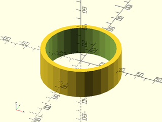
include <BOSL2/std.scad>
tube(h=30, or=40, wall=5);
tube(h=30, ir=35, wall=5);
tube(h=30, or=40, ir=35);
tube(h=30, od=80, id=70);
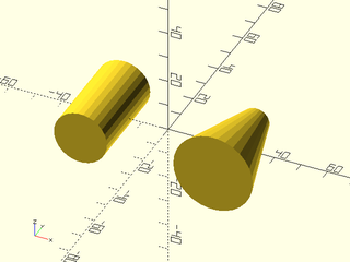
Example 2: These all Produce the Same Conical Tube
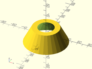
include <BOSL2/std.scad>
tube(h=30, or1=40, or2=25, wall=5);
tube(h=30, ir1=35, or2=20, wall=5);
tube(h=30, or1=40, or2=25, ir1=35, ir2=20);
Example 3: Circular Wedge
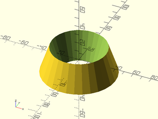
include <BOSL2/std.scad>
tube(h=30, or1=40, or2=30, ir1=20, ir2=30);
Example 4: Standard Connectors
include <BOSL2/std.scad>
tube(h=30, or=40, wall=5) show_anchors();
Synopsis: Creates a pie slice shape. [Geom] [VNF]
Topics: Shapes (3D), Attachable, VNF Generators
See Also: wedge()
Usage: As Module
- pie_slice(l|h=|height=|length=, r, ang, [center]);
- pie_slice(l|h=|height=|length=, d=, ang=, ...);
- pie_slice(l|h=|height=|length=, r1=|d1=, r2=|d2=, ang=, ...);
Usage: As Function
- vnf = pie_slice(l|h=|height=|length=, r, ang, [center]);
- vnf = pie_slice(l|h=|height=|length=, d=, ang=, ...);
- vnf = pie_slice(l|h=|height=|length=, r1=|d1=, r2=|d2=, ang=, ...);
Usage: Attaching Children
- pie_slice(l|h, r, ang, ...) ATTACHMENTS;
Description:
Creates a pie slice shape.
Arguments:
| By Position | What it does |
|---|---|
h / l / height / length
|
height of pie slice. |
r |
radius of pie slice. |
ang |
pie slice angle in degrees. |
center |
If given, overrides anchor. A true value sets anchor=CENTER, false sets anchor=UP. |
| By Name | What it does |
|---|---|
r1 |
bottom radius of pie slice. |
r2 |
top radius of pie slice. |
d |
diameter of pie slice. |
d1 |
bottom diameter of pie slice. |
d2 |
top diameter of pie slice. |
anchor |
Translate so anchor point is at origin (0,0,0). See anchor. Default: CENTER
|
spin |
Rotate this many degrees around the Z axis after anchor. See spin. Default: 0
|
orient |
Vector to rotate top towards, after spin. See orient. Default: UP
|
Example 1: Cylindrical Pie Slice
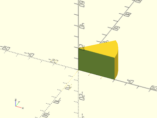
include <BOSL2/std.scad>
pie_slice(ang=45, l=20, r=30);
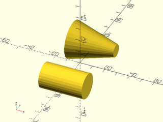
Example 2: Conical Pie Slice
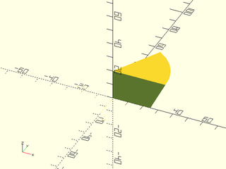
include <BOSL2/std.scad>
pie_slice(ang=60, l=20, d1=50, d2=70);
Example 3: Big Slice
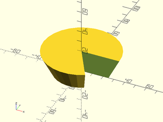
include <BOSL2/std.scad>
pie_slice(ang=300, l=20, d1=50, d2=70);
Example 4: Generating a VNF
include <BOSL2/std.scad>
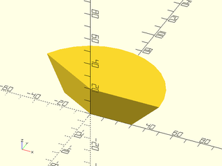
vnf = pie_slice(ang=150, l=20, r1=30, r2=50);
vnf_polyhedron(vnf);
Synopsis: Creates an attachable spherical object. [Geom] [VNF] [Ext]
Topics: Shapes (3D), Attachable, VNF Generators
See Also: spheroid()
Usage: As Module (native OpenSCAD)
- sphere(r|d=);
Usage: Using BOSL2 attachments extensions
- sphere(r|d=, [anchor=], [spin=], [orient=]) [ATTACHMENTS];
Usage: As Function (BOSL2 extension)
- vnf = sphere(r|d=, [anchor=], [spin=], [orient=]) [ATTACHMENTS];
Description:
Creates a sphere object.
This module extends the built-in sphere() module by providing support for BOSL2 anchoring and attachments, and a function form.
When called as a function, returns a VNF for a sphere.
Arguments:
| By Position | What it does |
|---|---|
r |
Radius of the sphere. |
| By Name | What it does |
|---|---|
d |
Diameter of the sphere. |
anchor |
Translate so anchor point is at origin (0,0,0). See anchor. Default: CENTER
|
spin |
Rotate this many degrees around the Z axis after anchor. See spin. Default: 0
|
orient |
Vector to rotate top towards, after spin. See orient. Default: UP
|
Example 1: By Radius

include <BOSL2/std.scad>
sphere(r=50);
Example 2: By Diameter

include <BOSL2/std.scad>
sphere(d=100);
Example 3: Anchoring

include <BOSL2/std.scad>
sphere(d=100, anchor=FRONT);
Example 4: Spin
include <BOSL2/std.scad>
sphere(d=100, anchor=FRONT, spin=45);
Example 5: Orientation
include <BOSL2/std.scad>
sphere(d=100, anchor=FRONT, spin=45, orient=FWD);
Example 6: Standard Connectors

include <BOSL2/std.scad>
sphere(d=50) show_anchors();
Synopsis: Creates an attachable spherical object with controllable triangulation. [Geom] [VNF]
Topics: Shapes (3D), Attachable, VNF Generators
See Also: sphere()
Usage: Typical
- spheroid(r|d, [circum], [style]) [ATTACHMENTS];
Usage: As Function
- vnf = spheroid(r|d, [circum], [style]);
Description:
Creates a spheroid object, with support for anchoring and attachments.
This is a drop-in replacement for the built-in sphere() module.
When called as a function, returns a VNF for a spheroid.
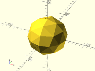
The exact triangulation of this spheroid can be controlled via the style=
argument, where the value can be one of "orig", "aligned", "stagger",
"octa", or "icosa".
-
style="orig"constructs a sphere the same way that the OpenSCADsphere()built-in does. -
style="aligned"constructs a sphere where, if$fnis a multiple of 4, it has vertices at all axis maxima and minima. ie: its bounding box is exactly the sphere diameter in length on all three axes. This is the default. -
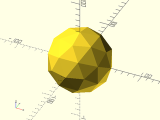
style="stagger"forms a sphere where all faces are triangular, but the top and bottom poles have thinner triangles. -
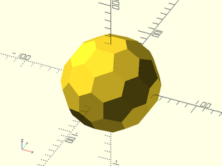
style="octa"forms a sphere by subdividing an octahedron. This makes more uniform faces over the entirety of the sphere, and guarantees the bounding box is the sphere diameter in size on all axes. The effective$fnvalue is quantized to a multiple of 4. This is used in constructing rounded corners for various other shapes. -
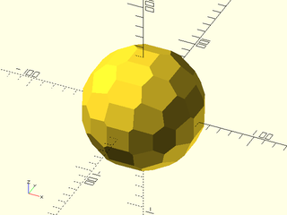
style="icosa"forms a sphere by subdividing an icosahedron. This makes even more uniform faces over the whole sphere. The effective$fnvalue is quantized to a multiple of 5. This sphere has a guaranteed bounding box when$fnis a multiple of 10.
By default the object spheroid() produces is a polyhedron whose vertices all lie on the requested sphere. This means
the approximating polyhedron is inscribed in the sphere.
The circum argument requests a circumscribing sphere, where the true sphere is
inside and tangent to all the faces of the approximating polyhedron. To produce
a circumscribing polyhedron, we use the dual polyhedron of the basic form. The dual of a polyhedron is
a new polyhedron whose vertices are obtained from the faces of the parent polyhedron.
The "orig" and "align" forms are duals of each other. If you request a circumscribing polyhedron in
these styles then the polyhedron will look the same as the default inscribing form. But for the other
styles, the duals are completely different from their parents, and from each other. Generation of the circumscribed versions (duals)
for "octa" and "icosa" is fast if you use the module form but can be very slow (several minutes) if you use the functional
form and choose a large $fn value.
With style="align", the circumscribed sphere has its maximum radius on the X and Y axes but is undersized on the Z axis. With style="octa" the circumscribed sphere has faces at each axis, so the radius on the axes is equal to the specified radius, which is the minimum radius of the circumscribed sphere. The same thing is true for style="icosa" when $fn is a multiple of 10. This would enable you to create spherical holes with guaranteed on-axis dimensions.
Arguments:
| By Position | What it does |
|---|---|
r |
Radius of the spheroid. |
style |
The style of the spheroid's construction. One of "orig", "aligned", "stagger", "octa", or "icosa". Default: "aligned" |
| By Name | What it does |
|---|---|
d |
Diameter of the spheroid. |
circum |
If true, the approximate sphere circumscribes the true sphere of the requested size. Otherwise inscribes. Note that for some styles, the circumscribed sphere looks different than the inscribed sphere. Default: false (inscribes) |
anchor |
Translate so anchor point is at origin (0,0,0). See anchor. Default: CENTER
|
spin |
Rotate this many degrees around the Z axis after anchor. See spin. Default: 0
|
orient |
Vector to rotate top towards, after spin. See orient. Default: UP
|
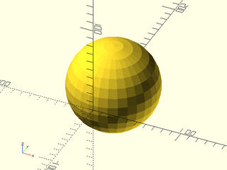
Example 1: By Radius
include <BOSL2/std.scad>
spheroid(r=50);
Example 2: By Diameter

include <BOSL2/std.scad>
spheroid(d=100);
Example 3: style="orig"
include <BOSL2/std.scad>
spheroid(d=100, style="orig", $fn=10);
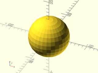
Example 4: style="aligned"
include <BOSL2/std.scad>
spheroid(d=100, style="aligned", $fn=10);
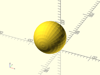
Example 5: style="stagger"
include <BOSL2/std.scad>
spheroid(d=100, style="stagger", $fn=10);
Example 6: style="stagger" with circum=true
include <BOSL2/std.scad>
spheroid(d=100, style="stagger", circum=true, $fn=10);
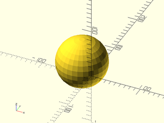
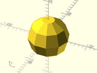
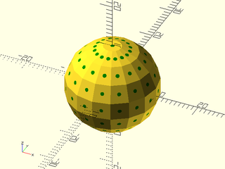
Example 7: style="octa", octahedral based tesselation. In this style, $fn is quantized to a multiple of 4.
include <BOSL2/std.scad>
spheroid(d=100, style="octa", $fn=10);
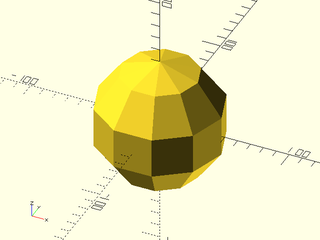
Example 8: style="octa", with circum=true, produces mostly very irregular hexagonal faces
include <BOSL2/std.scad>
spheroid(d=100, style="octa", circum=true, $fn=16);
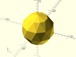
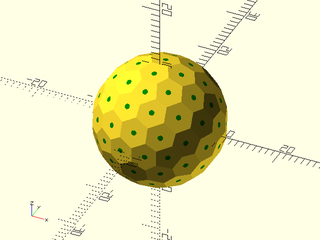
Example 9: style="icosa", icosahedral based tesselation. In this style, $fn is quantized to a multiple of 5.
include <BOSL2/std.scad>
spheroid(d=100, style="icosa", $fn=10);
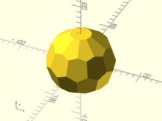
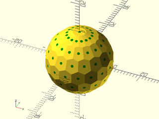
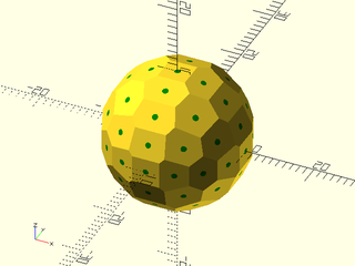
Example 10: style="icosa", circum=true. This style has hexagons and 12 pentagons, similar to (but not the same as) a soccer ball.
include <BOSL2/std.scad>
spheroid(d=100, style="icosa", circum=true, $fn=10);
Example 11: Anchoring
include <BOSL2/std.scad>
spheroid(d=100, anchor=FRONT);
Example 12: Spin

include <BOSL2/std.scad>
spheroid(d=100, anchor=FRONT, spin=45);
Example 13: Orientation

include <BOSL2/std.scad>
spheroid(d=100, anchor=FRONT, spin=45, orient=FWD);
Example 14: Standard Connectors
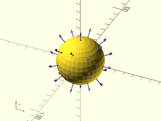
include <BOSL2/std.scad>
spheroid(d=50) show_anchors();
Example 15: Called as Function

include <BOSL2/std.scad>
vnf = spheroid(d=100, style="icosa");
vnf_polyhedron(vnf);
Example 16: With "orig" the circumscribing sphere has the same form. The green sphere is a tiny bit oversized so it pokes through the low points in the circumscribed sphere with low $fn. This demonstrates that these spheres are in fact circumscribing.
include <BOSL2/std.scad>
color("green")spheroid(r=10.01, $fn=256);
spheroid(r=10, style="orig", circum=true, $fn=16);
Example 17: With "aligned" the same is true: the circumscribing sphere is also aligned, if $fn is divisible by 4.

include <BOSL2/std.scad>
color("green")spheroid(r=10.01, $fn=256);
spheroid(r=10, style="aligned", circum=true, $fn=16);
Example 18: For the other styles, the circumscribing sphere is different, as shown here with "stagger"
include <BOSL2/std.scad>
color("green")spheroid(r=10.01, $fn=256);
spheroid(r=10, style="stagger", circum=true, $fn=16);
Example 19: The dual of "octa" that provides the circumscribing sphere has weird asymmetric hexagonal faces:
include <BOSL2/std.scad>
color("green")spheroid(r=10.01, $fn=256);
spheroid(r=10, style="octa", circum=true, $fn=16);
Example 20: The dual of "icosa" features hexagons and always 12 pentagons:
include <BOSL2/std.scad>
color("green")spheroid(r=10.01, $fn=256);
spheroid(r=10, style="icosa", circum=true, $fn=16);
Synopsis: Creates an attachable torus. [Geom] [VNF]
Topics: Shapes (3D), Attachable, VNF Generators
See Also: spheroid(), cyl()
Usage: As Module
- torus(r_maj|d_maj, r_min|d_min, [center], ...) [ATTACHMENTS];
- torus(or|od, ir|id, ...) [ATTACHMENTS];
- torus(r_maj|d_maj, or|od, ...) [ATTACHMENTS];
- torus(r_maj|d_maj, ir|id, ...) [ATTACHMENTS];
- torus(r_min|d_min, or|od, ...) [ATTACHMENTS];
- torus(r_min|d_min, ir|id, ...) [ATTACHMENTS];
Usage: As Function
- vnf = torus(r_maj|d_maj, r_min|d_min, [center], ...);
- vnf = torus(or|od, ir|id, ...);
- vnf = torus(r_maj|d_maj, or|od, ...);
- vnf = torus(r_maj|d_maj, ir|id, ...);
- vnf = torus(r_min|d_min, or|od, ...);
- vnf = torus(r_min|d_min, ir|id, ...);
Description:
Creates an attachable toroidal shape.
Figure 1:

Arguments:
| By Position | What it does |
|---|---|
r_maj |
major radius of torus ring. (use with 'r_min', or 'd_min') |
r_min |
minor radius of torus ring. (use with 'r_maj', or 'd_maj') |
center |
If given, overrides anchor. A true value sets anchor=CENTER, false sets anchor=DOWN. |
| By Name | What it does |
|---|---|
d_maj |
major diameter of torus ring. (use with 'r_min', or 'd_min') |
d_min |
minor diameter of torus ring. (use with 'r_maj', or 'd_maj') |
or |
outer radius of the torus. (use with 'ir', or 'id') |
ir |
inside radius of the torus. (use with 'or', or 'od') |
od |
outer diameter of the torus. (use with 'ir' or 'id') |
id |
inside diameter of the torus. (use with 'or' or 'od') |
anchor |
Translate so anchor point is at origin (0,0,0). See anchor. Default: CENTER
|
orient |
Vector to rotate top towards, after spin. See orient. Default: UP
|
Example 1:
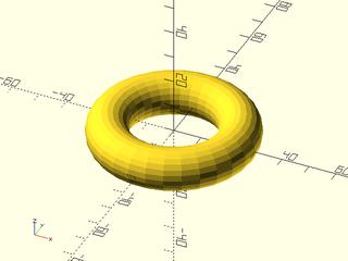
include <BOSL2/std.scad>
// These all produce the same torus.
torus(r_maj=22.5, r_min=7.5);
torus(d_maj=45, d_min=15);
torus(or=30, ir=15);
torus(od=60, id=30);
torus(d_maj=45, id=30);
torus(d_maj=45, od=60);
torus(d_min=15, id=30);
torus(d_min=15, od=60);
vnf_polyhedron(torus(d_min=15, od=60), convexity=4);
Example 2: Standard Connectors
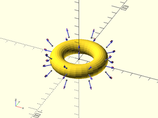
include <BOSL2/std.scad>
torus(od=60, id=30) show_anchors();
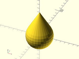
Synopsis: Creates a teardrop shape. [Geom] [VNF]
Topics: Shapes (3D), Attachable, VNF Generators, FDM Optimized
See Also: onion(), teardrop2d()
Usage: Typical
- teardrop(h|l=|length=|height=, r, [ang], [cap_h], [chamfer=], ...) [ATTACHMENTS];
- teardrop(h|l=|length=|height=, d=, [ang=], [cap_h=], [chamfer=], ...) [ATTACHMENTS];
Usage: Psuedo-Conical
- teardrop(h|l=|height=|length=, r1=, r2=, [ang=], [cap_h1=], [cap_h2=], ...) [ATTACHMENTS];
- teardrop(h|l=|height=|length=, d1=, d2=, [ang=], [cap_h1=], [cap_h2=], ...) [ATTACHMENTS];
Usage: As Function
- vnf = teardrop(h|l=|height=|length=, r|d=, [ang=], [cap_h=], ...);
- vnf = teardrop(h|l=|height=|length=, r1=|d1=, r2=|d2=, [ang=], [cap_h=], ...);
- vnf = teardrop(h|l=|height=|length=, r1=|d1=, r2=|d2=, [ang=], [cap_h1=], [cap_h2=], ...);
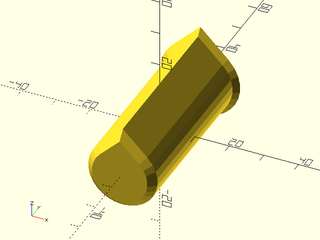
Description:
Makes a teardrop shape in the XZ plane. Useful for 3D printable holes. Optional chamfers can be added with positive or negative distances. A positive distance specifies the amount to inset the chamfer along the front/back faces of the shape. The chamfer will extend the same y distance into the shape. If the radii are the same then the chamfer will be a 45 degree chamfer, but in other cases it will not. Note that with caps, the chamfer must not be so big that it makes the cap height illegal.
Arguments:
| By Position | What it does |
|---|---|
h / l / height / length
|
Thickness of teardrop. Default: 1 |
r |
Radius of circular part of teardrop. Default: 1 |
ang |
Angle of hat walls from the Z axis. Default: 45 degrees |
cap_h |
If given, height above center where the shape will be truncated. Default: undef (no truncation) |
| By Name | What it does |
|---|---|
circum |
produce a circumscribing teardrop shape. Default: false |
r1 |
Radius of circular portion of the front end of the teardrop shape. |
r2 |
Radius of circular portion of the back end of the teardrop shape. |
d |
Diameter of circular portion of the teardrop shape. |
d1 |
Diameter of circular portion of the front end of the teardrop shape. |
d2 |
Diameter of circular portion of the back end of the teardrop shape. |
cap_h1 |
If given, height above center where the shape will be truncated, on the front side. Default: undef (no truncation) |
cap_h2 |
If given, height above center where the shape will be truncated, on the back side. Default: undef (no truncation) |
chamfer |
Specifies size of chamfer as distance along the bottom and top faces. Default: 0 |
chamfer1 |
Specifies size of chamfer on bottom as distance along bottom face. Default: 0 |
chamfer2 |
Specifies size of chamfer on top as distance along top face. Default: 0 |
realign |
Passes realign option to teardrop2d, which shifts face alignment. Default: false |
anchor |
Translate so anchor point is at origin (0,0,0). See anchor. Default: CENTER
|
spin |
Rotate this many degrees around the Z axis after anchor. See spin. Default: 0
|
orient |
Vector to rotate top towards, after spin. See orient. Default: UP
|
Extra Anchors:
| Anchor Name | Position |
|---|---|
| cap | The center of the top of the cap, oriented with the cap face normal. |
| cap_fwd | The front edge of the cap. |
| cap_back | The back edge of the cap. |
Example 1: Typical Shape
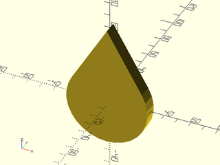
include <BOSL2/std.scad>
teardrop(r=30, h=10, ang=30);
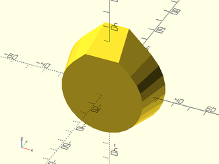
Example 2: Crop Cap
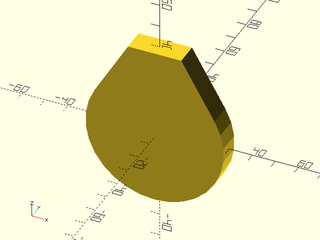
include <BOSL2/std.scad>
teardrop(r=30, h=10, ang=30, cap_h=40);
Example 3: Close Crop
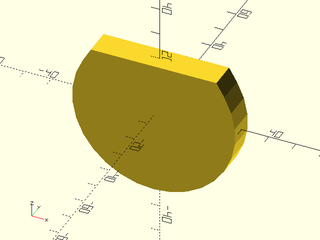
include <BOSL2/std.scad>
teardrop(r=30, h=10, ang=30, cap_h=20);
Example 4: Psuedo-Conical
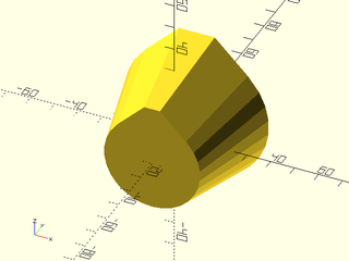
include <BOSL2/std.scad>
teardrop(r1=20, r2=30, h=40, cap_h1=25, cap_h2=35);
Example 5: Adding chamfers can be useful for a teardrop hole mask
include <BOSL2/std.scad>
teardrop(r=10, l=50, chamfer1=2, chamfer2=-1.5);
Example 6: Getting a VNF
include <BOSL2/std.scad>
vnf = teardrop(r1=25, r2=30, l=20, cap_h1=25, cap_h2=35);
vnf_polyhedron(vnf);
Example 7: Standard Conical Connectors
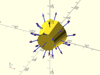
include <BOSL2/std.scad>
teardrop(d1=20, d2=30, h=20, cap_h1=11, cap_h2=16)
    show_anchors(custom=false);
Example 8: Named Conical Connectors
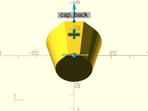
include <BOSL2/std.scad>
teardrop(d1=20, d2=30, h=20, cap_h1=11, cap_h2=16)
    show_anchors(std=false);
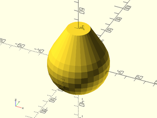
Synopsis: Creates an attachable onion-like shape. [Geom] [VNF]
Topics: Shapes (3D), Attachable, VNF Generators, FDM Optimized
See Also: teardrop(), teardrop2d()
Usage: As Module
- onion(r|d=, [ang=], [cap_h=], [circum=], [realign=], ...) [ATTACHMENTS];
Usage: As Function
- vnf = onion(r|d=, [ang=], [cap_h=], [circum=], [realign=], ...);
Description:
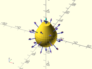
Creates a sphere with a conical hat, to make a 3D teardrop.
Arguments:
| By Position | What it does |
|---|---|
r |
radius of spherical portion of the bottom. Default: 1 |
ang |
Angle of cone on top from vertical. Default: 45 degrees |
cap_h |
If given, height above sphere center to truncate teardrop shape. Default: undef (no truncation) |
| By Name | What it does |
|---|---|
circum |
set to true to circumscribe the specified radius/diameter. Default: False |
realign |
adjust point alignment to determine if bottom is flat or pointy. Default: False |
d |
diameter of spherical portion of bottom. |
anchor |
Translate so anchor point is at origin (0,0,0). See anchor. Default: CENTER
|
spin |
Rotate this many degrees around the Z axis after anchor. See spin. Default: 0
|
orient |
Vector to rotate top towards, after spin. See orient. Default: UP
|
Extra Anchors:
| Anchor Name | Position |
|---|---|
| cap | The center of the top of the cap, oriented with the cap face normal. |
| tip | The position where an un-capped onion would come to a point, oriented in the direction the point is from the center. |
Example 1: Typical Shape
include <BOSL2/std.scad>
onion(r=30, ang=30);
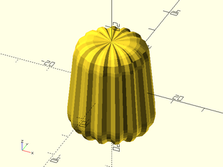
Example 2: Crop Cap
include <BOSL2/std.scad>
onion(r=30, ang=30, cap_h=40);
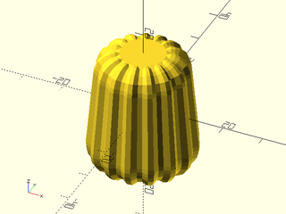
Example 3: Close Crop
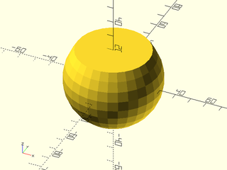
include <BOSL2/std.scad>
onion(r=30, ang=30, cap_h=20);
Example 4: Onions are useful for making the tops of large cylindrical voids.
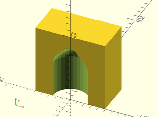
include <BOSL2/std.scad>
difference() {
    cuboid([100,50,100], anchor=FWD+BOT);
    down(0.1)
        cylinder(h=50,d=50,anchor=BOT)
            attach(TOP)
                onion(d=50, cap_h=30);
}
Example 5: Standard Connectors
include <BOSL2/std.scad>
onion(d=30, ang=30, cap_h=20) show_anchors();
Synopsis: Creates an attachable 3d text block. [Geom]
Topics: Attachments, Text
See Also: path_text(), text()
Usage:
- text3d(text, [h], [size], [font], [language=], [script=], [direction=], [atype=], [anchor=], [spin=], [orient=]);
Description:
Creates a 3D text block that supports anchoring and attachment to attachable objects. You cannot attach children to text.
Historically fonts were specified by their "body size", the height of the metal body on which the glyphs were cast. This means the size was an upper bound on the size of the font glyphs, not a direct measurement of their size. In digital typesetting, the metal body is replaced by an invisible box, the em square, whose side length is defined to be the font's size. The glyphs can be contained in that square, or they can extend beyond it, depending on the choices made by the font designer. As a result, the meaning of font size varies between fonts: two fonts at the "same" size can differ significantly in the actual size of their characters. Typographers customarily specify the size in the units of "points". A point is 1/72 inch. In OpenSCAD, you specify the size in OpenSCAD units (often treated as millimeters for 3d printing), so if you want points you will need to perform a suitable unit conversion. In addition, the OpenSCAD font system has a bug: if you specify size=s you will instead get a font whose size is s/0.72. For many fonts this means the size of capital letters will be approximately equal to s, because it is common for fonts to use about 70% of their height for the ascenders in the font. To get the customary font size, you should multiply your desired size by 0.72.
To find the fonts that you have available in your OpenSCAD installation, go to the Help menu and select "Font List".
Arguments:
| By Position | What it does |
|---|---|
text |
Text to create. |
h / height / thickness
|
Extrusion height for the text. Default: 1 |
size |
The font will be created at this size divided by 0.72. Default: 10 |
font |
Font to use. Default: "Liberation Sans" (standard OpenSCAD default) |
| By Name | What it does |
|---|---|
spacing |
The relative spacing multiplier between characters. Default: 1.0
|
direction |
The text direction. "ltr" for left to right. "rtl" for right to left. "ttb" for top to bottom. "btt" for bottom to top. Default: "ltr"
|
language |
The language the text is in. Default: "en"
|
script |
The script the text is in. Default: "latin"
|
atype |
Change vertical center between "baseline" and "ycenter". Default: "baseline" |
anchor |
Translate so anchor point is at origin (0,0,0). See anchor. Default: "baseline"
|
center |
Center the text. Equivalent to atype="center", anchor=CENTER. Default: false |
spin |
Rotate this many degrees around the Z axis. See spin. Default: 0
|
orient |
Vector to rotate top towards. See orient. Default: UP
|
Anchor Types:
| Anchor Type | What it is |
|---|---|
| baseline | Anchor center is relative to text baseline |
| ycenter | Anchor center is relative to the actualy y direction center of the text |
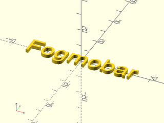
Example 1:
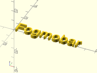
include <BOSL2/std.scad>
text3d("Fogmobar", h=3, size=10);
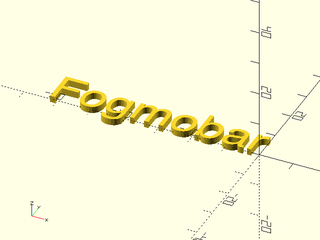
Example 2:
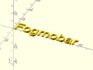
include <BOSL2/std.scad>
text3d("Fogmobar", h=2, size=12, font="Helvetica");
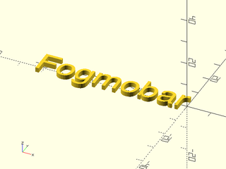
Example 3:
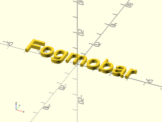
include <BOSL2/std.scad>
text3d("Fogmobar", h=2, anchor=CENTER);
Example 4:
include <BOSL2/std.scad>
text3d("Fogmobar", h=2, anchor=CENTER, atype="ycenter");
Example 5:
include <BOSL2/std.scad>
text3d("Fogmobar", h=2, anchor=RIGHT);
Example 6:
include <BOSL2/std.scad>
text3d("Fogmobar", h=2, anchor=RIGHT+BOT, atype="ycenter");
Synopsis: Creates 2d or 3d text placed along a path. [Geom]
Topics: Text, Paths, Paths (2D), Paths (3D), Path Generators, Path Generators (2D)
Usage:
- path_text(path, text, [size], [thickness], [font], [lettersize=], [offset=], [reverse=], [normal=], [top=], [textmetrics=], [kern=])
Description:
Place the text letter by letter onto the specified path using textmetrics (if available and requested) or user specified letter spacing. The path can be 2D or 3D. In 2D the text appears along the path with letters upright as determined by the path direction. In 3D by default letters are positioned on the tangent line to the path with the path normal pointing toward the reader. The path normal points away from the center of curvature (the opposite of the normal produced by path_normals()). Note that this means that if the center of curvature switches sides the text will flip upside down. If you want text on such a path you must supply your own normal or top vector.
Text appears starting at the beginning of the path, so if the 3D path moves right to left then a left-to-right reading language will display in the wrong order. (For a 2D path text will appear upside down.) The text for a 3D path appears positioned to be read from "outside" of the curve (from a point on the other side of the curve from the center of curvature). If you need the text to read properly from the inside, you can set reverse to true to flip the text, or supply your own normal.
If you do not have the experimental textmetrics feature enabled then you must specify the space for the letters using lettersize, which can be a scalar or array. You will have the easiest time getting good results by using a monospace font such as Courier. Note that even with text metrics, spacing may be different because path_text() doesn't do kerning to adjust positions of individual glyphs. Also if your font has ligatures they won't be used.
By default letters appear centered on the path. The offset can be specified to shift letters toward the reader (in the direction of the normal).
You can specify your own normal by setting normal to a direction or a list of directions. Your normal vector should
point toward the reader. You can also specify
top, which directs the top of the letters in a desired direction. If you specify your own directions and they
are not perpendicular to the path then the direction you specify will take priority and the
letters will not rest on the tangent line of the path. Note that the normal or top directions that you
specify must not be parallel to the path.
Historically fonts were specified by their "body size", the height of the metal body on which the glyphs were cast. This means the size was an upper bound on the size of the font glyphs, not a direct measurement of their size. In digital typesetting, the metal body is replaced by an invisible box, the em square, whose side length is defined to be the font's size. The glyphs can be contained in that square, or they can extend beyond it, depending on the choices made by the font designer. As a result, the meaning of font size varies between fonts: two fonts at the "same" size can differ significantly in the actual size of their characters. Typographers customarily specify the size in the units of "points". A point is 1/72 inch. In OpenSCAD, you specify the size in OpenSCAD units (often treated as millimeters for 3d printing), so if you want points you will need to perform a suitable unit conversion. In addition, the OpenSCAD font system has a bug: if you specify size=s you will instead get a font whose size is s/0.72. For many fonts this means the size of capital letters will be approximately equal to s, because it is common for fonts to use about 70% of their height for the ascenders in the font. To get the customary font size, you should multiply your desired size by 0.72.
To find the fonts that you have available in your OpenSCAD installation, go to the Help menu and select "Font List".
Arguments:
| By Position | What it does |
|---|---|
path |
path to place the text on |
text |
text to create |
size |
The font will be created at this size divided by 0.72. |
thickness / h / height
|
thickness of letters (not allowed for 2D path) |
font |
font to use. Default: "Liberation Sans" |
| By Name | What it does |
|---|---|
lettersize |
scalar or array giving size of letters |
center |
center text on the path instead of starting at the first point. Default: false |
offset |
distance to shift letters "up" (towards the reader). Not allowed for 2D path. Default: 0 |
normal |
direction or list of directions pointing towards the reader of the text. Not allowed for 2D path. |
top |
direction or list of directions pointing toward the top of the text |
reverse |
reverse the letters if true. Not allowed for 2D path. Default: false |
textmetrics |
if set to true and lettersize is not given then use the experimental textmetrics feature. You must be running a dev snapshot that includes this feature and have the feature turned on in your preferences. Default: false |
valign |
align text to the path using "top", "bottom", "center" or "baseline". You can also adjust position with a numerical offset as in "top-5" or "bottom+2". This only works with textmetrics enabled. You can give a simple numerical offset, which will be relative to the baseline and works even without textmetrics. Default: "baseline" |
kern |
scalar or array giving spacing adjusments between each letter. If it's an array it should have one less entry than the text string. Default: 0 |
language |
text language, passed to OpenSCAD text(). Default: "en" |
script |
text script, passed to OpenSCAD text(). Default: "latin" |
Example 1: The examples use Courier, a monospaced font. The width is 1/1.2 times the specified size for this font. This text could wrap around a cylinder.
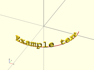
include <BOSL2/std.scad>
path = path3d(arc(100, r=25, angle=[245, 370]));
color("red")stroke(path, width=.3);
path_text(path, "Example text", font="Courier", size=5, lettersize = 5/1.2);
Example 2: By setting the normal to UP we can get text that lies flat, for writing around the edge of a disk:
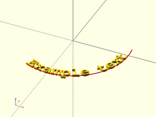
include <BOSL2/std.scad>
path = path3d(arc(100, r=25, angle=[245, 370]));
color("red")stroke(path, width=.3);
path_text(path, "Example text", font="Courier", size=5, lettersize = 5/1.2, normal=UP);
Example 3: If we want text that reads from the other side we can use reverse. Note we have to reverse the direction of the path and also set the reverse option.
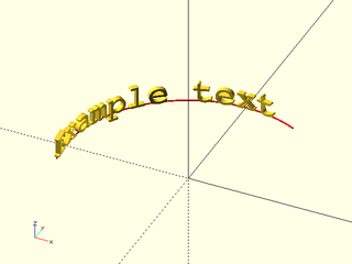
include <BOSL2/std.scad>
path = reverse(path3d(arc(100, r=25, angle=[65, 190])));
color("red")stroke(path, width=.3);
path_text(path, "Example text", font="Courier", size=5, lettersize = 5/1.2, reverse=true);
Example 4: text debossed onto a cylinder in a spiral. The text is 1 unit deep because it is half in, half out.
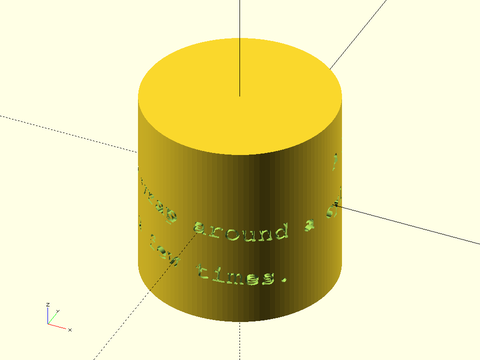
include <BOSL2/std.scad>
text = ("A long text example to wrap around a cylinder, possibly for a few times.");
L = 5*len(text);
maxang = 360*L/(PI*50);
spiral = [for(a=[0:1:maxang]) [25*cos(a), 25*sin(a), 10-30/maxang*a]];
difference(){
  cyl(d=50, l=50, $fn=120);
  path_text(spiral, text, size=5, lettersize=5/1.2, font="Courier", thickness=2);
}
Example 5: Same example but text embossed. Make sure you have enough depth for the letters to fully overlap the object.
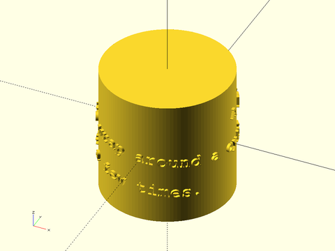
include <BOSL2/std.scad>
text = ("A long text example to wrap around a cylinder, possibly for a few times.");
L = 5*len(text);
maxang = 360*L/(PI*50);
spiral = [for(a=[0:1:maxang]) [25*cos(a), 25*sin(a), 10-30/maxang*a]];
cyl(d=50, l=50, $fn=120);
path_text(spiral, text, size=5, lettersize=5/1.2, font="Courier", thickness=2);
Example 6: Here the text baseline sits on the path. (Note the default orientation makes text readable from below, so we specify the normal.)
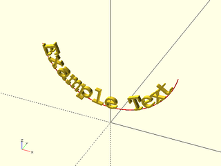
include <BOSL2/std.scad>
path = arc(100, points = [[-20, 0, 20], [0,0,5], [20,0,20]]);
color("red")stroke(path,width=.2);
path_text(path, "Example Text", size=5, lettersize=5/1.2, font="Courier", normal=FRONT);
Example 7: If we use top to orient the text upward, the text baseline is no longer aligned with the path.
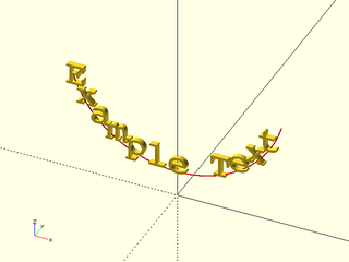
include <BOSL2/std.scad>
path = arc(100, points = [[-20, 0, 20], [0,0,5], [20,0,20]]);
color("red")stroke(path,width=.2);
path_text(path, "Example Text", size=5, lettersize=5/1.2, font="Courier", top=UP);
Example 8: This sine wave wrapped around the cylinder has a twisting normal that produces wild letter layout. We fix it with a custom normal which is different at every path point.
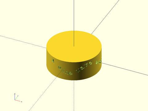
include <BOSL2/std.scad>
path = [for(theta = [0:360]) [25*cos(theta), 25*sin(theta), 4*cos(theta*4)]];
normal = [for(theta = [0:360]) [cos(theta), sin(theta),0]];
zrot(-120)
difference(){
  cyl(r=25, h=20, $fn=120);
  path_text(path, "A sine wave wiggles", font="Courier", lettersize=5/1.2, size=5, normal=normal);
}
Example 9: The path center of curvature changes, and the text flips.
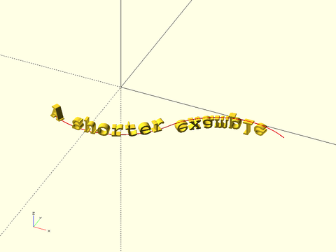
include <BOSL2/std.scad>
path =  zrot(-120,p=path3d( concat(arc(100, r=25, angle=[0,90]), back(50,p=arc(100, r=25, angle=[268, 180])))));
color("red")stroke(path,width=.2);
path_text(path, "A shorter example",  size=5, lettersize=5/1.2, font="Courier", thickness=2);
Example 10: We can fix it with top:
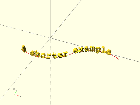
include <BOSL2/std.scad>
path =  zrot(-120,p=path3d( concat(arc(100, r=25, angle=[0,90]), back(50,p=arc(100, r=25, angle=[268, 180])))));
color("red")stroke(path,width=.2);
path_text(path, "A shorter example",  size=5, lettersize=5/1.2, font="Courier", thickness=2, top=UP);
Example 11: With a 2D path instead of 3D there's no ambiguity about direction and it works by default:
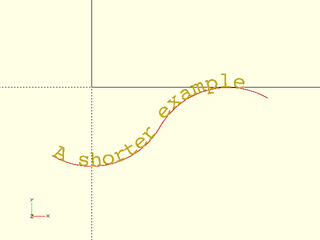
include <BOSL2/std.scad>
path =  zrot(-120,p=concat(arc(100, r=25, angle=[0,90]), back(50,p=arc(100, r=25, angle=[268, 180]))));
color("red")stroke(path,width=.2);
path_text(path, "A shorter example",  size=5, lettersize=5/1.2, font="Courier");
Example 12: The kern parameter lets you adjust the letter spacing either with a uniform value for each letter, or with an array to make adjustments throughout the text. Here we show a case where adding some extra space gives a better look in a tight circle. When textmetrics are off, lettersize can do this job, but with textmetrics, you'll need to use kern to make adjustments relative to the text metric sizes.
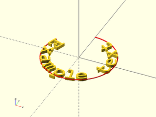
include <BOSL2/std.scad>
path = path3d(arc(100, r=12, angle=[150, 450]));
color("red")stroke(path, width=.3);
kern = [1,1.2,1,1,.3,-.2,1,0,.8,1,1.1];
path_text(path, "Example text", font="Courier", size=5, lettersize = 5/1.2, kern=kern, normal=UP);
Synopsis: Creates a smooth fillet between two faces. [Geom] [VNF]
Topics: Shapes (3D), Attachable
See Also: mask2d_roundover()
Usage: Typical
- fillet(l, r, [ang], [overlap], ...) [ATTACHMENTS];
- fillet(l|length=|h=|height=, d=, [ang=], [overlap=], ...) [ATTACHMENTS];
Description:
Creates a shape that can be unioned into a concave joint between two faces, to fillet them. Center this part along the concave edge to be chamfered and union it in.
Arguments:
| By Position | What it does |
|---|---|
l / length / h / height
|
Length of edge to fillet. |
r |
Radius of fillet. |
ang |
Angle between faces to fillet. |
overlap |
Overlap size for unioning with faces. |
| By Name | What it does |
|---|---|
d |
Diameter of fillet. |
anchor |
Translate so anchor point is at origin (0,0,0). See anchor. Default: FRONT+LEFT
|
spin |
Rotate this many degrees around the Z axis after anchor. See spin. Default: 0
|
orient |
Vector to rotate top towards, after spin. See orient. Default: UP
|
Example 1:
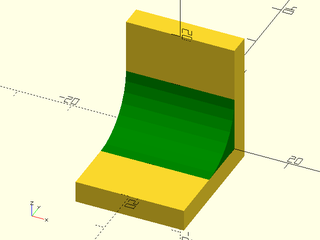
include <BOSL2/std.scad>
union() {
  translate([0,2,-4])
    cube([20, 4, 24], anchor=BOTTOM);
  translate([0,-10,-4])
    cube([20, 20, 4], anchor=BOTTOM);
  color("green")
    fillet(
      l=20, r=10,
      spin=180, orient=RIGHT
    );
}
Example 2:
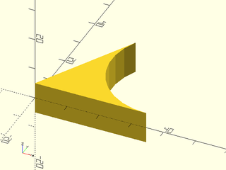
include <BOSL2/std.scad>
fillet(l=10, r=20, ang=60);
Example 3:
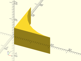
include <BOSL2/std.scad>
fillet(l=10, r=20, ang=90);
Example 4:
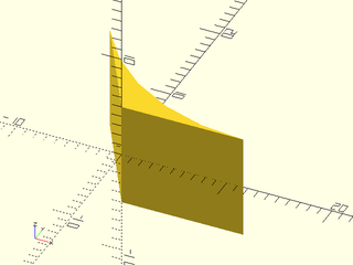
include <BOSL2/std.scad>
fillet(l=10, r=20, ang=120);
Example 5: Using with Attachments
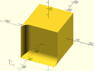
include <BOSL2/std.scad>
cube(50,center=true) {
  position(FRONT+LEFT)
    fillet(l=50, r=10, spin=-90);
  position(BOT+FRONT)
    fillet(l=50, r=10, spin=180, orient=RIGHT);
}
Synopsis: Generates a 3D surface from a 2D grid of values. [Geom] [VNF]
Topics: Textures, Heightfield
See Also: cylindrical_heightfield()
Usage: As Module
- heightfield(data, [size], [bottom], [maxz], [xrange], [yrange], [style], [convexity], ...) [ATTACHMENTS];
Usage: As Function
- vnf = heightfield(data, [size], [bottom], [maxz], [xrange], [yrange], [style], ...);
Description:
Given a regular rectangular 2D grid of scalar values, or a function literal, generates a 3D surface where the height at any given point is the scalar value for that position. One script to convert a grayscale image to a heightfield array in a .scad file can be found at: https://raw.githubusercontent.com/BelfrySCAD/BOSL2/master/scripts/img2scad.py
Arguments:
| By Position | What it does |
|---|---|
data |
This is either the 2D rectangular array of heights, or a function literal that takes X and Y arguments. |
size |
The [X,Y] size of the surface to create. If given as a scalar, use it for both X and Y sizes. Default: [100,100]
|
bottom |
The Z coordinate for the bottom of the heightfield object to create. Any heights lower than this will be truncated to very slightly above this height. Default: -20 |
maxz |
The maximum height to model. Truncates anything taller to this height. Set to INF for no truncation. Default: 100 |
xrange |
A range of values to iterate X over when calculating a surface from a function literal. Default: [-1 : 0.01 : 1] |
yrange |
A range of values to iterate Y over when calculating a surface from a function literal. Default: [-1 : 0.01 : 1] |
style |
The style of subdividing the quads into faces. Valid options are "default", "alt", and "quincunx". Default: "default" |
| By Name | What it does |
|---|---|
convexity |
Max number of times a line could intersect a wall of the surface being formed. Module only. Default: 10 |
anchor |
Translate so anchor point is at origin (0,0,0). See anchor. Default: CENTER
|
spin |
Rotate this many degrees around the Z axis. See spin. Default: 0
|
orient |
Vector to rotate top towards. See orient. Default: UP
|
Example 1:
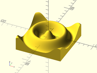
include <BOSL2/std.scad>
heightfield(size=[100,100], bottom=-20, data=[
    for (y=[-180:4:180]) [
        for(x=[-180:4:180])
        10*cos(3*norm([x,y]))
    ]
]);
Example 2:
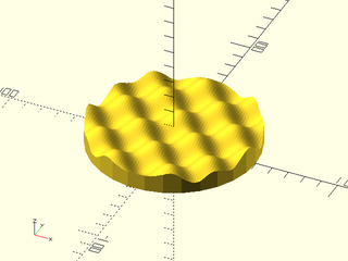
include <BOSL2/std.scad>
intersection() {
    heightfield(size=[100,100], data=[
        for (y=[-180:5:180]) [
            for(x=[-180:5:180])
            10+5*cos(3*x)*sin(3*y)
        ]
    ]);
    cylinder(h=50,d=100);
}
Example 3: Heightfield by Function
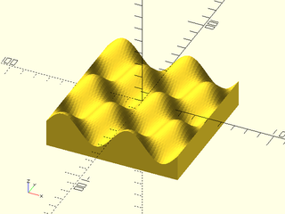
include <BOSL2/std.scad>
fn = function (x,y) 10*sin(x*360)*cos(y*360);
heightfield(size=[100,100], data=fn);
Example 4: Heightfield by Function, with Specific Ranges
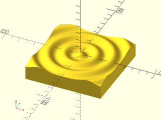
include <BOSL2/std.scad>
fn = function (x,y) 2*cos(5*norm([x,y]));
heightfield(
    size=[100,100], bottom=-20, data=fn,
    xrange=[-180:2:180], yrange=[-180:2:180]
);
Synopsis: Generates a cylindrical 3d surface from a 2D grid of values. [Geom] [VNF]
Topics: Extrusion, Textures, Knurling, Heightfield
See Also: heightfield()
Usage: As Function
- vnf = cylindrical_heightfield(data, l|length=|h=|height=, r|d=, [base=], [transpose=], [aspect=]);
Usage: As Module
- cylindrical_heightfield(data, l|length=|h=|height=, r|d=, [base=], [transpose=], [aspect=]) [ATTACHMENTS];
Description:
Given a regular rectangular 2D grid of scalar values, or a function literal of signature (x,y), generates
a cylindrical 3D surface where the height at any given point above the radius r=, is the scalar value
for that position.
One script to convert a grayscale image to a heightfield array in a .scad file can be found at:
https://raw.githubusercontent.com/BelfrySCAD/BOSL2/master/scripts/img2scad.py
Arguments:
| By Position | What it does |
|---|---|
data |
This is either the 2D rectangular array of heights, or a function literal of signature (x, y). |
l / length / h / height
|
The length of the cylinder to wrap around. |
r |
The radius of the cylinder to wrap around. |
| By Name | What it does |
|---|---|
r1 |
The radius of the bottom of the cylinder to wrap around. |
r2 |
The radius of the top of the cylinder to wrap around. |
d |
The diameter of the cylinder to wrap around. |
d1 |
The diameter of the bottom of the cylinder to wrap around. |
d2 |
The diameter of the top of the cylinder to wrap around. |
base |
The radius for the bottom of the heightfield object to create. Any heights smaller than this will be truncated to very slightly above this height. Default: -20 |
transpose |
If true, swaps the radial and length axes of the data. Default: false |
aspect |
The aspect ratio of the generated heightfield at the surface of the cylinder. Default: 1 |
xrange |
A range of values to iterate X over when calculating a surface from a function literal. Default: [-1 : 0.01 : 1] |
yrange |
A range of values to iterate Y over when calculating a surface from a function literal. Default: [-1 : 0.01 : 1] |
maxh |
The maximum height above the radius to model. Truncates anything taller to this height. Default: 99 |
style |
The style of subdividing the quads into faces. Valid options are "default", "alt", and "quincunx". Default: "default" |
convexity |
Max number of times a line could intersect a wall of the surface being formed. Module only. Default: 10 |
anchor |
Translate so anchor point is at origin (0,0,0). See anchor. Default: CENTER
|
spin |
Rotate this many degrees around the Z axis. See spin. Default: 0
|
orient |
Vector to rotate top towards. See orient. Default: UP
|
Example 1:
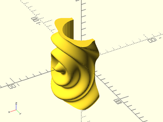
include <BOSL2/std.scad>
cylindrical_heightfield(l=100, r=30, base=5, data=[
    for (y=[-180:4:180]) [
        for(x=[-180:4:180])
        5*cos(5*norm([x,y]))+5
    ]
]);
Example 2:
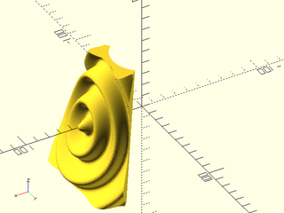
include <BOSL2/std.scad>
cylindrical_heightfield(l=100, r1=60, r2=30, base=5, data=[
    for (y=[-180:4:180]) [
        for(x=[-180:4:180])
        5*cos(5*norm([x,y]))+5
    ]
]);
Example 3: Heightfield by Function
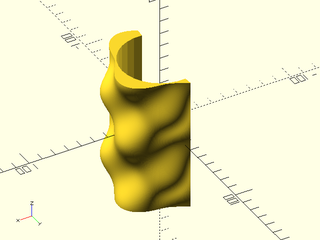
include <BOSL2/std.scad>
fn = function (x,y) 5*sin(x*360)*cos(y*360)+5;
cylindrical_heightfield(l=100, r=30, data=fn);
Example 4: Heightfield by Function, with Specific Ranges
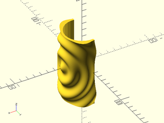
include <BOSL2/std.scad>
fn = function (x,y) 2*cos(5*norm([x,y]));
cylindrical_heightfield(
    l=100, r=30, base=5, data=fn,
    xrange=[-180:2:180], yrange=[-180:2:180]
);
Synopsis: Creates a ruler. [Geom]
Topics: Distance
Usage:
- ruler(length, width, [thickness=], [depth=], [labels=], [pipscale=], [maxscale=], [colors=], [alpha=], [unit=], [inch=]) [ATTACHMENTS];
Description:
Creates an attachable ruler for checking dimensions of the model.
Arguments:
| By Position | What it does |
|---|---|
length |
length of the ruler. Default 100 |
width |
width of the ruler. Default: size of the largest unit division |
| By Name | What it does |
|---|---|
thickness |
thickness of the ruler. Default: 1 |
depth |
the depth of mark subdivisions. Default: 3 |
labels |
draw numeric labels for depths where labels are larger than 1. Default: false |
pipscale |
width scale of the pips relative to the next size up. Default: 1/3 |
maxscale |
log10 of the maximum width divisions to display. Default: based on input length |
colors |
colors to use for the ruler, a list of two values. Default: ["black","white"]
|
alpha |
transparency value. Default: 1.0 |
unit |
unit to mark. Scales the ruler marks to a different length. Default: 1 |
inch |
set to true for a ruler scaled to inches (assuming base dimension is mm). Default: false |
anchor |
Translate so anchor point is at origin (0,0,0). See anchor. Default: LEFT+BACK+TOP
|
spin |
Rotate this many degrees around the Z axis. See spin. Default: 0
|
orient |
Vector to rotate top towards. See orient. Default: UP
|
Example 1:
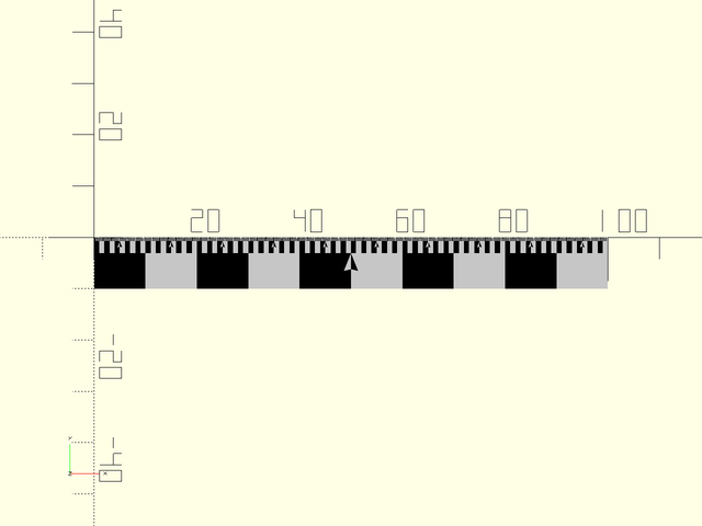
include <BOSL2/std.scad>
ruler(100,depth=3);
Example 2:
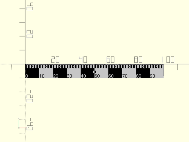
include <BOSL2/std.scad>
ruler(100,depth=3,labels=true);
Example 3:
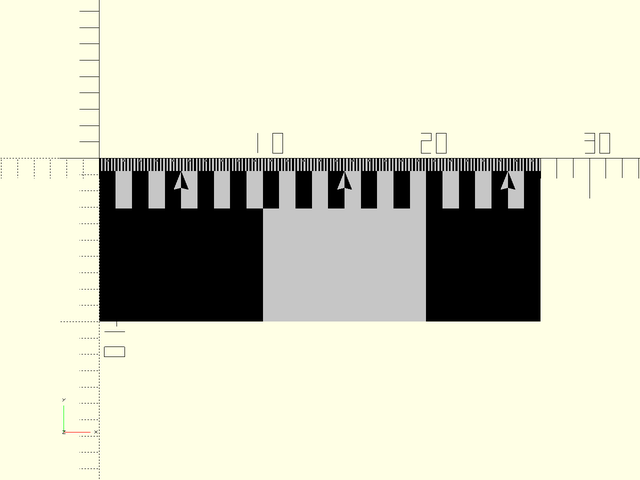
include <BOSL2/std.scad>
ruler(27);
Example 4:
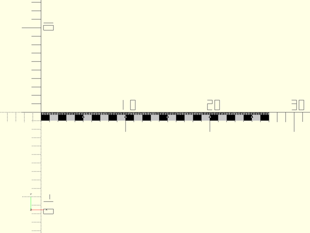
include <BOSL2/std.scad>
ruler(27,maxscale=0);
Example 5:

include <BOSL2/std.scad>
ruler(100,pipscale=3/4,depth=2);
Example 6:
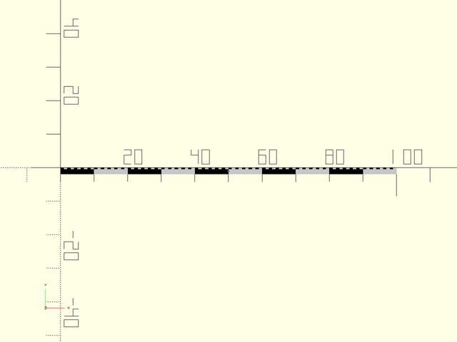
include <BOSL2/std.scad>
ruler(100,width=2,depth=2);
Example 7: Metric vs Imperial
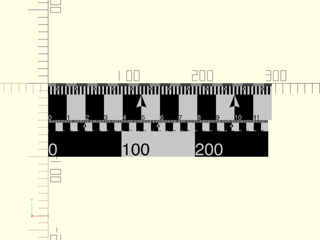
include <BOSL2/std.scad>
ruler(12,width=50,inch=true,labels=true,maxscale=0);
fwd(50)ruler(300,width=50,labels=true);