Tutorial Transforms
The translate() command is very simple:
include <BOSL2/std.scad>
#sphere(d=20);
translate([0,0,30]) sphere(d=20);
But at a glance, or when the formula to calculate the move is complex, it can be difficult to see
just what axis is being moved along, and in which direction. It's also a bit verbose for such a
frequently used command. For these reasons, BOSL2 provides you with shortcuts for each direction.
These shortcuts are up(), down(), fwd(), back(), left(), and right():
include <BOSL2/std.scad>
#sphere(d=20);
up(30) sphere(d=20);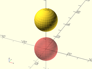
include <BOSL2/std.scad>
#sphere(d=20);
down(30) sphere(d=20);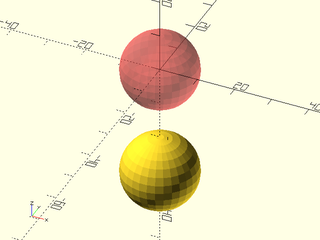
include <BOSL2/std.scad>
#sphere(d=20);
fwd(30) sphere(d=20);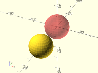
include <BOSL2/std.scad>
#sphere(d=20);
back(30) sphere(d=20);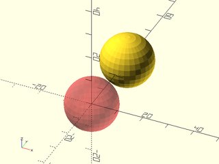
include <BOSL2/std.scad>
#sphere(d=20);
left(30) sphere(d=20);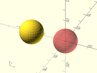
include <BOSL2/std.scad>
#sphere(d=20);
right(30) sphere(d=20);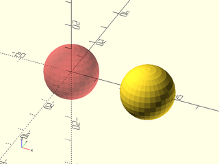
There is also a more generic move() command that can work just like translate():
include <BOSL2/std.scad>
#sphere(d=20);
move([30,-10]) sphere(d=20);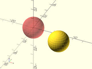
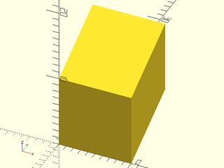
The scale() command is also fairly simple:
include <BOSL2/std.scad>
scale(2) cube(10, center=true);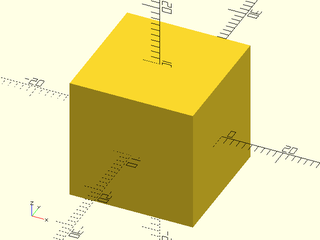
include <BOSL2/std.scad>
scale([1,2,3]) cube(10, center=true);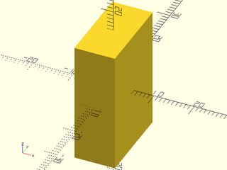
If you want to only change the scaling on one axis, though, BOSL2 provides clearer
commands to do just that; xscale(), yscale(), and zscale():
include <BOSL2/std.scad>
xscale(2) cube(10, center=true);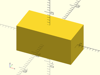
include <BOSL2/std.scad>
yscale(2) cube(10, center=true);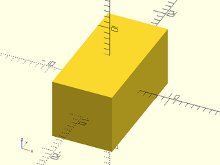
include <BOSL2/std.scad>
zscale(2) cube(10, center=true);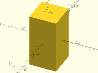
The rotate() command is fairly straightforward:
include <BOSL2/std.scad>
rotate([0,30,0]) cube(20, center=true);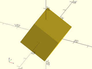
It is also a bit verbose, and can, at a glance, be difficult to tell just how it is rotating.
BOSL2 provides shortcuts for rotating around each axis, for clarity; xrot(), yrot(), and zrot():
include <BOSL2/std.scad>
xrot(30) cube(20, center=true);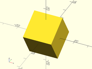
include <BOSL2/std.scad>
yrot(30) cube(20, center=true);
include <BOSL2/std.scad>
zrot(30) cube(20, center=true);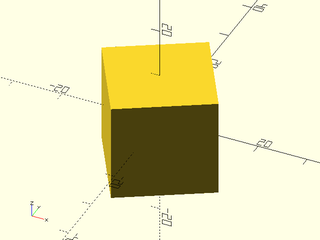
The rot() command is a more generic rotation command, and shorter to type than rotate():
include <BOSL2/std.scad>
rot([0,30,15]) cube(20, center=true);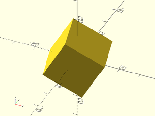
All of the rotation shortcuts can take a cp= argument, that lets you specify a
centerpoint to rotate around:
include <BOSL2/std.scad>
cp = [0,0,40];
color("blue") move(cp) sphere(d=3);
#cube(20, center=true);
xrot(45, cp=cp) cube(20, center=true);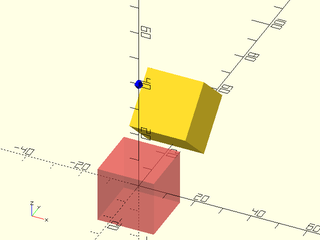
include <BOSL2/std.scad>
cp = [0,0,40];
color("blue") move(cp) sphere(d=3);
#cube(20, center=true);
yrot(45, cp=cp) cube(20, center=true);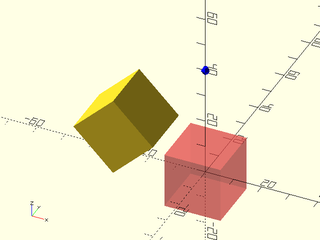
include <BOSL2/std.scad>
cp = [0,40,0];
color("blue") move(cp) sphere(d=3);
#cube(20, center=true);
zrot(45, cp=cp) cube(20, center=true);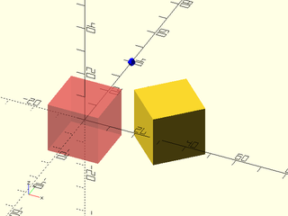
You can also do a new trick with it. You can rotate from pointing in one direction, towards another. You give these directions using vectors:
include <BOSL2/std.scad>
#cylinder(d=10, h=50);
rot(from=[0,0,1], to=[1,0,1]) cylinder(d=10, h=50);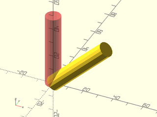
There are several direction vectors constants and aliases you can use for clarity:
| Constant | Value | Direction |
|---|---|---|
CENTER, CTR
|
[ 0, 0, 0] |
Centered |
LEFT |
[-1, 0, 0] |
Towards X- |
RIGHT |
[ 1, 0, 0] |
Towards X+ |
FWD, FORWARD, FRONT
|
[ 0,-1, 0] |
Towards Y- |
BACK |
[ 0, 1, 0] |
Towards Y+ |
DOWN, BOTTOM, BOT
|
[ 0, 0,-1] |
Towards Z- |
UP, TOP
|
[ 0, 0, 1] |
Towards Z+ |
This lets you rewrite the above vector rotation more clearly as:
include <BOSL2/std.scad>
#cylinder(d=10, h=50);
rot(from=UP, to=UP+RIGHT) cylinder(d=10, h=50);
The standard mirror() command works like this:
include <BOSL2/std.scad>
#yrot(60) cylinder(h=50, d1=20, d2=10);
mirror([1,0,0]) yrot(60) cylinder(h=50, d1=20, d2=10);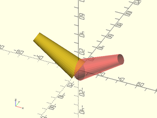
BOSL2 provides shortcuts for mirroring across the standard axes; xflip(), yflip(), and zflip():
include <BOSL2/std.scad>
#yrot(60) cylinder(h=50, d1=20, d2=10);
xflip() yrot(60) cylinder(h=50, d1=20, d2=10);
include <BOSL2/std.scad>
#xrot(60) cylinder(h=50, d1=20, d2=10);
yflip() xrot(60) cylinder(h=50, d1=20, d2=10);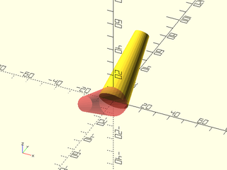
include <BOSL2/std.scad>
#cylinder(h=50, d1=20, d2=10);
zflip() cylinder(h=50, d1=20, d2=10);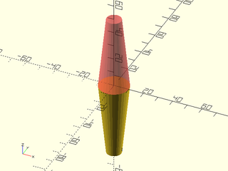
All of the flip commands can offset where the mirroring is performed:
include <BOSL2/std.scad>
#zrot(30) cube(20, center=true);
xflip(x=-20) zrot(30) cube(20, center=true);
color("blue",0.25) left(20) cube([0.1,50,50], center=true);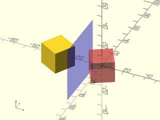
include <BOSL2/std.scad>
#zrot(30) cube(20, center=true);
yflip(y=20) zrot(30) cube(20, center=true);
color("blue",0.25) back(20) cube([40,0.1,40], center=true);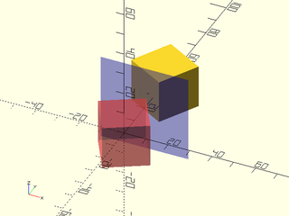
include <BOSL2/std.scad>
#xrot(30) cube(20, center=true);
zflip(z=-20) xrot(30) cube(20, center=true);
color("blue",0.25) down(20) cube([40,40,0.1], center=true);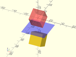
One transform that OpenSCAD does not perform natively is skewing.
BOSL2 provides the skew() command for that. You give it multipliers
for the skews you want to perform. The arguments used all start with s,
followed by the axis you want to skew along, followed by the axis that
the skewing will increase along. For example, to skew along the X axis as
you get farther along the Y axis, use the sxy= argument. If you give it
a multiplier of 0.5, then for each unit further along the Y axis you get,
you will add 0.5 units of skew to the X axis. Giving a negative multiplier
reverses the direction it skews:
include <BOSL2/std.scad>
skew(sxy=0.5) cube(10,center=false);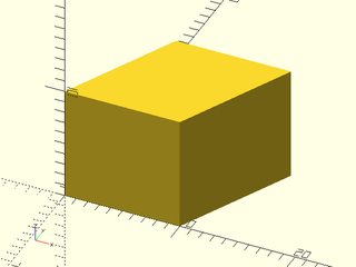
include <BOSL2/std.scad>
skew(sxz=-0.5) cube(10,center=false);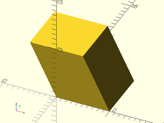
include <BOSL2/std.scad>
skew(syx=-0.5) cube(10,center=false);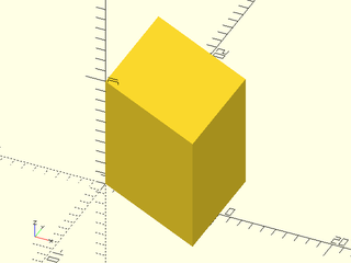
include <BOSL2/std.scad>
skew(syz=0.5) cube(10,center=false);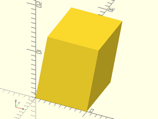
include <BOSL2/std.scad>
skew(szx=-0.5) cube(10,center=false);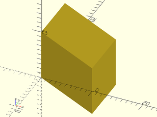
include <BOSL2/std.scad>
skew(szy=0.5) cube(10,center=false);