Tutorial Attachments
BOSL2 introduces the concept of attachables. You can do the following things with attachable shapes:
- Control where the shape appears and how it is oriented by anchoring and specifying orientation and spin
- Position or attach shapes relative to parent objects
- Tag objects and then control boolean operations based on their tags.
- Change the color of objects so that child objects are different colors than their parents
The various attachment features may seem complex at first, but attachability is one of the most important features of the BOSL2 library. It enables you to position objects relative to other objects in your model instead of having to keep track of absolute positions. It makes models simpler, more intuitive, and easier to maintain.
Almost all objects defined by BOSL2 are attachable. In addition,
BOSL2 overrides the built-in definitions for cube(), cylinder(),
sphere(), square(), circle() and text() and makes them attachable as
well. However, some basic OpenSCAD built-in definitions are not
attachable and will not work with the features described in this
tutorial. The non-attachables are polyhedron(), linear_extrude(),
rotate_extrude(), surface(), projection() and polygon().
Some of these have attachable alternatives: vnf_polyhedron(),
linear_sweep(), rotate_sweep(), and region().
Anchoring allows you to align a specified part of an object or point
on an object with the origin. The alignment point can be the center
of a side, the center of an edge, a corner, or some other
distinguished point on the object. This is done by passing a vector
or text string into the anchor= argument. For roughly cubical
or prismoidal shapes, that vector points in the general direction of the side, edge, or
corner that will be aligned to. For example, a vector of [1,0,-1] refers to the lower-right
edge of the shape. Each vector component should be -1, 0, or 1:
include <BOSL2/std.scad>
// Anchor at upper-front-left corner
cube([40,30,50], anchor=[-1,-1,1]);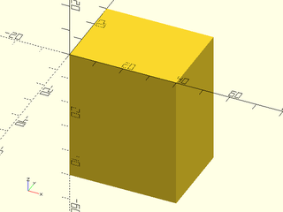
include <BOSL2/std.scad>
// Anchor at upper-right edge
cube([40,30,50], anchor=[1,0,1]);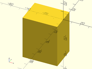
include <BOSL2/std.scad>
// Anchor at bottom face
cube([40,30,50], anchor=[0,0,-1]);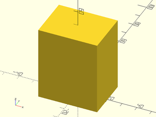
Since manually written vectors are not very intuitive, BOSL2 defines some standard directional vector constants that can be added together:
| Constant | Direction | Value |
|---|---|---|
LEFT |
X- | [-1, 0, 0] |
RIGHT |
X+ | [ 1, 0, 0] |
FRONT/FORWARD/FWD
|
Y− | [ 0, −1, 0] |
BACK |
Y+ | [ 0, 1, 0] |
BOTTOM/BOT/DOWN
|
Z− (Y− in 2D) |
[ 0, 0, −1] ([0, −1] in 2D.) |
TOP/UP
|
Z+ (Y+ in 2D) |
[ 0, 0, 1] ([0, 1] in 2D.) |
CENTER/CTR
|
Centered | [ 0, 0, 0] |
If you want a vector pointing towards the bottom−left edge, just add the BOTTOM and LEFT vector
constants together like BOTTOM + LEFT. This will result in a vector of [−1,0,−1]. You can pass
that to the anchor= argument for a clearly understandable anchoring:
include <BOSL2/std.scad>
cube([40,30,50], anchor=BACK+TOP);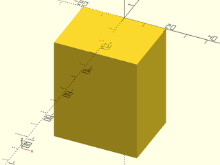
include <BOSL2/std.scad>
cube([40,30,50], anchor=FRONT);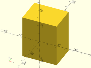
For cylindrical type attachables, the Z component of the vector will be −1, 0, or 1, referring to the bottom rim, the middle side, or the top rim of the cylindrical or conical shape. The X and Y components can be any value, pointing towards the circular perimeter of the cone. These combined let you point at any place on the bottom or top rims, or at an arbitrary side wall:
include <BOSL2/std.scad>
cylinder(r1=25, r2=15, h=60, anchor=TOP+LEFT);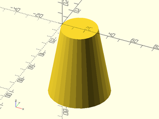
include <BOSL2/std.scad>
cylinder(r1=25, r2=15, h=60, anchor=BOTTOM+FRONT);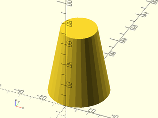
include <BOSL2/std.scad>
cylinder(r1=25, r2=15, h=60, anchor=UP+spherical_to_xyz(1,30,90));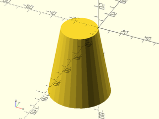
For Spherical type attachables, you can pass a vector that points at any arbitrary place on the surface of the sphere: p
include <BOSL2/std.scad>
sphere(r=50, anchor=TOP);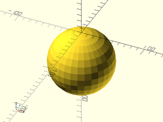
include <BOSL2/std.scad>
sphere(r=50, anchor=TOP+FRONT);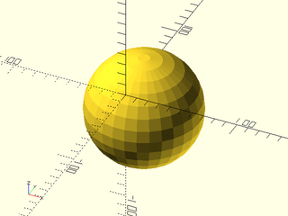
include <BOSL2/std.scad>
sphere(r=50, anchor=spherical_to_xyz(1,-30,60));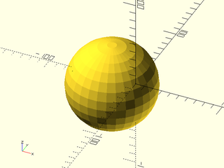
Some attachable shapes may provide specific named anchors for shape-specific anchoring. These
will be given as strings and will be specific to that type of
attachable. When named anchors are supported, they are listed in a
"Named Anchors" section of the documentation for the module. The
teardrop() attachable, for example, has a named anchor called "cap" and in 2D the
star() attachable has anchors labeled by tip number:
include <BOSL2/std.scad>
teardrop(d=100, l=20, anchor="cap");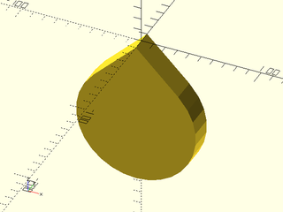
include <BOSL2/std.scad>
star(n=7, od=30, id=20, anchor="tip2");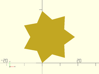
Some shapes, for backwards compatibility reasons, can take a center= argument. This just
overrides the anchor= argument. A center=true argument is the same as anchor=CENTER.
A center=false argument chooses the anchor to match the behavior of
the builtin version: for a cube it is the same as anchor=[-1,-1,-1] but for a
cylinder, it is the same as anchor=BOTTOM.
include <BOSL2/std.scad>
cube([50,40,30],center=true);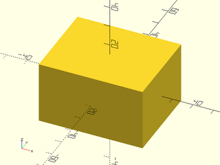
include <BOSL2/std.scad>
cube([50,40,30],center=false);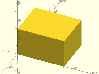
Most 2D shapes provided by BOSL2 are also anchorable. The built-in square() and circle()
modules have been overridden to make them attachable.. The anchor= options for 2D
shapes treat 2D vectors as expected. Special handling occurs with 3D
vectors: if the Y coordinate is zero and the Z coordinate is nonzero,
then the Z coordinate is used to replace the Y coordinate. This is
done so that you can use the TOP and BOTTOM names as anchor for 2D
shapes.
include <BOSL2/std.scad>
square([40,30], anchor=BACK+LEFT);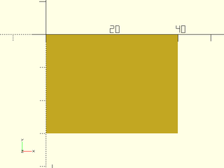
include <BOSL2/std.scad>
circle(d=50, anchor=BACK);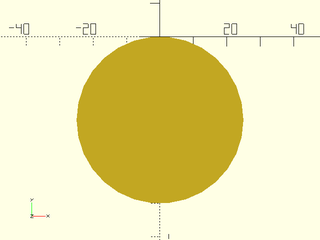
include <BOSL2/std.scad>
hexagon(d=50, anchor=LEFT);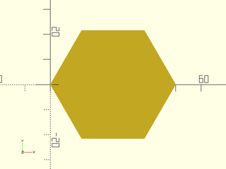
include <BOSL2/std.scad>
pentagon(d=50, anchor=TOP);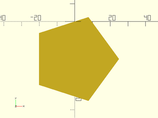
You can spin attachable objects around the origin using the spin=
argument. The spin applies after anchoring, so depending on how
you anchor an object, its spin may not be about its center. This
means that spin can have an effect even on rotationally symmetric
objects like spheres and cylinders. You specify the spin in degrees.
A positive number will result in a counter-clockwise spin around the Z
axis (as seen from above), and a negative number will make a clockwise
spin:
include <BOSL2/std.scad>
cube([20,20,40], center=true, spin=45);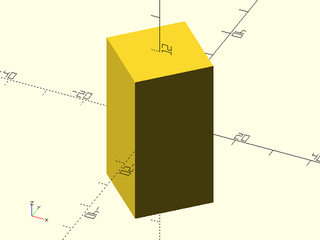
You can also spin around other axes, or multiple axes at once, by giving 3 angles (in degrees) to
spin= as a vector, like [Xang,Yang,Zang]. Similarly to rotate(),
the rotations apply in the order given, X-axis spin, then Y-axis, then Z-axis:
include <BOSL2/std.scad>
cube([20,20,40], center=true, spin=[10,20,30]);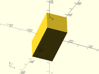
This example shows a cylinder which has been anchored at its FRONT, with a rotated copy in gray. The rotation is performed around the origin, but the cylinder is off the origin, so the rotation does have an effect on the cylinder, even though the cylinder has rotational symmetry.
include <BOSL2/std.scad>
cylinder(h=40,d=20,anchor=FRONT+BOT);
%cylinder(h=40.2,d=20,anchor=FRONT+BOT,spin=40);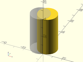
You can also apply spin to 2D shapes from BOSL2, though only by scalar angle:
include <BOSL2/std.scad>
square([40,30], spin=30);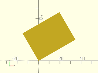
include <BOSL2/std.scad>
ellipse(d=[40,30], spin=30);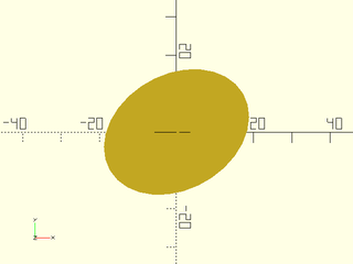
Another way to specify a rotation for an attachable shape, is to pass a 3D vector via the
orient= argument. This lets you specify what direction to tilt the top of the shape towards.
For example, you can make a cone that is tilted up and to the right like this:
include <BOSL2/std.scad>
cylinder(h=100, r1=50, r2=20, orient=UP+RIGHT);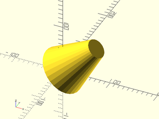
More precisely, the Z direction of the shape is rotated to align with
the vector you specify. Two dimensional attachables, which have no Z vector,
do not accept the orient= argument.
When giving anchor=, spin=, and orient=, they are applied anchoring first, spin second,
then orient last. For example, here's a cube:
include <BOSL2/std.scad>
cube([20,20,50]);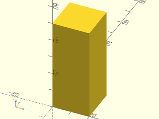
You can center it with an anchor=CENTER argument:
include <BOSL2/std.scad>
cube([20,20,50], anchor=CENTER);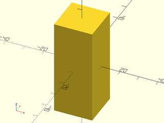
Add a 45 degree spin:
include <BOSL2/std.scad>
cube([20,20,50], anchor=CENTER, spin=45);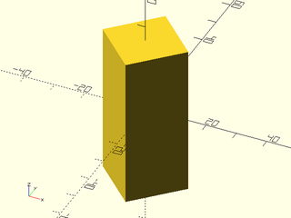
Now tilt the top up and forward:
include <BOSL2/std.scad>
cube([20,20,50], anchor=CENTER, spin=45, orient=UP+FWD);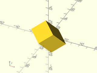
For 2D shapes, you can mix anchor= with spin=, but not with orient=.
include <BOSL2/std.scad>
square([40,30], anchor=BACK+LEFT, spin=30);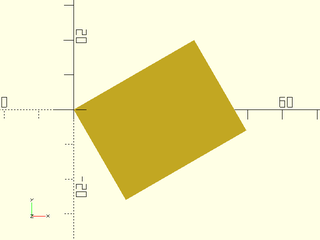
Positioning is a powerful method for placing an object relative to
another object. You do this by making the second object a child of
the first object. By default, the child's anchor point will be
aligned with the center of the parent. The default anchor for cyl()
is CENTER, and in this case, the cylinder is centered on the cube's center
include <BOSL2/std.scad>
up(13) cube(50)
    cyl(d=25,l=95);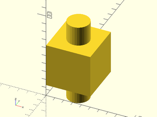
With cylinder() the default anchor is BOTTOM. It's hard to tell,
but the cylinder's bottom is placed at the center of the cube.
include <BOSL2/std.scad>
cube(50)
    cylinder(d=25,h=75);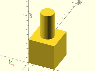
If you explicitly anchor the child object then the anchor you choose will be aligned with the center point of the parent object. In this example the right side of the cylinder is aligned with the center of the cube.
include <BOSL2/std.scad>
cube(50,anchor=FRONT)
    cylinder(d=25,h=95,anchor=RIGHT);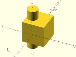
The position() module enables you to specify where on the parent to
position the child object. You give position() an anchor point on
the parent, and the child's anchor point is aligned with the specified
parent anchor point. In this example the LEFT anchor of the cylinder is positioned on the
RIGHT anchor of the cube.
include <BOSL2/std.scad>
cube(50,anchor=FRONT)
    position(RIGHT) cylinder(d=25,h=75,anchor=LEFT);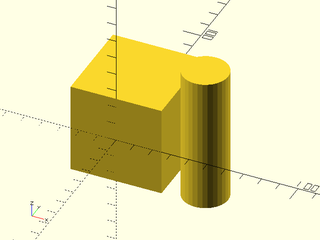
Using this mechanism you can position objects relative to other objects which are in turn positioned relative to other objects without having to keep track of the transformation math.
include <BOSL2/std.scad>
cube([50,50,30],center=true)
    position(TOP+RIGHT) cube([25,40,10], anchor=RIGHT+BOT)
       position(LEFT+FRONT+TOP) cube([12,12,8], anchor=LEFT+FRONT+BOT)
         cylinder(h=10,r=3);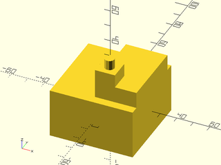
The positioning mechanism is not magical: it simply applies a
translate() operation to the child. You can still apply your own
additional translations or other transformations if you wish. For
example, you can position an object 5 units from the right edge:
include<BOSL2/std.scad>
cube([50,50,20],center=true)
    position(TOP+RIGHT) left(5) cube([4,50,10], anchor=RIGHT+BOT);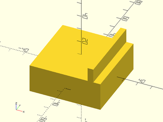
Positioning objects works the same way in 2D.
include<BOSL2/std.scad>
square(10)
    position(RIGHT) square(3,anchor=LEFT);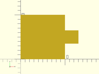
When positioning an object near an edge or corner you may wish to
orient the object relative to some face other than the TOP face that
meets at that edge or corner. You can always apply a rotation() to
change the orientation of the child object, but in order to do this,
you need to figure out the correct rotation. The orient() module provides a
mechanism for re-orienting the child() that eases this burden:
it can orient the child relative to the parent anchor directions. This is different
than giving an orient= argument to the child, because that orients
relative to the parent's global coordinate system by just using the vector
directly, instead of orienting to the parent's anchor, which takes
account of face orientation. A series of three
examples shows the different results. In the first example, we use
only position(). The child cube is erected pointing upwards, in the
Z direction. In the second example we use orient=RIGHT in the child
and the result is that the child object points in the X+ direction,
without regard for the shape of the parent object. In the final
example we apply orient(RIGHT) and the child is oriented
relative to the slanted right face of the parent using the parent
RIGHT anchor.
include<BOSL2/std.scad>
prismoid([50,50],[30,30],h=40)
  position(RIGHT+TOP)
     cube([15,15,25],anchor=RIGHT+BOT);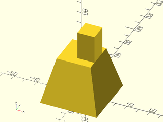
include<BOSL2/std.scad>
prismoid([50,50],[30,30],h=40)
  position(RIGHT+TOP)
     cube([15,15,25],orient=RIGHT,anchor=LEFT+BOT);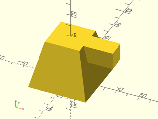
include<BOSL2/std.scad>
prismoid([50,50],[30,30],h=40)
  position(RIGHT+TOP)
     orient(RIGHT)
        cube([15,15,25],anchor=BACK+BOT);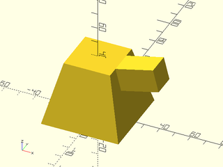
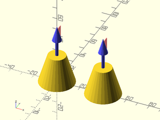
You may have noticed that the children in the above three examples have different anchors. Why is that? The first and second examples differ because anchoring up and anchoring to the right require anchoring on opposite sides of the child. But the third case differs because the spin has changed. The examples below show the same models but with arrows replacing the child cube. The red flags on the arrows mark the zero spin direction. Examine the red flags to see how the spin changes. The Y+ direction of the child will point towards that red flag.
include<BOSL2/std.scad>
prismoid([50,50],[30,30],h=40)
  position(RIGHT+TOP)
     anchor_arrow(40);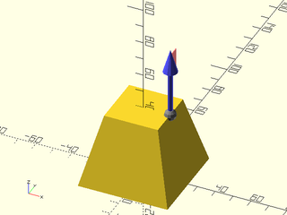
include<BOSL2/std.scad>
prismoid([50,50],[30,30],h=40)
  position(RIGHT+TOP)
     anchor_arrow(40, orient=RIGHT);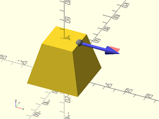
include<BOSL2/std.scad>
prismoid([50,50],[30,30],h=40)
  position(RIGHT+TOP)
     orient(RIGHT)
        anchor_arrow(40);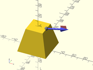
You may have noticed that with position() and orient(), specifying the child anchors to position objects flush with their parent can be annoying, or sometimes even tricky. You can simplify this task by using the align() module. This module positions children at specified anchor points on the parent while picking the correct anchor points on the children so that they line up with faces on the parent object.
In the simplest case, if you want to place a child on the RIGHT side of its parent, you need to anchor the child to its LEFT anchor:
include<BOSL2/std.scad>
cuboid([50,40,15])
    position(RIGHT)
        color("lightblue")cuboid(5,anchor=LEFT);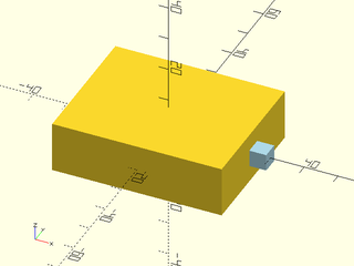
Using align(), the determination of the anchor is automatic. Any anchor you do specify is ignored.
include<BOSL2/std.scad>
cuboid([50,40,15])
    align(RIGHT)
        color("lightblue")cuboid(5);
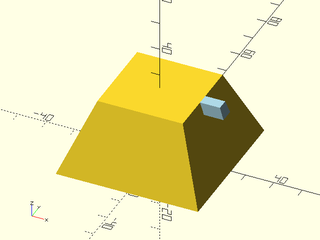
To place the child on top of the parent in the corner you can do use align as shown below instead of specifying the RIGHT+FRONT+BOT anchor with position():
include<BOSL2/std.scad>
cuboid([50,40,15])
    align(RIGHT+FRONT+TOP)
        color("lightblue")prismoid([10,5],[7,4],height=4);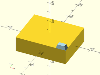
Both position() and align() can accept a list of anchor locations and makes several copies of the children, but if you want the children positioned flush, each copy requires a different anchor, so it is impossible to do this with a single call to position(), but easily done using align():
include<BOSL2/std.scad>
cuboid([50,40,15])
    align([RIGHT+TOP,LEFT+TOP])
        color("lightblue")prismoid([10,5],[7,4],height=4);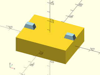
Align also accepts a spin argument, which lets you spin the child while still aligning it:
include<BOSL2/std.scad>
cuboid([50,40,15])
    align(RIGHT+TOP,spin=90)
        color("lightblue")prismoid([10,5],[7,4],height=4);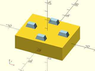
Note that this is different than using the spin argument to the child object, which will apply after alignment has been done.
include<BOSL2/std.scad>
cuboid([50,40,15])
    align(RIGHT+TOP)
        color("lightblue")prismoid([10,5],[7,4],height=4,spin=90);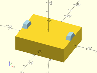
If you orient the object DOWN it will be attached from its top anchor:
include<BOSL2/std.scad>
cuboid([50,40,15])
    align(RIGHT+TOP,DOWN)
        color("lightblue")prismoid([10,5],[7,4],height=4);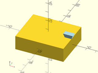
When placing children on the RIGHT and LEFT, there is a spin applied. This means that setting spin=0 changes the orientation. Here we have one object with the default and one object with zero spin:
include<BOSL2/std.scad>
prismoid(50,30,25){
  align(RIGHT+TOP,RIGHT,spin=0)
    color("lightblue")prismoid([10,5],[7,4],height=4);
  align(RIGHT+BOT,RIGHT)
    color("green")prismoid([10,5],[7,4],height=4);
}
Attachables get their name from their ability to be attached to each
other. Unlike with positioning, attaching changes the orientation of
the child object. When you attach an object, it appears on the parent
relative to the local coordinate system of the parent at the anchor point. To understand
what this means, imagine the perspective of an ant walking on a
sphere. The meaning of UP varies depending on where on the sphere the
ant is standing. If you attach a cylinder to the sphere then the cylinder will
be "up" from the ant's perspective. The first example shows a
cylinder placed with position() so it points up in the global parent
coordinate system. The second example shows how attach() points the
cylinder UP from the perspective of an ant standing at the anchor
point on the sphere.
include<BOSL2/std.scad>
sphere(40)
    position(RIGHT+TOP) cylinder(r=8,h=20);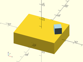
include<BOSL2/std.scad>
sphere(40)
    attach(RIGHT+TOP) cylinder(r=8,h=20);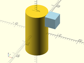
In the example above, the cylinder's center point is attached to the sphere, pointing "up" from the perspective of the sphere's surface. For a sphere, a surface normal is defined everywhere that specifies what "up" means. But for other objects, it may not be so obvious. Usually at edges and corners the direction is the average of the direction of the faces that meet there.
When you specify an anchor you are actually specifying both an anchor point but also an anchor direction. If you want to visualize this direction you can use anchor arrows.
For the ant on the sphere it is obvious which direction is UP; that direction corresponds to the Z+ axis. The location of the X and Y axes is less clear and in fact it may be arbitrary. One way that is useful to show the position and orientation of an anchor point is by attaching an anchor arrow to that anchor. As noted before, the small red flag points in the direction of the anchor's Y+ axis when the spin is zero.
include <BOSL2/std.scad>
cube(18, center=true)
    attach(LEFT+TOP)
        anchor_arrow();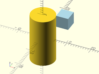
For large objects, you can change the size of the arrow with the s= argument.
include <BOSL2/std.scad>
sphere(d=100)
    attach(LEFT+TOP)
        anchor_arrow(s=50);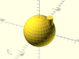
To show all the standard cardinal anchor points, you can use the show_anchors() module.
include <BOSL2/std.scad>
cube(40, center=true)
    show_anchors();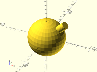
include <BOSL2/std.scad>
cylinder(h=40, d=40, center=true)
    show_anchors();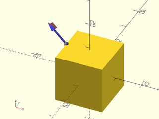
include <BOSL2/std.scad>
sphere(d=40)
    show_anchors();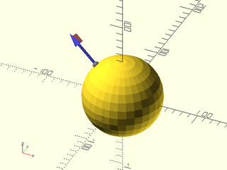
For large objects, you can again change the size of the arrows with the s= argument.
include <BOSL2/std.scad>
cylinder(h=100, d=100, center=true)
    show_anchors(s=30);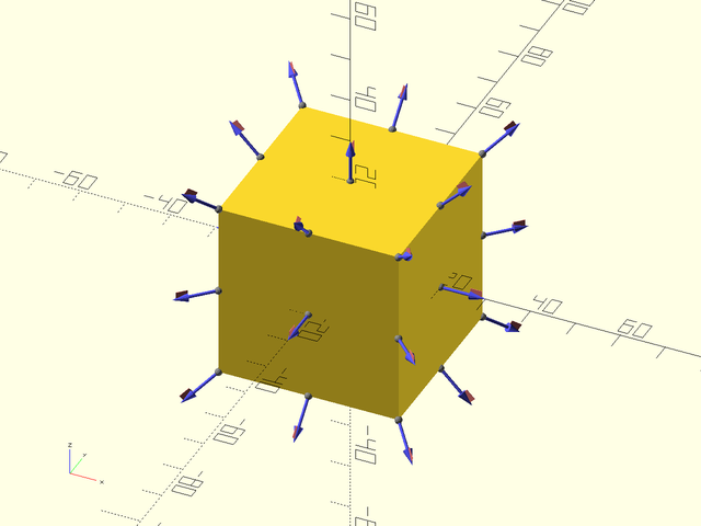
The simplest form of attachment is to attach using the attach()
module with a single argument, which specifies the anchor on the parent
where the child will attach. This will attach the bottom of the child
to the given anchor point on the parent. The child appears on the parent with its
Z direction aligned parallel to the parent's anchor direction, and
its Y direction pointing in the zero spin direction for the
parent anchor. The anchor direction of the child does not affect the result in this
case.
include <BOSL2/std.scad>
cube(50,center=true)
    attach(RIGHT)cylinder(d1=30,d2=15,h=25);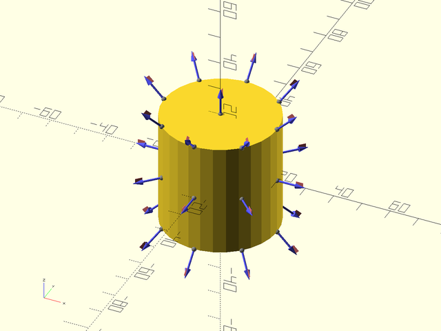
include <BOSL2/std.scad>
cube(50,center=true)
    attach(RIGHT+TOP)cylinder(d1=30,d2=15,h=25);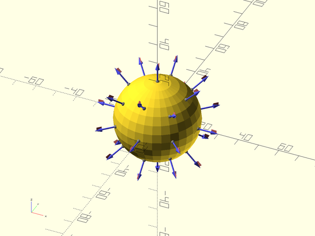
In the second example, the child object points diagonally away
from the cube. If you want the child at at edge of the parent it's
likely that this result will not be what you want. To get a different
result, use position() with orient(), if needed.
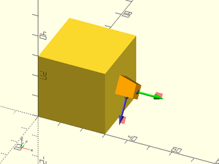
If you give an anchor point to the child object it moves the child around (in the attached coordinate system). Or alternatively you can think that it moves the object first, and then it gets attached.
include <BOSL2/std.scad>
cube(50,center=true)
    attach(RIGHT)cylinder(d1=30,d2=15,h=25,anchor=FRONT);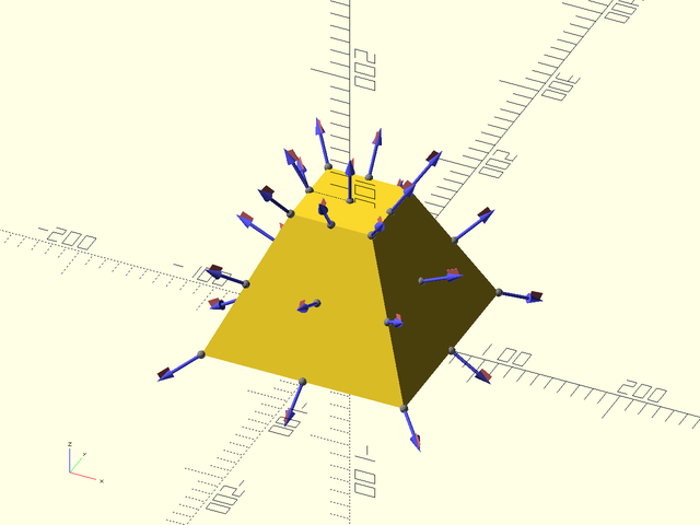
In the above example we anchor the child to its FRONT and then attach it to the RIGHT. An ambiguity exists regarding the spin of the parent's coordinate system. How is this resolved? The small flags on the anchor arrows show the position of zero spin by pointing towards the local Y+ direction, which is also the BACK direction of the child. For the above cube, the arrow looks like this:
include <BOSL2/std.scad>
cube(50,center=true)
    attach(RIGHT)anchor_arrow(30);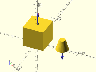
The red flag points up, which explains why the attached cylinder appeared above the anchor point. The CENTER anchor generally has a direction that points upward, so an attached object will keep its orientation if attached to the CENTER of a parent.
By default, attach() places the child exactly flush with the surface of the parent. Sometimes
it's useful to have the child overlap the parent by insetting a bit. You can do this with the
overlap= argument to attach(). A positive value will inset the child into the parent, and
a negative value will outset out from the parent, which may be helpful
when doing differences.
include <BOSL2/std.scad>
cube(50,center=true)
    attach(TOP,overlap=10)
        cylinder(d=20,h=20);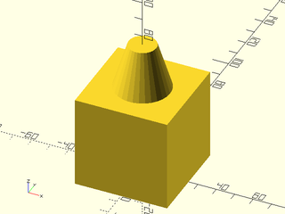
include <BOSL2/std.scad>
cube(50,center=true)
    attach(TOP,overlap=-20)
        cylinder(d=20,h=20);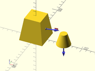
As with position(), you can still apply your own translations and
other transformations even after attaching an object. However, the
order of operations now matters. If you apply a translation outside
of the anchor then it acts in the parent's global coordinate system, so the
child moves up in this example:
include <BOSL2/std.scad>
cube(50,center=true)
    up(13)
        attach(RIGHT)
            cylinder(d1=30,d2=15,h=25);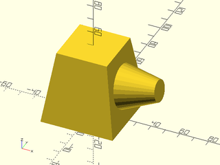
On the other hand, if you put the translation between the attach and the object in your code, then it will act in the local coordinate system of the parent at the parent's anchor, so in the example below it moves to the right.
include <BOSL2/std.scad>
cube(50,center=true)
    attach(RIGHT)
        up(13)
            cylinder(d1=30,d2=15,h=25);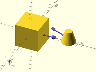
The attach() module can also take a second argument, the child anchor.
In this case, the attachment behavior
is quite different. The objects are still attached with their anchor
points aligned, but the child is reoriented so that its anchor
direction is the opposite of the parent anchor direction. It's like
you assemble the parts by pushing them together in the direction of
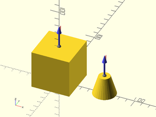
their anchor arrows. Two examples appear below, where first we show
two objects with their anchors and then we show the result of
attaching with those anchors.
include <BOSL2/std.scad>
cube(50,anchor=BOT) attach(TOP) anchor_arrow(30);
right(60)cylinder(d1=30,d2=15,h=25) attach(TOP) anchor_arrow(30);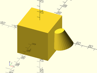
include <BOSL2/std.scad>
cube(50,anchor=BOT)
  attach(TOP,TOP) cylinder(d1=30,d2=15,h=25);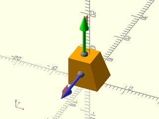
include <BOSL2/std.scad>
cube(50,center=true) attach(RIGHT) anchor_arrow(30);
right(80)cylinder(d1=30,d2=15,h=25) attach(LEFT) anchor_arrow(30);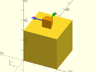
include <BOSL2/std.scad>
cube(50,center=true)
  attach(RIGHT,LEFT) cylinder(d1=30,d2=15,h=25);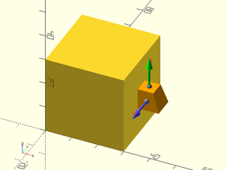
Note that when you attach with two anchors like this, the attachment
operation overrides any anchor or orientation specified in the
child. That means the child's anchor= and orient= options are
ignored.
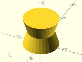
Attachment with CENTER anchors can be surprising because the anchors point upwards, so in the example below, the child's CENTER anchor points up, so it is inverted when it is attached to the parent cone. Note that the anchors are CENTER anchors, so the bases of the anchors are hidden in the middle of the objects.
include <BOSL2/std.scad>
cylinder(d1=30,d2=15,h=25) attach(CENTER) anchor_arrow(40);
right(40)cylinder(d1=30,d2=15,h=25) attach(CENTER) anchor_arrow(40);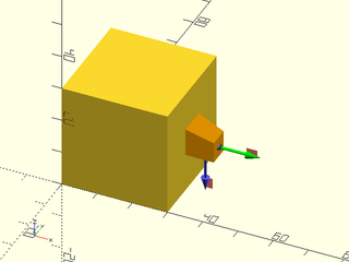
include <BOSL2/std.scad>
cylinder(d1=30,d2=15,h=25)
    attach(CENTER,CENTER)
        cylinder(d1=30,d2=15,h=25);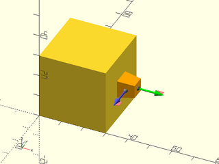
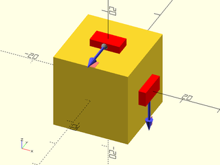
You can attach or position more than one child at a time by enclosing them all in braces:
include <BOSL2/std.scad>
cube(50, center=true) {
    attach(TOP) cylinder(d1=50,d2=20,h=20);
    position(RIGHT) cylinder(d1=50,d2=20,h=20);
}
If you want to attach the same shape to multiple places on the same parent, you can pass the
desired anchors as a list to the attach() or position() modules:
include <BOSL2/std.scad>
cube(50, center=true)
    attach([RIGHT,FRONT],TOP) cylinder(d1=35,d2=20,h=25);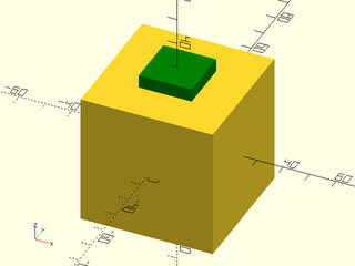
include <BOSL2/std.scad>
cube(50, center=true)
    position([TOP,RIGHT,FRONT]) cylinder(d1=35,d2=20,h=25);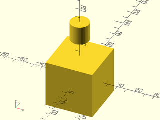
You can use attachments in 2D as well. As usual for the 2D case you can use TOP and BOTTOM as alternative to BACK and FORWARD.
include <BOSL2/std.scad>
square(50,center=true)
    attach(RIGHT,FRONT)
        trapezoid(w1=30,w2=0,h=30);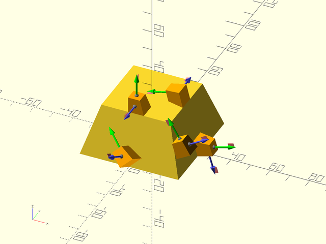
include <BOSL2/std.scad>
circle(d=50)
    attach(TOP,BOT,overlap=5)
        trapezoid(w1=30,w2=0,h=30);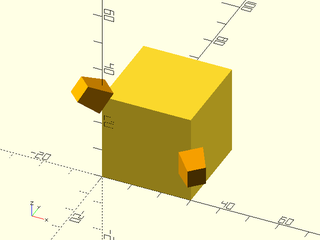
BOSL2 introduces the concept of tags. Tags are names that can be given to attachables, so that
you can refer to them when performing diff(), intersect(), and conv_hull() operations.
Each object can have no more than one tag at a time.
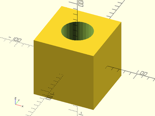
The diff() operator is used to difference away all shapes marked with the tag(s) given to
remove, from the other shapes.
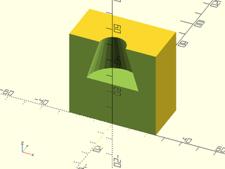
For example, to difference away a child cylinder from the middle of a parent cube, you can do this:
include <BOSL2/std.scad>
diff("hole")
cube(100, center=true)
    tag("hole")cylinder(h=101, d=50, center=true);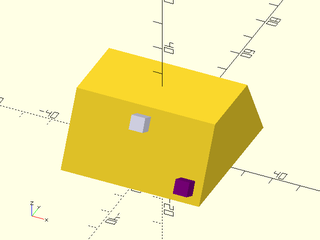
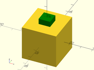
The keep= argument takes tags for shapes that you want to keep in the output.
include <BOSL2/std.scad>
diff("dish", keep="antenna")
cube(100, center=true)
    attach([FRONT,TOP], overlap=33) {
        tag("dish") cylinder(h=33.1, d1=0, d2=95);
        tag("antenna") cylinder(h=33.1, d=10);
    }
Remember that tags are inherited by children. In this case, we need to explicitly untag the first cylinder (or change its tag to something else), or it will inherit the "keep" tag and get kept.
include <BOSL2/std.scad>
diff("hole", "keep")
tag("keep")cube(100, center=true)
    attach([RIGHT,TOP]) {
        tag("") cylinder(d=95, h=5);
        tag("hole") cylinder(d=50, h=11, anchor=CTR);
    }
You can of course apply tag() to several children.
include <BOSL2/std.scad>
diff("hole")
cube(100, center=true)
    attach([FRONT,TOP], overlap=20)
        tag("hole") {
            cylinder(h=20.1, d1=0, d2=95);
            down(10) cylinder(h=30, d=30);
        }
Many of the modules that use tags have default values for their tags. For diff the default remove tag is "remove" and the default keep tag is "keep". In this example we rely on the default values:
include <BOSL2/std.scad>
diff()
sphere(d=100) {
    tag("keep")xcyl(d=40, l=120);
    tag("remove")cuboid([40,120,100]);
}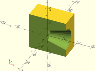
The parent object can be differenced away from other shapes. Tags are inherited by children, though, so you will need to set the tags of the children as well as the parent.
include <BOSL2/std.scad>
diff("hole")
tag("hole")cube([20,11,45], center=true)
    tag("body")cube([40,10,90], center=true);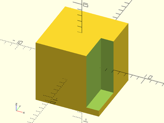
Tags (and therefore tag-based operations like diff()) only work correctly with attachable
children. However, a number of built-in modules for making shapes are not attachable.
Some notable non-attachable modules are text(), linear_extrude(), rotate_extrude(),
polygon(), polyhedron(), import(), surface(), union(), difference(),
intersection(), offset(), hull(), and minkowski().
To allow you to use tags-based operations with non-attachable shapes, you can wrap them with the
force_tag() module to specify their tags. For example:
include <BOSL2/std.scad>
diff("hole")
cuboid(50)
  attach(TOP)
    force_tag("hole")
      rotate_extrude()
        right(15)
          square(10,center=true);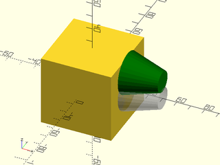
To perform an intersection of attachables, you can use the intersect() module. This is
specifically intended to address the situation where you want intersections involving a parent
and a child, something that is impossible with the native intersection() module. This module
treats the children in three groups: objects matching the intersect tags, objects matching
the tags listed in keep and the remaining objects that don't match any listed tags. The
intersection is computed between the union of the intersect tagged objects and the union of
the objects that don't match any listed tags. Finally the objects listed in keep are union
ed with the result.
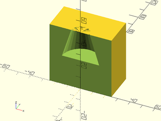
In this example the parent is intersected with a conical bounding shape.
include <BOSL2/std.scad>
intersect("bounds")
cube(100, center=true)
    tag("bounds") cylinder(h=100, d1=120, d2=95, center=true, $fn=72);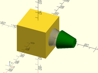
In this example the child objects are intersected with the bounding box parent.
include <BOSL2/std.scad>
intersect("pole cap")
cube(100, center=true)
    attach([TOP,RIGHT]) {
        tag("pole")cube([40,40,80],center=true);
        tag("cap")sphere(d=40*sqrt(2));
    }
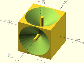
The default intersect tag is "intersect" and the default keep tag is "keep". Here is an
example where "keep" is used to keep the pole from being removed by the intersection.
include <BOSL2/std.scad>
intersect()
cube(100, center=true) {
    tag("intersect")cylinder(h=100, d1=120, d2=95, center=true, $fn=72);
    tag("keep")zrot(45) xcyl(h=140, d=20, $fn=36);
}
You can use the conv_hull() module to hull shapes together. Objects
marked with the keep tags are excluded from the hull and unioned into the final result.
The default keep tag is "keep".
include <BOSL2/std.scad>
conv_hull()
cube(50, center=true) {
    cyl(h=100, d=20);
    tag("keep")xcyl(h=100, d=20);
}
To make it easier to mask away shapes from various edges of an attachable parent shape, there
are a few specialized alternatives to the attach() and position() modules.
If you have a 3D mask shape that you want to difference away from various edges, you can use
the edge_mask() module. This module will take a vertically oriented shape, and will rotate
and move it such that the BACK, RIGHT (X+,Y+) side of the shape will be aligned with the given
edges. The shape will be tagged as a "remove" so that you can use
diff() with its default "remove" tag. For example,
here's a shape for rounding an edge:
include <BOSL2/std.scad>
module round_edge(l,r) difference() {
    translate([-1,-1,-l/2])
        cube([r+1,r+1,l]);
    translate([r,r])
        cylinder(h=l+1,r=r,center=true, $fn=quantup(segs(r),4));
}
round_edge(l=30, r=19);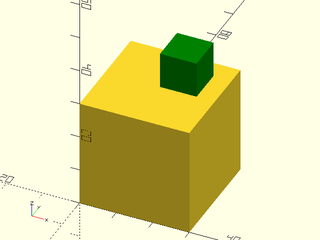
You can use that mask to round various edges of a cube:
include <BOSL2/std.scad>
module round_edge(l,r) difference() {
    translate([-1,-1,-l/2])
        cube([r+1,r+1,l]);
    translate([r,r])
        cylinder(h=l+1,r=r,center=true, $fn=quantup(segs(r),4));
}
diff()
cube([50,60,70],center=true)
    edge_mask([TOP,"Z"],except=[BACK,TOP+LEFT])
        round_edge(l=71,r=10);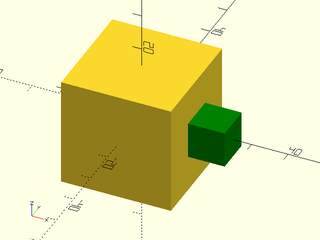
If you have a 3D mask shape that you want to difference away from various corners, you can use
the corner_mask() module. This module will take a shape and rotate and move it such that the
BACK RIGHT TOP (X+,Y+,Z+) side of the shape will be aligned with the given corner. The shape
will be tagged as a "remove" so that you can use diff() with its
default "remove" tag. For example, here's a shape for
rounding a corner:
include <BOSL2/std.scad>
module round_corner(r) difference() {
    translate(-[1,1,1])
        cube(r+1);
    translate([r,r,r])
        spheroid(r=r, style="aligned", $fn=quantup(segs(r),4));
}
round_corner(r=10);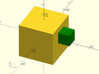
You can use that mask to round various corners of a cube:
include <BOSL2/std.scad>
module round_corner(r) difference() {
    translate(-[1,1,1])
        cube(r+1);
    translate([r,r,r])
        spheroid(r=r, style="aligned", $fn=quantup(segs(r),4));
}
diff()
cube([50,60,70],center=true)
    corner_mask([TOP,FRONT],LEFT+FRONT+TOP)
        round_corner(r=10);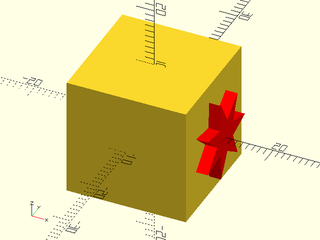
You can use edge_mask() and corner_mask() together as well:
include <BOSL2/std.scad>
module round_corner(r) difference() {
    translate(-[1,1,1])
        cube(r+1);
    translate([r,r,r])
        spheroid(r=r, style="aligned", $fn=quantup(segs(r),4));
}
module round_edge(l,r) difference() {
    translate([-1,-1,-l/2])
        cube([r+1,r+1,l]);
    translate([r,r])
        cylinder(h=l+1,r=r,center=true, $fn=quantup(segs(r),4));
}
diff()
cube([50,60,70],center=true) {
    edge_mask("ALL") round_edge(l=71,r=10);
    corner_mask("ALL") round_corner(r=10);
}
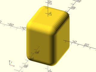
While 3D mask shapes give you a great deal of control, you need to make sure they are correctly
sized, and you need to provide separate mask shapes for corners and edges. Often, a single 2D
profile could be used to describe the edge mask shape (via linear_extrude()), and the corner
mask shape (via rotate_extrude()). This is where edge_profile(), corner_profile(), and
face_profile() come in.
Using the edge_profile() module, you can provide a 2D profile shape and it will be linearly
extruded to a mask of the appropriate length for each given edge. The resultant mask will be
tagged with "remove" so that you can difference it away with diff()
with the default "remove" tag. The 2D profile is
assumed to be oriented with the BACK, RIGHT (X+,Y+) quadrant as the "cutter edge" that gets
re-oriented towards the edges of the parent shape. A typical mask profile for chamfering an
edge may look like:
include <BOSL2/std.scad>
mask2d_roundover(10);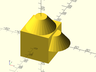
Using that mask profile, you can mask the edges of a cube like:
include <BOSL2/std.scad>
diff()
cube([50,60,70],center=true)
   edge_profile("ALL")
       mask2d_roundover(10);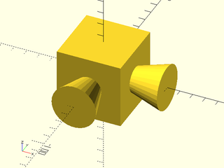
You can use the same profile to make a rounded corner mask as well:
include <BOSL2/std.scad>
diff()
cube([50,60,70],center=true)
   corner_profile("ALL", r=10)
       mask2d_roundover(10);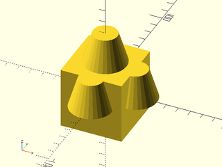
As a simple shortcut to apply a profile mask to all edges and corners of a face, you can use the
face_profile() module:
include <BOSL2/std.scad>
diff()
cube([50,60,70],center=true)
   face_profile(TOP, r=10)
       mask2d_roundover(10);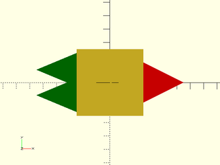
Usually, when coloring a shape with the color() module, the parent color overrides the colors of
all children. This is often not what you want:
include <BOSL2/std.scad>
$fn = 24;
color("red") spheroid(d=3) {
    attach(CENTER,BOT) color("white") cyl(h=10, d=1) {
        attach(TOP,BOT) color("green") cyl(h=5, d1=3, d2=0);
    }
}
If you use the recolor() module, however, the child's color
overrides the color of the parent. This is probably easier to understand by example:
include <BOSL2/std.scad>
$fn = 24;
recolor("red") spheroid(d=3) {
    attach(CENTER,BOT) recolor("white") cyl(h=10, d=1) {
        attach(TOP,BOT) recolor("green") cyl(h=5, d1=3, d2=0);
    }
}
Be aware that recolor() will only work if you avoid using the native
color() module. Also note that recolor() still affects all its
children. If you want to color an object without affecting the
children you can use color_this(). See the difference below:
include <BOSL2/std.scad>
$fn = 24;
recolor("red") spheroid(d=3) {
    attach(CENTER,BOT) recolor("white") cyl(h=10, d=1) {
        attach(TOP,BOT)  cyl(h=5, d1=3, d2=0);
    }
}
right(5)
recolor("red") spheroid(d=3) {
    attach(CENTER,BOT) color_this("white") cyl(h=10, d=1) {
        attach(TOP,BOT)  cyl(h=5, d1=3, d2=0);
    }
}
As with all of the attachable features, these color modules only work
on attachable objects, so they will have no effect on objects you
create using linear_extrude() or rotate_extrude().
To make a shape attachable, you just need to wrap it with an attachable() module with a
basic description of the shape's geometry. By default, the shape is expected to be centered
at the origin. The attachable() module expects exactly two children. The first will be
the shape to make attachable, and the second will be children(),
literally.
The simplest way to make your own attachable module is to simply pass
through to a pre-existing attachable submodule. This could be
appropriate if you want to rename a module, or if the anchors of an
existing module are suited to (or good enough for) your object. In
order for your attachable module to work properly you need to accept
the anchor, spin and orient parameters, give them suitable
defaults, and pass them to the attachable submodule. Don't forget to
pass the children to the attachable submodule as well, or your new
module will ignore its children.
include <BOSL2/std.scad>
$fn=32;
module cutcube(anchor=CENTER,spin=0,orient=UP)
{
   tag_scope(){
     diff()
       cuboid(15, rounding=2, anchor=anchor,spin=spin,orient=orient){
         tag("remove")attach(TOP)cuboid(5);
         children();
       }
   }
}
diff()
cutcube()
  tag("remove")attach(RIGHT) cyl(d=2,h=8);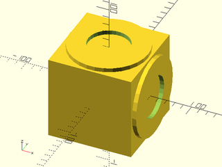
To make a cuboidal or prismoidal shape attachable, you use the size, size2, and offset
arguments of attachable().
In the most basic form, where the shape is fully cuboid, with top and bottom of the same size,
and directly over one another, you can just use size=.
include <BOSL2/std.scad>
module cubic_barbell(s=100, anchor=CENTER, spin=0, orient=UP) {
    attachable(anchor,spin,orient, size=[s*3,s,s]) {
        union() {
            xcopies(2*s) cube(s, center=true);
            xcyl(h=2*s, d=s/4);
        }
        children();
    }
}
cubic_barbell(100) show_anchors(60);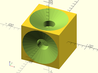
When the shape is prismoidal, where the top is a different size from the bottom, you can use
the size2= argument as well. While size= takes all three axes sizes, the size2= argument
only takes the [X,Y] sizes of the top of the shape.
include <BOSL2/std.scad>
module prismoidal(size=[100,100,100], scale=0.5, anchor=CENTER, spin=0, orient=UP) {
    attachable(anchor,spin,orient, size=size, size2=[size.x, size.y]*scale) {
        hull() {
            up(size.z/2-0.005)
                linear_extrude(height=0.01, center=true)
                    square([size.x,size.y]*scale, center=true);
            down(size.z/2-0.005)
                linear_extrude(height=0.01, center=true)
                    square([size.x,size.y], center=true);
        }
        children();
    }
}
prismoidal([100,60,30], scale=0.5) show_anchors(20);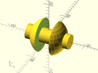
When the top of the prismoid can be shifted away from directly above the bottom, you can use
the shift= argument. The shift= argument takes an [X,Y] vector of the offset of the center
of the top from the XY center of the bottom of the shape.
include <BOSL2/std.scad>
module prismoidal(size=[100,100,100], scale=0.5, shift=[0,0], anchor=CENTER, spin=0, orient=UP) {
    attachable(anchor,spin,orient, size=size, size2=[size.x, size.y]*scale, shift=shift) {
        hull() {
            translate([shift.x, shift.y, size.z/2-0.005])
                linear_extrude(height=0.01, center=true)
                    square([size.x,size.y]*scale, center=true);
            down(size.z/2-0.005)
                linear_extrude(height=0.01, center=true)
                    square([size.x,size.y], center=true);
        }
        children();
    }
}
prismoidal([100,60,30], scale=0.5, shift=[-30,20]) show_anchors(20);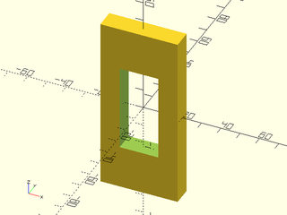
In the case that the prismoid is not oriented vertically, (ie, where the shift= or size2=
arguments should refer to a plane other than XY) you can use the axis= argument. This lets
you make prismoids naturally oriented forwards/backwards or sideways.
include <BOSL2/std.scad>
module yprismoidal(
    size=[100,100,100], scale=0.5, shift=[0,0],
    anchor=CENTER, spin=0, orient=UP
) {
    attachable(
        anchor, spin, orient,
        size=size, size2=point2d(size)*scale,
        shift=shift, axis=BACK
    ) {
        xrot(-90) hull() {
            translate([shift.x, shift.y, size.z/2-0.005])
                linear_extrude(height=0.01, center=true)
                    square([size.x,size.y]*scale, center=true);
            down(size.z/2-0.005)
                linear_extrude(height=0.01, center=true)
                    square([size.x,size.y], center=true);
        }
        children();
    }
}
yprismoidal([100,60,30], scale=1.5, shift=[20,20]) show_anchors(20);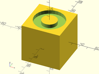
To make a cylindrical shape attachable, you use the l, and r/d, args of attachable().
include <BOSL2/std.scad>
module twistar(l,r,d, anchor=CENTER, spin=0, orient=UP) {
    r = get_radius(r=r,d=d,dflt=1);
    attachable(anchor,spin,orient, r=r, l=l) {
        linear_extrude(height=l, twist=90, slices=20, center=true, convexity=4)
            star(n=20, r=r, ir=r*0.9);
        children();
    }
}
twistar(l=100, r=40) show_anchors(20);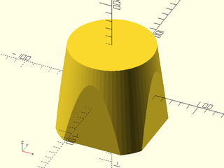
If the cylinder is elipsoidal in shape, you can pass the unequal X/Y sizes as a 2-item vector
to the r= or d= argument.
include <BOSL2/std.scad>
module ovalstar(l,rx,ry, anchor=CENTER, spin=0, orient=UP) {
    attachable(anchor,spin,orient, r=[rx,ry], l=l) {
        linear_extrude(height=l, center=true, convexity=4)
            scale([1,ry/rx,1])
                star(n=20, r=rx, ir=rx*0.9);
        children();
    }
}
ovalstar(l=100, rx=50, ry=30) show_anchors(20);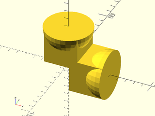
For cylindrical shapes that aren't oriented vertically, use the axis= argument.
include <BOSL2/std.scad>
module ytwistar(l,r,d, anchor=CENTER, spin=0, orient=UP) {
    r = get_radius(r=r,d=d,dflt=1);
    attachable(anchor,spin,orient, r=r, l=l, axis=BACK) {
        xrot(-90)
            linear_extrude(height=l, twist=90, slices=20, center=true, convexity=4)
                star(n=20, r=r, ir=r*0.9);
        children();
    }
}
ytwistar(l=100, r=40) show_anchors(20);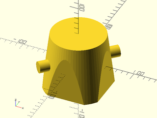
To make a conical shape attachable, you use the l, r1/d1, and r2/d2, args of
attachable().
include <BOSL2/std.scad>
module twistar(l, r,r1,r2, d,d1,d2, anchor=CENTER, spin=0, orient=UP) {
    r1 = get_radius(r1=r1,r=r,d1=d1,d=d,dflt=1);
    r2 = get_radius(r1=r2,r=r,d1=d2,d=d,dflt=1);
    attachable(anchor,spin,orient, r1=r1, r2=r2, l=l) {
        linear_extrude(height=l, twist=90, scale=r2/r1, slices=20, center=true, convexity=4)
            star(n=20, r=r1, ir=r1*0.9);
        children();
    }
}
twistar(l=100, r1=40, r2=20) show_anchors(20);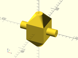
If the cone is ellipsoidal in shape, you can pass the unequal X/Y sizes as a 2-item vectors
to the r1=/r2= or d1=/d2= arguments.
include <BOSL2/std.scad>
module ovalish(l,rx1,ry1,rx2,ry2, anchor=CENTER, spin=0, orient=UP) {
    attachable(anchor,spin,orient, r1=[rx1,ry1], r2=[rx2,ry2], l=l) {
        hull() {
            up(l/2-0.005)
                linear_extrude(height=0.01, center=true)
                    ellipse([rx2,ry2]);
            down(l/2-0.005)
                linear_extrude(height=0.01, center=true)
                    ellipse([rx1,ry1]);
        }
        children();
    }
}
ovalish(l=100, rx1=50, ry1=30, rx2=30, ry2=50) show_anchors(20);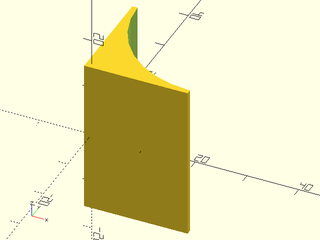
For conical shapes that are not oriented vertically, use the axis= argument to indicate the
direction of the primary shape axis:
include <BOSL2/std.scad>
module ytwistar(l, r,r1,r2, d,d1,d2, anchor=CENTER, spin=0, orient=UP) {
    r1 = get_radius(r1=r1,r=r,d1=d1,d=d,dflt=1);
    r2 = get_radius(r1=r2,r=r,d1=d2,d=d,dflt=1);
    attachable(anchor,spin,orient, r1=r1, r2=r2, l=l, axis=BACK) {
        xrot(-90)
            linear_extrude(height=l, twist=90, scale=r2/r1, slices=20, center=true, convexity=4)
                star(n=20, r=r1, ir=r1*0.9);
        children();
    }
}
ytwistar(l=100, r1=40, r2=20) show_anchors(20);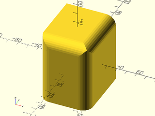
To make a spherical shape attachable, you use the r/d args of attachable().
include <BOSL2/std.scad>
module spikeball(r, d, anchor=CENTER, spin=0, orient=UP) {
    r = get_radius(r=r,d=d,dflt=1);
    attachable(anchor,spin,orient, r=r*1.1) {
        union() {
            sphere_copies(r=r, n=512, cone_ang=180) cylinder(r1=r/10, r2=0, h=r/10);
            sphere(r=r);
        }
        children();
    }
}
spikeball(r=50) show_anchors(20);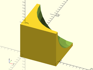
If the shape is an ellipsoid, you can pass a 3-item vector of sizes to r= or d=.
include <BOSL2/std.scad>
module spikeball(r, d, scale, anchor=CENTER, spin=0, orient=UP) {
    r = get_radius(r=r,d=d,dflt=1);
    attachable(anchor,spin,orient, r=r*1.1*scale) {
        union() {
            sphere_copies(r=r, n=512, scale=scale, cone_ang=180) cylinder(r1=r/10, r2=0, h=r/10);
            scale(scale) sphere(r=r);
        }
        children();
    }
}
spikeball(r=50, scale=[0.75,1,1.5]) show_anchors(20);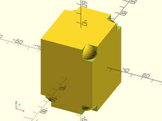
If the shape just doesn't fit into any of the above categories, and you constructed it as a
VNF, you can use the VNF itself to describe the geometry with the vnf= argument.
There are two variations to how anchoring can work for VNFs. When extent=true, (the default)
then a plane is projected out from the origin, perpendicularly in the direction of the anchor,
to the furthest distance that intersects with the VNF shape. The anchor point is then the
center of the points that still intersect that plane.
include <BOSL2/std.scad>
module stellate_cube(s=100, anchor=CENTER, spin=0, orient=UP) {
    s2 = 3 * s;
    verts = [
        [0,0,-s2*sqrt(2)/2],
        each down(s/2, p=path3d(square(s,center=true))),
        each zrot(45, p=path3d(square(s2,center=true))),
        each up(s/2, p=path3d(square(s,center=true))),
        [0,0,s2*sqrt(2)/2]
    ];
    faces = [
        [0,2,1], [0,3,2], [0,4,3], [0,1,4],
        [1,2,6], [1,6,9], [6,10,9], [2,10,6],
        [1,5,4], [1,9,5], [9,12,5], [5,12,4],
        [4,8,3], [4,12,8], [12,11,8], [11,3,8],
        [2,3,7], [3,11,7], [7,11,10], [2,7,10],
        [9,10,13], [10,11,13], [11,12,13], [12,9,13]
    ];
    vnf = [verts, faces];
    attachable(anchor,spin,orient, vnf=vnf) {
        vnf_polyhedron(vnf);
        children();
    }
}
stellate_cube(25) {
    attach(UP+RIGHT) {
        anchor_arrow(20);
        %cube([100,100,0.1],center=true);
    }
}
When extent=false, then the anchor point will be the furthest intersection of the VNF with
the anchor ray from the origin. The orientation of the anchor point will be the normal of the
face at the intersection. If the intersection is at an edge or corner, then the orientation
will bisect the angles between the faces.
include <BOSL2/std.scad>
module stellate_cube(s=100, anchor=CENTER, spin=0, orient=UP) {
    s2 = 3 * s;
    verts = [
        [0,0,-s2*sqrt(2)/2],
        each down(s/2, p=path3d(square(s,center=true))),
        each zrot(45, p=path3d(square(s2,center=true))),
        each up(s/2, p=path3d(square(s,center=true))),
        [0,0,s2*sqrt(2)/2]
    ];
    faces = [
        [0,2,1], [0,3,2], [0,4,3], [0,1,4],
        [1,2,6], [1,6,9], [6,10,9], [2,10,6],
        [1,5,4], [1,9,5], [9,12,5], [5,12,4],
        [4,8,3], [4,12,8], [12,11,8], [11,3,8],
        [2,3,7], [3,11,7], [7,11,10], [2,7,10],
        [9,10,13], [10,11,13], [11,12,13], [12,9,13]
    ];
    vnf = [verts, faces];
    attachable(anchor,spin,orient, vnf=vnf, extent=false) {
        vnf_polyhedron(vnf);
        children();
    }
}
stellate_cube() show_anchors(50);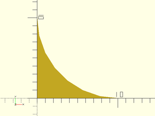
include <BOSL2/std.scad>
$fn=32;
R = difference(circle(10), right(2, circle(9)));
linear_sweep(R,height=10,atype="hull")
    attach(RIGHT) anchor_arrow();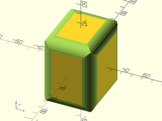
While vector anchors are often useful, sometimes there are logically extra attachment points that
aren't on the perimeter of the shape. This is what named string anchors are for. For example,
the teardrop() shape uses a cylindrical geometry for it's vector anchors, but it also provides
a named anchor "cap" that is at the tip of the hat of the teardrop shape.
Named anchors are passed as an array of named_anchor()s to the anchors= argument of attachable().
The named_anchor() call takes a name string, a positional point, an orientation vector, and a spin.
The name is the name of the anchor. The positional point is where the anchor point is at. The
orientation vector is the direction that a child attached at that anchor point should be oriented.
The spin is the number of degrees that an attached child should be rotated counter-clockwise around
the orientation vector. Spin is optional, and defaults to 0.
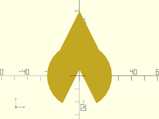
To make a simple attachable shape similar to a teardrop() that provides a "cap" anchor, you may
define it like this:
include <BOSL2/std.scad>
module raindrop(r, thick, anchor=CENTER, spin=0, orient=UP) {
    anchors = [
        named_anchor("cap", [0,r/sin(45),0], BACK, 0)
    ];
    attachable(anchor,spin,orient, r=r, l=thick, anchors=anchors) {
        linear_extrude(height=thick, center=true) {
            circle(r=r);
            back(r*sin(45)) zrot(45) square(r, center=true);
        }
        children();
    }
}
raindrop(r=25, thick=20, anchor="cap");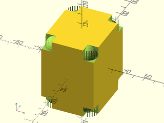
If you want multiple named anchors, just add them to the list of anchors:
include <BOSL2/std.scad>
module raindrop(r, thick, anchor=CENTER, spin=0, orient=UP) {
    anchors = [
        named_anchor("captop", [0,r/sin(45), thick/2], BACK+UP,   0),
        named_anchor("cap",    [0,r/sin(45), 0      ], BACK,      0),
        named_anchor("capbot", [0,r/sin(45),-thick/2], BACK+DOWN, 0)
    ];
    attachable(anchor,spin,orient, r=r, l=thick, anchors=anchors) {
        linear_extrude(height=thick, center=true) {
            circle(r=r);
            back(r*sin(45)) zrot(45) square(r, center=true);
        }
        children();
    }
}
raindrop(r=15, thick=10) show_anchors();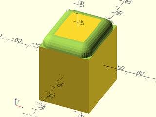
Sometimes the named anchor you want to add may be at a point that is reached through a complicated set of translations and rotations. One quick way to calculate that point is to reproduce those transformations in a transformation matrix chain. This is simplified by how you can use the function forms of almost all the transformation modules to get the transformation matrices, and chain them together with matrix multiplication. For example, if you have:
scale([1.1, 1.2, 1.3]) xrot(15) zrot(25) right(20) sphere(d=1);
and you want to calculate the center point of the sphere, you can do it like:
sphere_pt = apply(
    scale([1.1, 1.2, 1.3]) * xrot(15) * zrot(25) * right(20),
    [0,0,0]
);
Sometimes you may want to use the standard anchors but override some
of them. Returning to the square barebell example above, the anchors
at the right and left sides are on the cubes at each end, but the
anchors at x=0 are in floating in space. For prismoidal/cubic anchors
in 3D and trapezoidal/rectangular anchors in 2D we can override a single anchor by
specifying the override option and giving the anchor that is being
overridden, and then the replacement in the form
[position, direction, spin]. Most often you will only want to
override the position. If you omit the other list items then the
value drived from the standard anchor will be used. Below we override
position of the FWD anchor:
module cubic_barbell(s=100, anchor=CENTER, spin=0, orient=UP) {
    override = [
                 [FWD,  [[0,-s/8,0]]]
               ];
    attachable(anchor,spin,orient, size=[s*3,s,s],override=override) {
        union() {
            xcopies(2*s) cube(s, center=true);
            xcyl(h=2*s, d=s/4);
        }
        children();
    }
}
cubic_barbell(100) show_anchors(60);
Note how the FWD anchor is now rooted on the cylindrical portion. If you wanted to also change its direction and spin you could do it like this:
module cubic_barbell(s=100, anchor=CENTER, spin=0, orient=UP) {
    override = [
                 [FWD,  [[0,-s/8,0], FWD+LEFT, 225]]
               ];
    attachable(anchor,spin,orient, size=[s*3,s,s],override=override) {
        union() {
            xcopies(2*s) cube(s, center=true);
            xcyl(h=2*s, d=s/4);
        }
        children();
    }
}
cubic_barbell(100) show_anchors(60);
In the above example we give three values for the override. As before, the first one places the anchor on the cylinder. We have added the second entry which points the anchor off to the left. The third entry gives a spin override, whose effect is shown by the position of the red flag on the arrow. If you want to override all of the x=0 anchors to be on the cylinder, with their standard directions, you can do that by supplying a list:
module cubic_barbell(s=100, anchor=CENTER, spin=0, orient=UP) {
    override = [
                 for(j=[-1:1:1], k=[-1:1:1])
                   if ([j,k]!=[0,0]) [[0,j,k], [s/8*unit([0,j,k])]]
               ];
    attachable(anchor,spin,orient, size=[s*3,s,s],override=override) {
        union() {
            xcopies(2*s) cube(s, center=true);
            xcyl(h=2*s, d=s/4);
        }
        children();
    }
}
cubic_barbell(100) show_anchors(30);
Now all of the anchors in the middle are all rooted to the cylinder. Another
way to do the same thing is to use a function literal for override.
It will be called with the anchor as its argument and needs to return undef to just use
the default, or a [position, direction, spin] triple to override the
default. As before, you can omit values to keep their default.
Here is the same example using a function literal for the override:
module cubic_barbell(s=100, anchor=CENTER, spin=0, orient=UP) {
    override = function (anchor)
          anchor.x!=0 || anchor==CTR ? undef  // Keep these
        : [s/8*unit(anchor)];
    attachable(anchor,spin,orient, size=[s*3,s,s],override=override) {
        union() {
            xcopies(2*s) cube(s, center=true);
            xcyl(h=2*s, d=s/4);
        }
        children();
    }
}
cubic_barbell(100) show_anchors(30);