Basic build - fochica/fochica-wiki GitHub Wiki
The basic Fochica build supports a maximum of one parent connected at the same time, one child seat with two specific sensors; a capacitive sensor and an on/off sensor at the chest buckle. This is the recommended build to start with, especially for beginners.
This build requires no or minimal changes to the default Fochica Arduino code that is available on GitHub.
- Basic Arduino experience. Specifically with the Uno. It is assumed you know how to build basic circuits and upload sketches/code. If this is your first Arduino project look at the getting started guide.
- Basic Soldering skills are recommended. Preferably you will solder connections where relevant but you can also twist wires, use connectors, secure stuff with electrical/sticky tape and use a breadboard. Just understand that your connections might be less reliable if you are unable to solder.
If you feel that you lack the skills, perhaps one of your friends loves to build electronics and could help you. You can also seek assistance in your local maker or DIY space.
- PC with the Arduino suite - for programming the Arduino
- Android smartphone with Bluetooth Low Energy (BLE) - for interfacing with the device
- iOS support is in the roadmap, please sign up for a notification when it is available
- Digital Multi Meter - highly recommended - to troubleshoot the circuit and to measure values of parts
- Soldering tools - recommended - for making good electrical connections
- Crimper and crimp plugs or connectors of various size - optional - might be useful for connecting parts
See link on each part for a part selection and shopping guide.
- Arduino Uno - can be any working Arduino Uno or a clone
- HM-10 BLE module (or compatible clone) - must have a STATE pin
- Passive buzzer - one that can be driven by an Arduino
- 7-25+V to 5V step-down buck converter module - preferably one that is efficient at low currents
- Breadboard / perfboard / protoboard
- Resistors
- 1kΩ
- 10kΩ, a few
- 20kΩ, a few
- Wires
- Aluminum foil - for the capacitive sensor
- You will most likely need at least one of these parts to connect the device to a power source
- Cigarette/Cigar lighter plug - if you want to power from the cigarette socket/receptacle
- Fuse tap - if you need to rewire your cigarette socket for constant power
- OBD‐II plug - if you want to power from the OBD-II socket
- Logic level converter - if your BLE modules needs one and you choose this method
- NPN transistor - if your passive buzzer needs one
- For a Chest buckle sensor - if you want a second sensor on the seat for improved reliability
- Chest buckle - if your seat does not have one or if you don't want to mess with the existing one
- Magnetic reed switch - set of reed and magnet, such as ones used on doors or windows
- Misc connectors, plugs - whatever you want for your layout
- Capacitors
- between 10µF and 47µF - for improving stability of power supply and wireless modules
- For a Discharge protection circuit - if you want to prevent a case of dead car battery in a situation where the device discharges the battery while you are on a vacation, for example
- P-channel MOSFET, such as IRF9530
- N-channel MOSFET, "5V logic level", such as FQP30N06L
- 2 100KΩ resistors
- Momentary push-button
At the beginning it might be best to build the device in the "lab", on a comfortable desk near a PC. Once you are satisfied with how it is working, the next step would be to install the device in the car.
If after following the instructions in this section you are having difficulties or are unable to make the build work you can open an issue and we will try to advise.
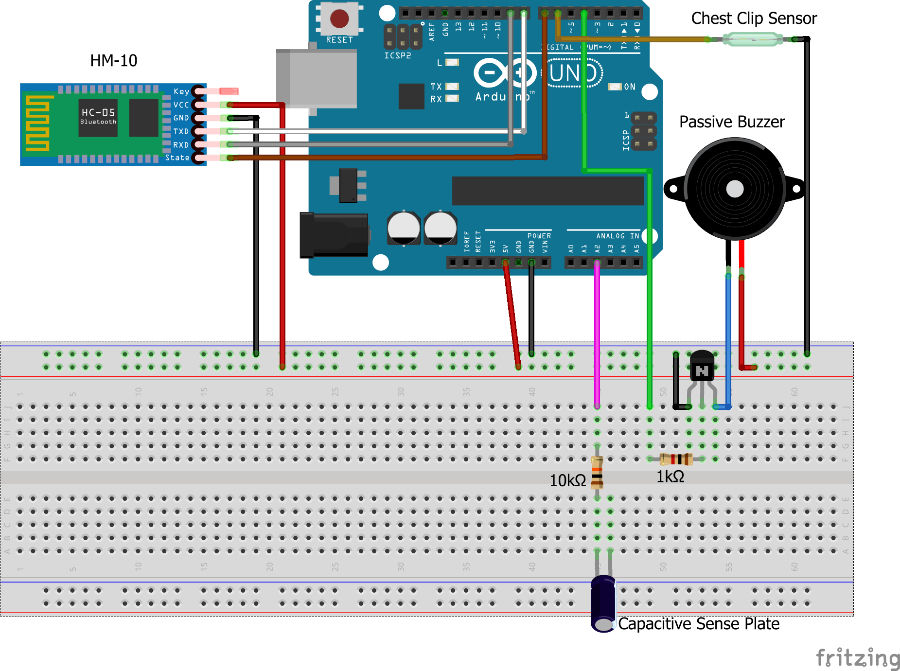
Build the following circuit (roughly)
Your buzzer may vary depending on what option you selected in the passive buzzer guide. The schematic above shows a bare-bone buzzer with a NPN transistor.
Your BLE module wiring may vary depending on what module you have. See BLE module guide for details. The schematic above shows an original HM-10 on a breakout board that supports 5V logic.
This schematic shows the use of a reed sensor on the chest buckle. If you have chosen not to implement a chest buckle sensor, ignore this part.
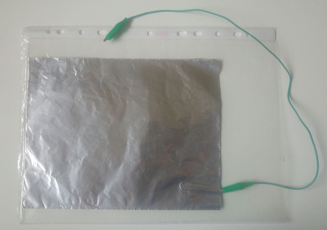
The capacitor labeled "Capacitive Sense Plate" is not an actual capacitor but a piece of aluminum foil. This will later go under the padding of the seat. Experiment with different sizes. A good option is to take a 30 cm by 40 cm sheet and fold it twice for a 4 layer thickness. Place the sheet in some kind of a bag, like a paper sheet protector or similar. Connect the sheet to pin A2 of Arduino through a 10K resistor. Here is an example of how you can assemble the "plate".
Perform the BLE module testing and configuring procedure. Follow the instructions of the Arduino BLE Ident-n-set sketch. The default pins in the menus should match the schematic above but adjust them if they are different than in your build.
See that your module is detected and identified properly by the sketch. If not, check your wiring and review the BLE module guide one more time. If the issue of the STATE pin has been raised by the sketch see about reconfiguring the STATE pin.
Now is also the opportunity to change the name of the module to something that will be easy for you to identify, such as "fochica1".
Get and upload to Arduino the Fochica Arduino code. The default code comes ready to use with the basic build. If you are using an PNP transistor with your buzzer, follow the instructions at transistors for passive buzzer.
Advanced user can make their customization at this point.
Power the device from USB, run the program. At start-up, the device will sound a short start tune. Verify that it occurs. Monitor the execution via the serial monitor (at 115200 baud) and see that there are no errors or messages that need attention.
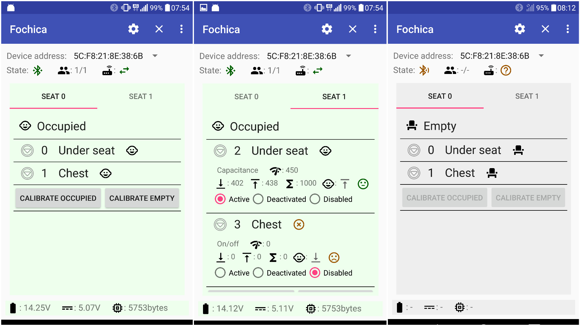
Install the Fochica Android app on an Android phone with BLE. Run the app. Add your BLE module at: Settings, Devices, Add. The app and the device should connect and the device should beep. Make sure that the main screen of the application now shows sensor state and a "connected" icon. Other phones or applications have to be disconnected from the module prior to any new connection attempts.
It is time to do a few functional tests.
Expand the panel of each sensor in the app by pressing on the "down arrow" icon. The raw reading from the sensor is shown next to the "gauge" icon.
If you have chosen not to implement the chest buckle sensor, disable it by clicking the "Disable" radio button. Otherwise open and close the magnetic reed sensor and observe the change in the raw value which should change from 0 to 1000.
Move your hand close to the capacitive sensor and then move it away. Observe the change in the raw value of the capacitive sensor.
Put the sensors in "empty" state (i.e. reed open and no touching the capacitive sensor) and press the "Calibrate Empty" button in the app. Then put the sensors in "occupied" state and press "Calibrate Occupied". Activate the sensors in various ways and see if the state of the sensors in the app changes accordingly.
Move in and out of range and verify that the app disconnects and re-connects to the device correctly.
If you observe any issue or are having compatibility problems, please send us feedback by opening an issue.
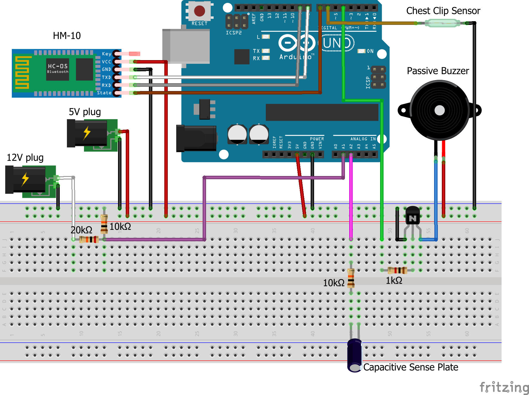
Once the device is working in the "lab" we can move to the next stage which is to prepare for in-car installation. The power source in the car is a 12V battery. In this stage we will add a DC-DC voltage converter to the circuit and a voltage divider to sense the car battery's voltage. If you haven't done so yet, please review the power source guide.
Add the new voltage divider and the plugs as shown in the following schematic:
The input of the DC-DC converter module (not shown in the schematic) and the "12V plug" should connect to the constant 12V power source. The output of the converter has to be connected to the Arduino USB port or to the points marked in the schematic as "5V plug".
Advanced users will also install a discharge protection circuit at this point in time.
Of course you can switch to a protoboard or perfboard and solder it all together. Some plugs can be ignored and wires can be soldered directly between components, but mind that the ability to unplug the sensors from the device or the device from the power source is very practical and useful.
Take a look at the different components you are going to have. Think where each part will go in the car.
If you haven't done so yet, please review the power source guide and decide how you will be powering the device.
Understand the limitations and decide on placement of the power cable, the device, sensors, etc. Measure lengths of the different cables, such as the power cable and sensor cables. Decide what kind of a box you will use to hold the electronics.
If you are going to use a chest buckle sensor, then now is the time to connect the magnetic reed switch to the chest buckle.
Once the components are installed in the car, run the basic tests again. Next, re-calibrate the sensors with and without your child and you are ready to go.
Once you feel comfortable with this build, or if you have special requirements you may want to try one of the more advanced builds. Remember, the system is open and extensible. If you wish to use different sensors or change some of the features, it is possible.
And don't forget to send us photos of your builds!


