Discharge protection circuit - fochica/fochica-wiki GitHub Wiki
The discharge protection circuit is an optional circuit that you can have on your Fochica device. This circuit will disconnect Fochica from power supply if it detects that the car's battery is at a predetermined, low voltage. This is meant as a last resort to prevent a dead car battery situation.
Once disconnected a button press will be necessary to boot the device back on, merely charging the battery (i.e. by driving) will not be sufficient.
How likely is one do discharge his car battery as a result of using Fochica? This depends on several factors, among which are:
- Capacity and age of battery
- Frequency of driving and engine starts
- Properties of your build, step down converter, LEDs running constantly, etc
- Improper configuration of the passive buzzer
- Ambient temperature
- Car type and condition (engine, starter, oil, etc)
Typical car batteries are at 40-50Ah, though it is hard to say how much of that capacity can be used before the remaining charge is no longer enough to start the engine. In comparison, a typical Fochica device will consume less than 50mA. In theory, if all the charge could be used for Fochica without loss of efficiency, that would be enough for 1000 hours of operation (50Ah/50mA). In practice, with a good battery you should have no issues having week long periods without driving without the risk of discharge.
If you are concerned, implement this circuit or do an experiment where you have Fochica running, don't start the car and measure the voltage daily to see when it goes below 11.5V. The battery voltage is shown in the status bar of the app (assuming you have implemented that part of the build).
Pros
- No risk of having a dead battery
Cons
- Additional parts are needed
- Additional assembly is required
- Have to press a button to boot the device if protection kicks in
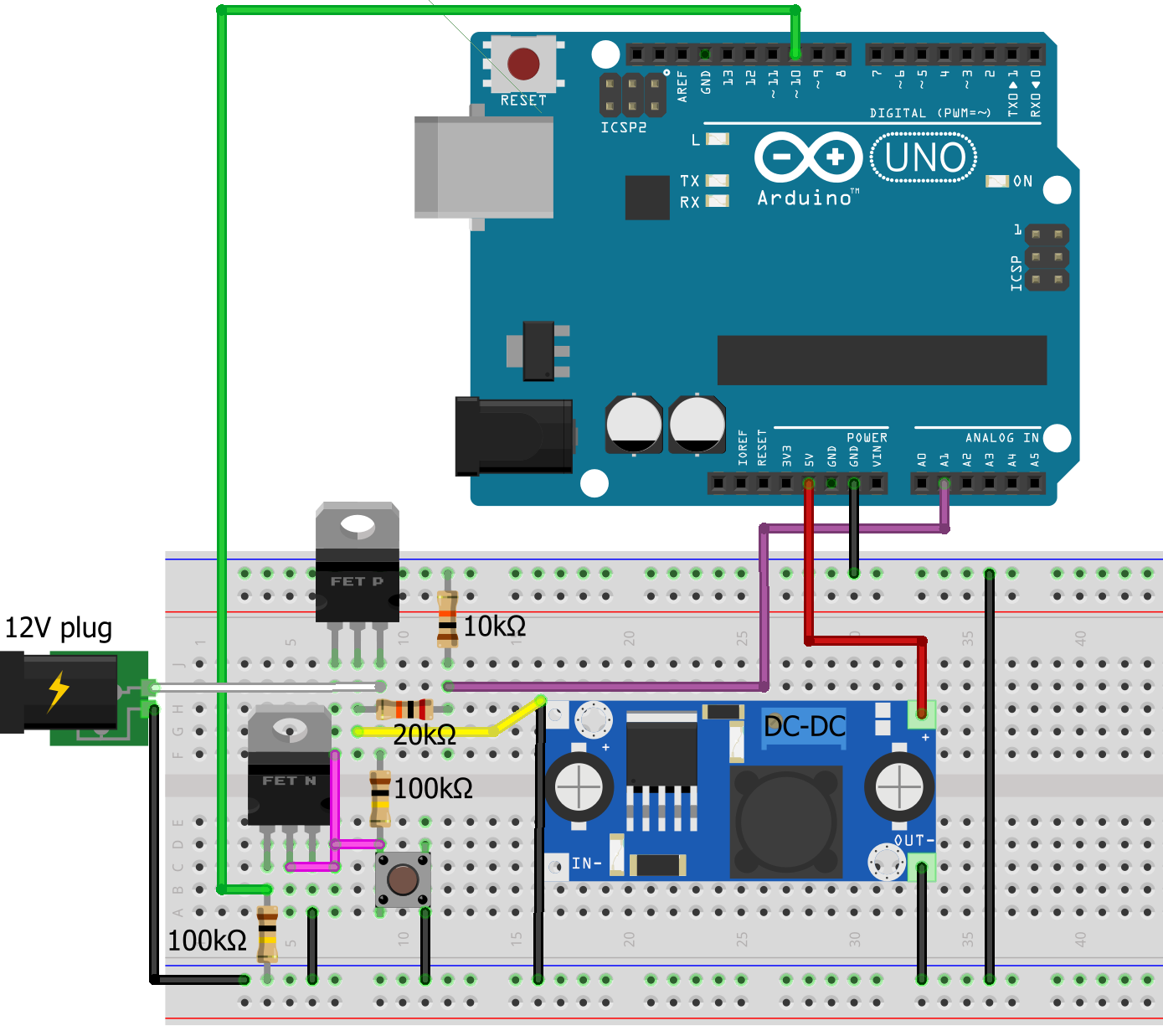
The circuit is based on transistors. Instead of being connected directly to the battery, the positive wire goes through a transistor which acts like a switch. Specifically, the circuit is designed with metal–oxide–semiconductor field-effect transistor (MOSFET) which is a type of transistor that switches based on voltage rather than current. This is an important property, as we don't want to consume any power while in the switched-off state.
You will need the following parts
- P-channel MOSFET, such as IRF9530
- N-channel MOSFET, "5V logic level", FQP30N06L
- 2 100KΩ resistors
- Momentary push-button
The current requirements for the MOSFETs are low (below 1A). Other MOSFETs that will also work are available in smaller form factors, but the examples above are easy to acquire online.
The P channel MOSFET is switching the high side, to preserve a common ground across the circuit. The P channel can be turned on if it is pulled low by either the switch or the N channel. When the Arduino starts (switch pressed), the code will pull the N channel high using a 5V signal, that will permanently turn the P channel on thus the button can be released. The Arduino can pull the N channel to low at any point and cause the power to disconnect. The Arduino senses the voltage of the battery through a voltage divider and can decide to trigger a disconnect when the battery reaches a pre-configured level. Once disconnected, the N channel is low and open and the switch is open too, so the P channel is high and open, preventing current flow.
Note that input pads of the DC-DC converter are messed up on the breadboard diagram. The black wire is connected to ground and the yellow to positive, even though they are show as touching the top left corner of the module.
The circuit is best used to switch the input of the step-down converter. If you switch the output of the converter, note that converters have a no-load current (usually around 1mA) so power will be used even of nothing is connected at output.
Might be able to do it with a Bipolar junction transistor BJT instead of the N-ch MOSFET or with two BJTs replacing both MOSFETs. Will need to add resistors on the bases and power efficiency will not be as good as with the MOSFETs.

