BLE module guide - fochica/fochica-wiki GitHub Wiki
A Bluetooth low energy (BLE) module is used in this system to allow the device to communicate with the smartphone of the user. Bluetooth low energy is a wireless technology that was designed by the Bluetooth group. BLE has a low power requirement compared to traditional Bluetooth and other comparable alternatives.
BLE is now commonly supported by smartphones and so it is a natural choice for a project like this.
There are many different BLE modules in the market and each has different capabilities and requirements. Thought support for additional modules can be added to Fochica, by default the Fochica code supports modules that are HM-10 compatible. HM-10 is a model of a BLE module that is popular with hobbyists particularly Arduino ones. It simplifies BLE by exposing a single characteristic via a serial connection. The HM-10 module is an "open post stamp" board that is meant to be soldered on top of another PCB.

This form factor is not popular in the Arduino community where modules typically have a "dupont" style (0.1" / 2.54mm) male/female connectors. Second, the module is 3.3V where typical Arduino boards (Uno specifically) are 5V. As a result, some manufacturers are offering the HM-10 on a breakout board. This exposes the few interesting pins in an easy to use form factor and takes care of the needed voltage conversion.

With time, various manufacturers have been making clones of the HM-10. This means that the daughter board is made by a different company than the original manufacturer (JNHuaMao Technology Company). Comparison (by JNHuaMao) of the original with clones:

Note how the original has a crystal in the upper left side of the module. The clones typically don't include such a crystal.
The breakout board can be different too. Often the breakout board is based on similar boards (i.e. ZS-040) used for non BLE Bluetooth modules (i.e. HC-05/06).
Note that typically clones have no logic conversion for the data pins. This means that the RX/TX pins need to get a 3.3V signal where the Arduino Uno will provide a 5V signal by default. Modules usually state that on the back of the PCB as "LEVEL" or specify this in the specification.
Clones typically do have a power conversion circuitry (voltage regulator) allowing you to power the module with 5V.
Clones can be of different types. Two types that have been tested successfully with Fochica are the CC41-A and the MLT-BT05.
Please note that different modules can have different pin order.
Example of a clone:


For building a Fochica, you will need one HM-10 compatible (original or clone) BLE module. You will need more than one if you want to allow for several adults to use the system at the same time.
The module must be on a breakout board.
The module must have a STATE pin, so modules with just 4 pins will not do. Look for a module with 6 pins. The STATE pin must be working. Please note that there have been instances of the MLT-BT05 module where the STATE pin was present but not soldered properly to the board. This can be fixed manually.
You will need to know what voltage your module needs for power and what voltage level for data. Note that originals that are fully adapted for 5V are more expensive but they will be easier to connect. The clones will most likely need additional components to connect properly.
Search for "hm-10 ble module". Sort the results by price. Look for listings showing a module with a breakout board and 6 pins.
Good price for an HM-10 clone is $2.8 to $3. An original HM-10 with a better breakout board (such as one by Keyes) will cost between $7 and $8.
If you are looking for an original, you will have to identify it visually in search results. Sort by "Best match" and look for a longer module with two crystals on the daughter board.
Connect Vcc and Gnd to the power source pins of Arduino. Add a voltage regulator if your module doesn't support 5V power.
If your module supports 5V logic:
Connect Rx on the module to Tx on the Arduino (Pin 9 by default, software serial).
Connect Tx on the module to Rx on the Arduino (Pin 8 by default, software serial).
Connect STATE on the module to Pin 7 (default) on the Arduino.
If your module expects 3.3V logic, follow the instructions in the next section.
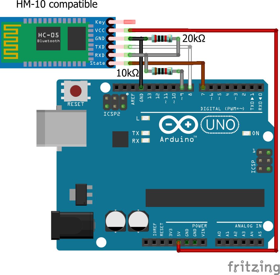
If your module need 3.3V level logic, we will need to scale down the Tx pin of the Arduino to a 3.3V level to not to damage the BLE module. This calculates to 3.3/5=66% of the original level. The Rx pin of the module needs no scaling, because 3.3V is in the proper logical range for Arduino already.
You can perform the conversion using different methods, two simple ones are suggested.
You will need two resistors with a 1:2 ratio, where the lower is between 1kΩ and 10kΩ. For examples a 10kΩ and 20kΩ will work. Similarly 1kΩ+2kΩ, 1kΩ+2.2kΩ, 4.7kΩ+10kΩ, etc.
Connect the higher value resistor to Gnd and the Rx pin of the module.
Connect the lower value resistor to the Tx on the Arduino (Pin 9 by default, software serial) and the Rx pin of the module.
Connect Tx on the module to Rx on the Arduino (Pin 8 by default, software serial).
Connect STATE on the module to Pin 7 (default) on the Arduino.
Take a look at Martyn Currey's article about an analogous HC-05 for additional information and code.
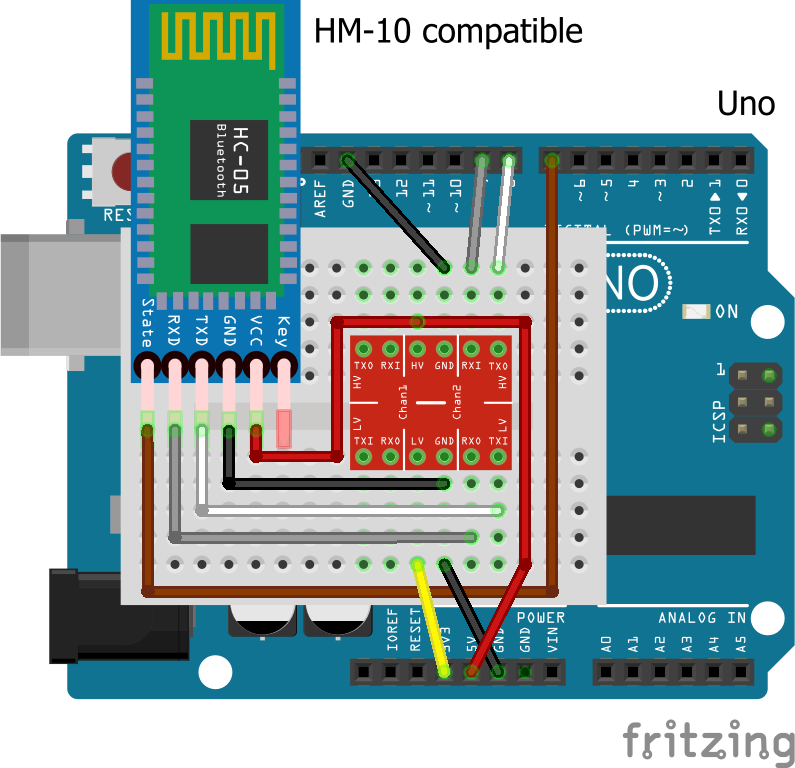
If you don't have the resistors available, prefer an elegant solution, or want to nail two modules at the same time, you can get a logic level converter module and connect it between the Arduino and the BLE module.
Once you have assembled the circuit as described above, power up the Arduino. The LED on the BLE module should be blinking (or if you have made a special configuration, off). If the LED is constantly on, identify the devices that are connected to the module and disable them. This may require exiting any paired Fochica applications or disconnecting from the nRF application, etc.
Newer Android version (from about 7) might require you to pair a BLE device for it to function properly with your phone. As a general rule, if you phone lists BLE devices in the Settings->Network->Bluetooth page then you should try to make a pairing while specifying the PIN of the module. The change is not well documented and can vary between different phone OEMs, it is best to experiment and see what works best for you, with pairing or without pairing.
Install the nRF Connect app on your phone and scan for BLE devices. If you can't identify the module, power down the Arduino and find the module through elimination.
Connect to the BLE module in the nRF app. The LED on the module should become constantly on. Close the tab to disconnect from the module.
If finding the device or connecting to it doesn't work or if the LED doesn't give any indication when connected and when disconnected your module might be defective or wired incorrectly. Seek assistance.
Get and upload to your Arduino the Arduino BLE module identification and setup sketch. Open the serial console at 9600 baud, CR&LF mode and interact with the prompts. Make sure that your module is identified and that there are no errors. If the module can't be found check your wiring. Try with or without the logic conversion if in doubt. If you are unable to resolve seek assistance.
If the "Arduino identification and setup" sketch mentioned that your "STATE" pin is "blinking", execute option #3, "Set module state pin behavior" in the menu and set the value to 1. This might affect the LED mode while disconnected and it will be off. Some HM-10 breakout boards are implemented this way where the LED and the STATE pin are one. In those cases the "blinking" must be disabled so not to confuse the Fochica code.
If you are having trouble with the BLE module and exhausted the suggestions above, you should ask for help at the Arduino Stack Exchange or the Electrical Engineering Stack Exchange. Please make sure to include photos of your module and a schematic of your circuit.
Martyn Currey's site has many different articles about BLE modules. One that is specifically interesting is a review of many different Bluetooth modules.