ProtoShield build - fochica/fochica-wiki GitHub Wiki
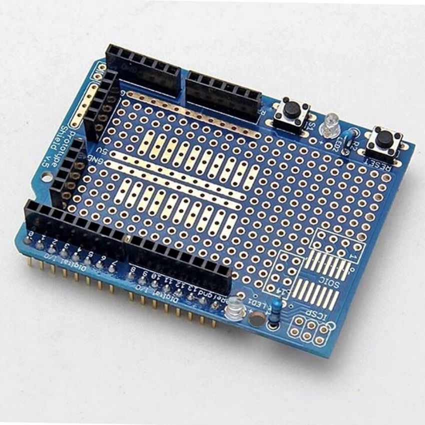
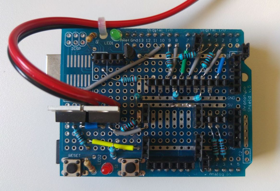
This build is a Fochica build where all the components are soldered on a ProtoShield. A ProtoShield is a type of a Perfboard in a shape of an (Arduino) shield.
The ProtoShield, unlike a breadboard, allows you to make a robust and permanent circuit. The ProtoShield has a certain fixed layout so it is limited compared to a custom PCB but much easier to acquire. Because the layout is limited, it is more difficult to assemble compared to placing components on a custom PCB, but it is still possible and the result is more compact and production ready than with a breadboard. So say goodbye to the breadboard and read on.
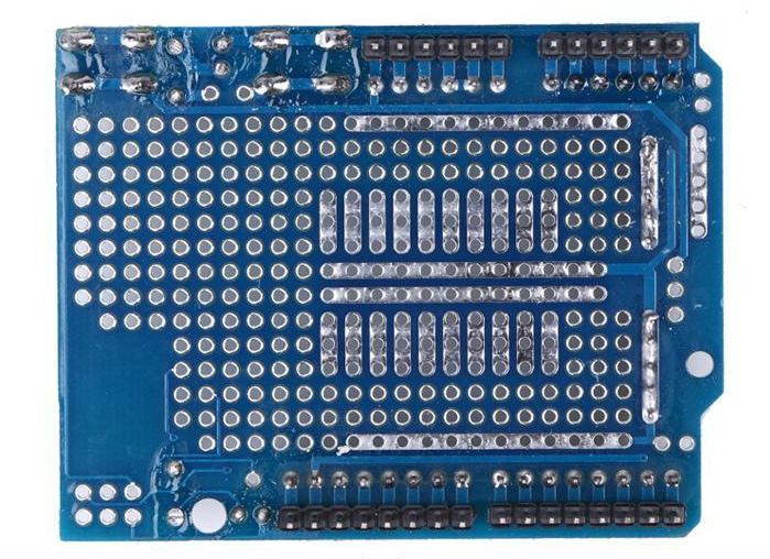
There are several options of ProtoShields with different layouts and of different sizes. This build uses an Arduino Uno and a proto shield design v.5 by Adafruit of which it is easy to get clones from the far east.
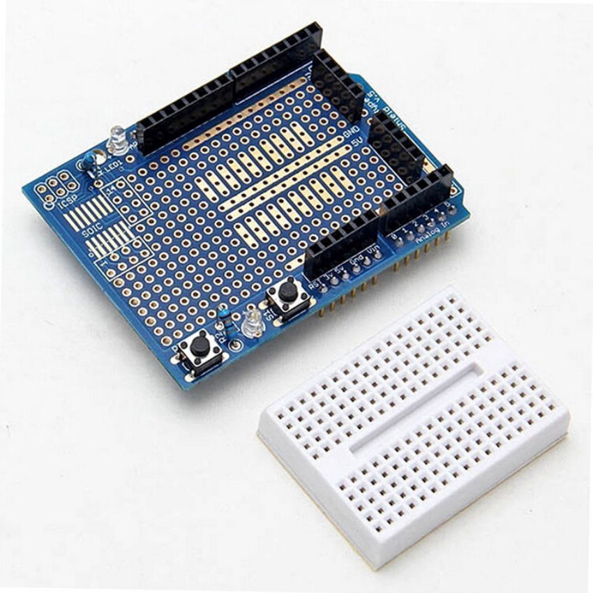
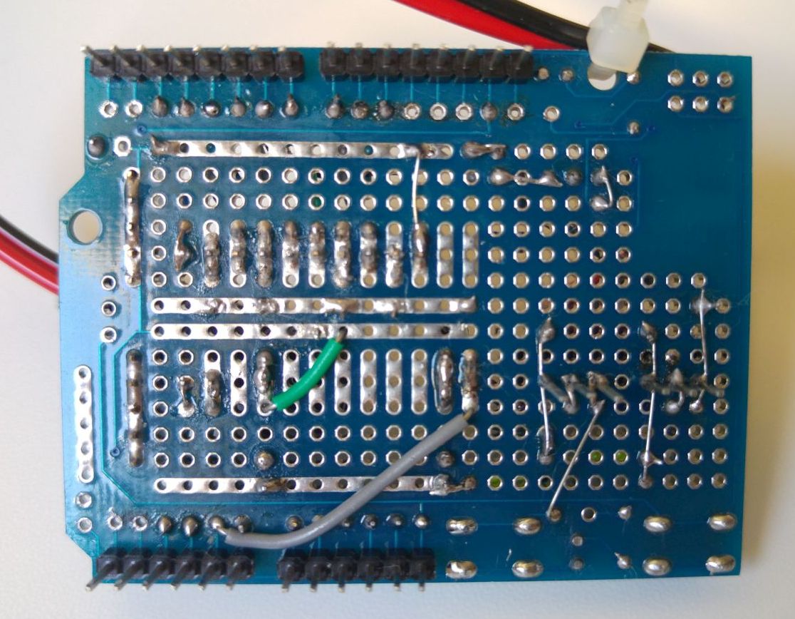
If you want to support Adafruit, you can get a latest version of their shield from them. If you are on a budget you can get the shield from other manufactures who make it based on the v.5 design. Search for "protoshield" on a shopping site and look for listings that match the photos included above. The back and front side of the shield are different, mind the specific side when comparing photos.
Most listing for this type of a shield come already assembled and with an included mini breadboard
You won't need the mini breadboard, but it is easier to accept it as a gift than to find a listing that doesn't include one. The typical cost of the whole set on eBay is about $1.5.
The shield includes two LEDs with resistors and two buttons, with one being a "reset" button and then other available for our use. Those, as well as the male and female headers are typically already soldered on the PCB, but it is possible to find this as a kit and solder the shield parts yourself.
This build will be based on the basic build expanded to support two BLE modules and two seats. A discharge protection circuit will be included as well.
First, you will need the components of the basic build.
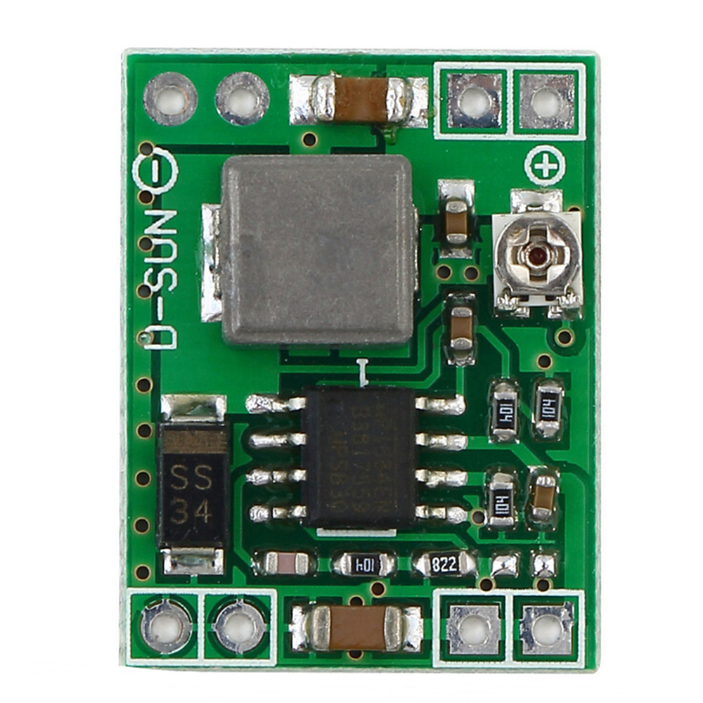
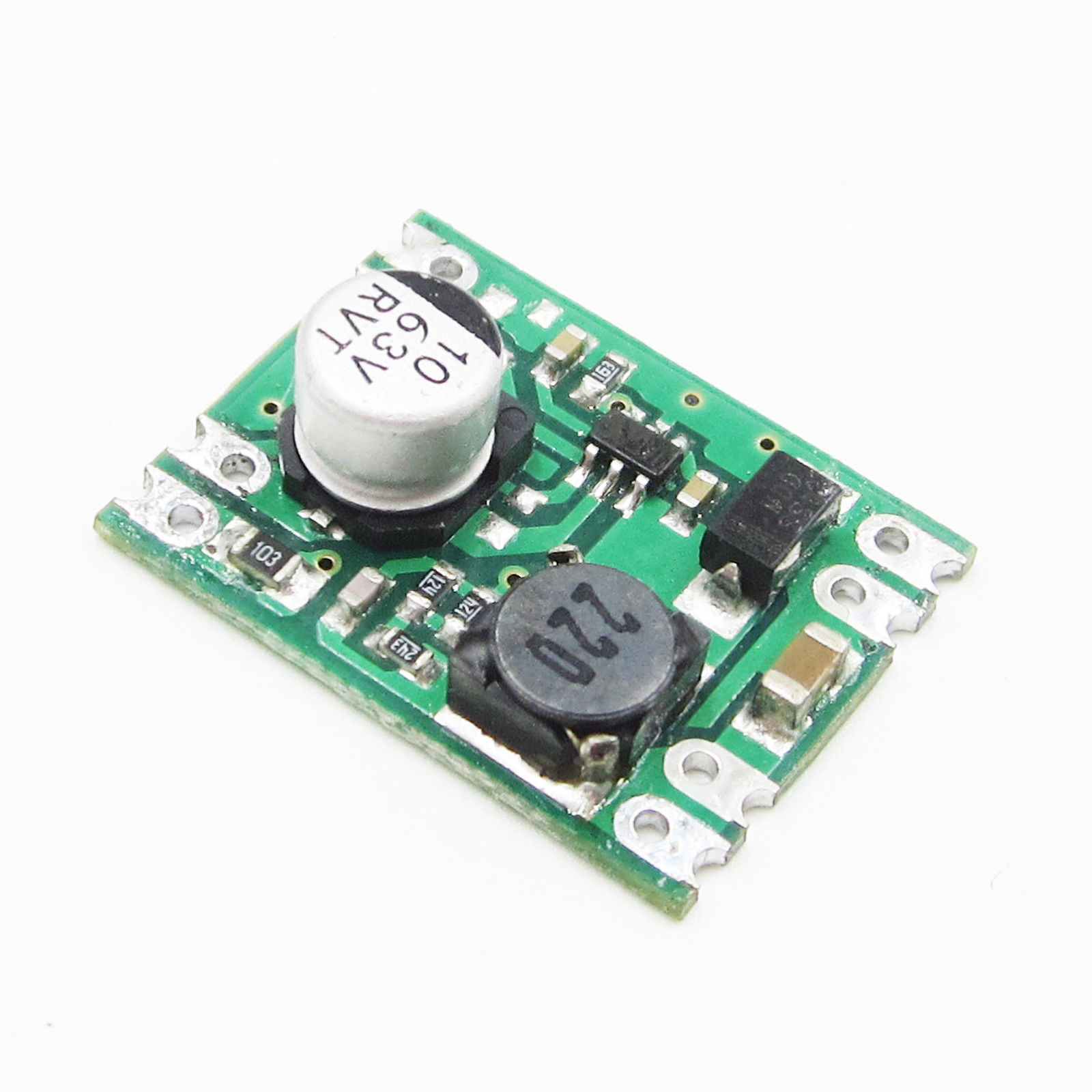
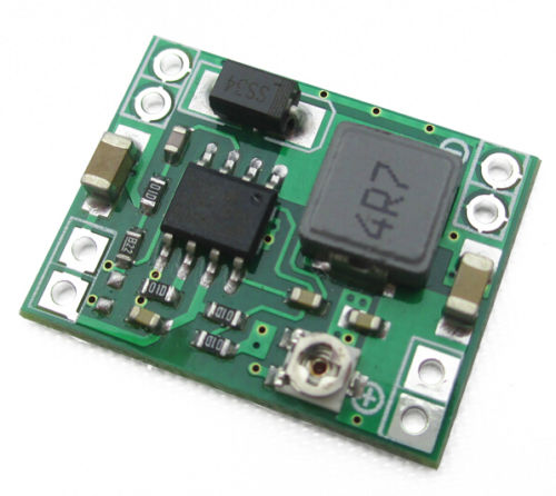
The DC converter has to be a "mini" module, about 22 by 16 mm. You can get a fixed version if you search for "DC-DC Step Down 5V Fixed" or the adjustable version is you search for "DC-DC Step Down 5V mini". Make sure that the input and output are on different ends of the module.
This build is designed to support two BLE modules which are HM-10 clones. The circuit features level conversion so that modules with 3.3v logic level can be used. Expected pin order is: STATE, RX, TX, GND, VCC, EN(not used). You don't have to use two modules if you only need to support one parent.
This build uses a passive buzzer that comes on a small PCB board with 3 pins. Two of the three pins are connected to the buzzer. The only reason for using this specifically was that the part was available. You can easily change the build to have the buzzer directly on the PCB or to use a buzzer board with a transistor built in. A 200Ω resistor was added in series with the buzzer to control its current. A NPN transistor drives the buzzer.
Next, you will need the components of the discharge protection circuit. There should be a button already available on the shield so you won't need to have another one, we will just connect to the existing one.
Additionally you will need:
- Female headers
- Solid core jumper wire
- DC female socket/plug with wire
- Soldering equipment
If you haven't done so already, build the circuit on a breadboard and test it.
If your shield came assembled, de-solder the analog and digital IO female headers and clean the holes/contacts. The removal would most likely be destructive for the headers.
If your shield came disassembled, solder the two momentary buttons.
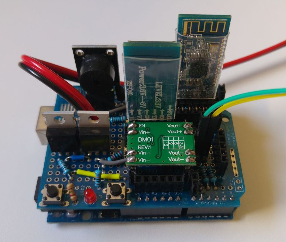
Solder the components in place as shown in the diagram and photos below. You can use the "ends" of the resistors and transistor to make connections to other points in the circuit. Fritzing diagram download.
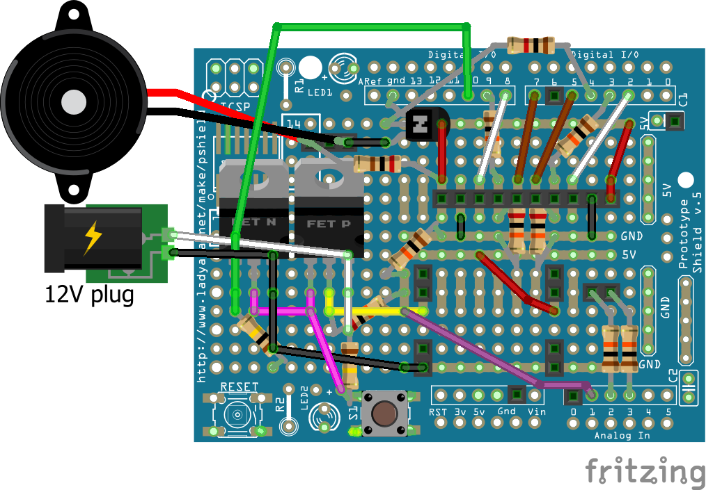
Note: the 20K resistor should go to the drain of the P-ch FET (as in the diagram) and not to the source (as in the photos). That is the latest design and it is more power efficient in a discharge protection scenario.
Schematic of the discharge protection circuit:
Additional schematics and layouts are in the basic build or BLE module guide pages.
Before connecting the other modules and the Arduino to the shield, plug in the DC converter module. Mind the orientation of the DC module. This build assumes "in" is on the left and "positive" is on top (relative to the photo). Test that there is proper voltage at the 5V pin.
Important: You will have to press the button on the right (not the reset button) to turn on the device due to the logic of the discharge protection circuit. Just connecting to power will not start the shield. At a later stage, once started manually, the software will put HIGH on D10 and this will keep the circuit running, so you will be able to let go of the button.
To enable code support for discharge protection, a second BLE module and a second seat go to the "SETTINGS" section of the main ino file. Uncomment the "ConfigVariation-UnoShieldV1.h" configuration and comment out any other configuration variation previously present. If you like, you can customize your configuration and create your own configuration having different features, pins and settings.
If power is working correctly, attach the buzzer, BLE module or modules and the capacitive or reed sensors. If you are using only one BLE module, install it in the left location. Note that the STATE pins go "in the middle" and the EN pins are "in the air".
Test, calibrate and install in the vehicle. Good job!
