Screens - subtilitas/rcbench GitHub Wiki
English · Deutsch
What is on every screen, what the menu marks mean, and how each screen is operated.
The top band is shared by every screen. From the right: STOP, the run clock (while ARMED or after a run), the arm chip, a FAULT code when one is reported, the mode, and LINK or NO LINK. The mode is BENCH while the link is up and the panel drives the coprocessor's outputs, and SIM while no coprocessor answers and the panel runs on its own models.
The arm chip names what the switch to ARMED drives:
| Chip | Outputs that drive |
|---|---|
| SAFE | none |
| ARMED MOTOR | the throttle outputs, from MOTOR & ESC or a stick run on PROGRAMMER; no surface and no programming port |
| ARMED SERVO | the surfaces and a pulsing PROG PORT, from SERVO; no throttle output |
| ARMED | every bound output, on a coprocessor older than protocol 4.18 |
STOP works on every screen. It switches to SAFE and latches: the bench stays SAFE until it is ARMED again. Navigating away, an alert expiring or the link recovering does not clear a stop.
ARM is at the bottom of a bench screen; STOP is at the top of the band.
A touch belongs to what it came down on until it lifts. The band is the top 48 px of the panel.
- A touch that comes down on the band stays the band's. Sliding it down into the screen moves nothing there, and lifting it there presses nothing.
- A touch that comes down on the screen and slides up into the band is released at the last point it had on the screen. A drag on a slider or on the SERVO dial ends with the value it had at that point, and the distance travelled on the band is not added. A hold on ARM or OUTPUT ON is abandoned. A button, a key, a tile, a tab or a list row under that point is not pressed: the release is the panel's and not the finger's. Three controls take it, because they stop something: DISARM, OUTPUT OFF and START TEST while a servo test runs. The touch is not picked up again when the finger comes back down onto the screen; lift and press again.
- A contact that is more than 120 px (the x and the y distance added) from where the previous report had it is taken as a lift there and a new press here. The touch controller is read every 10 ms; its report interval on the panel is not measured. That lift presses nothing either, with the same three exceptions and STOP. The new press is a press like any other, except on a key of the SETUP list, where it scrolls and steps nothing.
- STOP and the home tag answer to a press that lands on them. A finger that slides onto STOP from the screen stops nothing.
- A second finger on STOP, on the home tag or on the alert band is answered while the first finger drags. After the home tag, the finger still on the glass moves nothing on the screen the tag leads to.
A tap on a chip of the band opens a box under the band that says what the chip's state means for the bench and what to do: LINK or NO LINK, the mode, FAULT, the arm chip and the run clock. The box opens 4 px under the band at the tapped chip's left edge, moved left as far as it needs to stay 8 px inside the panel. It is 520 px wide; FAULT's box spans the panel (784 px), with one paragraph per set bit. No box reaches into the band, so none covers STOP, and none reaches the alert band.
- A tap opens it: press and lift on the same chip. A press that slides off the chip before it lifts opens nothing.
- The text follows the state while the box is open. A fault that appears shows at once, one that clears goes, and a box follows its chip when the run clock appears and moves the chips.
- A box whose chip goes closes: FAULT when the faults clear, the run clock when it goes.
- Any tap closes it and does nothing else. A tile, a button, another chip or the alert band under the finger is not pressed.
- STOP is the exception: a press on STOP closes the box and stops at once, as with no box.
- Leaving the screen closes it.
- A finger dragging on the screen when a second finger opens a box is released as at the band's edge.
While the link is up and the coprocessor has refused link frames, the LINK
box ends with the count, the same line MOTOR & ESC shows in its header
strip: Link frames refused: 37 (Refused frames).
The line follows the count while the box is open and goes with the link.
The FAULT box names each bit, its code and what it means:
| Code | Bit | Set by this release |
|---|---|---|
| 01 | LINK_SILENT | the coprocessor heard no request for 200 ms; stays until the next arm |
| 02 | OVERCURRENT | never |
| 04 | OVERTEMP | never |
| 08 | STALL | never |
| 10 | HEARTBEAT | the safety line from the panel stopped: after any STOP until the next arm, a pressed emergency stop or an open heartbeat wire |
| 20 | VERSION | never |
| 40 | STORE_OFF | the coprocessor cannot write its flash this boot |
For a bit this release never sets, or one the panel has no name for, the box says to flash both boards from one release.


A fault the screen itself does not show appears in a red band, 34 px high, across the bottom of every screen that has the status band. It covers the bottom of the screen, ARM included, while it shows.
- It clears 30 s after the frame it arrived in. A new alert, even with the same text, starts the 30 s again.
- A tap on the band clears it earlier: press and lift on the band, marked
with an
xat its right end. The screen beneath receives neither that tap nor a second finger's on the band; only the first finger's lift clears. - An alert that arrives while a finger is on the band is not cleared by that lift.
- "touch did not answer -- the bench will not switch to ARMED", shown at start, stays
until restart and has no
x: no touch is there to tap with. A later alert shows over it; once that one clears, it shows again.

A tile marked MODELLED opens a screen whose source the bench does not report: the coprocessor reports no capability for it, or its sensor is not enabled on SETUP under INTERFACES. A screen without its hardware opens and runs from the model. The mark does not classify each value on a screen. ANALYSER and BATTERY carry the mark and show no values. SERVO without the mark shows the panel's supply model as its rail meter when neither a PD mini nor an INA3221 is enabled. Each screen names the source of its readings itself.
| Tile | Without the mark when |
|---|---|
| MOTOR & ESC | the coprocessor drives ESCs and holds an INA228 set-up enabled on SETUP, INTERFACES |
| SERVO | the coprocessor drives servo PWM outputs |
| SUPPLY | the PD mini is enabled on SETUP, INTERFACES, whatever the coprocessor reports; otherwise the panel runs its own model of a supply |
| ANALYSER, BATTERY, BALANCE, PROGRAMMER | never in this release: no coprocessor reports these capabilities |
| LOGS, SETUP | always: they hold no measurement |
The capability bits come from the coprocessor at bring-up. With no coprocessor answering, MOTOR & ESC and SERVO carry the mark too.
The menu in the light theme:


Each subsystem reports its result as it comes up: board, display, touch, SD card, settings, link, coprocessor. The board line carries the panel's own firmware version, and the coprocessor line carries the protocol version and the firmware version that the coprocessor reported -- two boards can speak the same protocol and be different builds, and this is where that shows.
A missing card or an unusable NVS (non-volatile storage) is a warning. A touch controller that does not answer, or a coprocessor with a different protocol major version, is a failure and the bench does not switch to ARMED.
When every step has answered, the splash hands over to the menu after a hold of 1.6 s; a tap skips the hold.

Two columns. The plot and the throttle take the left, the four readouts and the controls take a rail on the right, so reading the numbers and working the throttle do not compete for the same part of the screen. With the rotary knob on, turning it moves the throttle (the knob).
The throttle panel names the pins the throttle drives, left of the percentage:
TARGET: GP0 GP1. They are the pins bound as MOTOR PWM or as a DShot
protocol, read from the same SETUP > OUTPUTS pages the coprocessor's throttle
role reads. The list is in pin order and holds as many pins as fit the field
of 49 characters; the rest are counted. With GP0 to GP15 bound it reads
TARGET: GP0 GP1 GP2 GP3 GP4 GP5 GP6 GP7 GP8 +7.
Two states show in the warning colour:
| Line | Condition |
|---|---|
TARGET: NO PIN BOUND AS MOTOR |
the binding is read and no pin is bound as a motor |
TARGET: BINDING NOT READ |
no binding was read: the link is down, the pages did not read, or no pin map exists for the board |
The throttle still moves in either state. ARM switches the whole bank to ARMED, not only the pins named here.

The trace is the record of a run. It advances only while the bench is ARMED:
switching to ARMED clears it, switching to SAFE holds it as it stood. The panel tag reads
LIVE TELEMETRY while it advances, TELEMETRY HELD while it holds a run, and
TELEMETRY IDLE before the first switch to ARMED, when the plot reads no run recorded.
The right-hand axis label reads NOW while it advances and END where a held
one stopped. The readouts, the TABLE pane, the totals and the temperature
strip are live at all times, ARMED or not.
The window is 534 columns at 20 samples per second, 26.7 s. A longer run holds its last 26.7 s; what came before is in the CSV file and not on the screen.
The trace ends at the switch to SAFE, not when the motor stops. Switching to SAFE commands zero throttle and the propeller coasts down after it. That coast-down is on the readouts and not on the plot, and not in the CSV file either, which closes on the same edge.
Switching to ARMED clears the plot, and a latched stop is cleared by switching to ARMED, so the trace of a run a STOP ended does not survive making the bench usable again. One switching to ARMED writes one CSV file, and the log viewer plots it.
The strip above both columns carries the poll rate, the link's error count
(cyclic redundancy check failures and resyncs added together) and three
temperatures. ESC and MOT come from the bench page. MCU is the panel's own
die, read from the ESP32-S3's sensor: it is the display board's temperature,
not the coprocessor's. While the link is up and the coprocessor has refused
link frames since its power-up, the strip shows how many after the error
count: Link frames refused: 37. A coprocessor older than protocol 4.21
sends no count, and the strip shows none
(Refused frames).

The throttle moves by how far a finger travels, not to where it lands. A press
on the track commands nothing, so a touch at the far end asks for nothing; a
drag across the whole track asks for the whole span, and the pin follows it
unramped. -1 and +1 at the ends of the track step one percentage point.
The throttle changes only while the bench is ARMED. What each control does:
| Control | SAFE | ARMED |
|---|---|---|
| The track | refused: no command, the slider and the readout stay; drawn dimmed | moves the throttle by the finger's travel |
-1, +1
|
refused; drawn dimmed | step one percentage point |
| Rotary knob | refused; the turn is not kept | moves the throttle from its value |
| ARM | switches the throttle outputs to ARMED after its 2 s hold; drawn disabled and without effect while the servo programmer holds a port | switches to SAFE on a tap |
| RESET PEAKS | resets the peaks | resets the peaks |
| PLOT, TABLE | switch the pane | switch the pane |
While SAFE, the line under the track reads ARM FIRST. The refusal runs
from the switch to SAFE until the bench reports ARMED: a control touched after
the ARM hold completes and before that report is refused too. From a DISARM the
screen asks for, by the tap or by leaving, or a STOP while the bench is ARMED,
until the bench reports SAFE, the controls are refused too.
A switch to SAFE returns the throttle to 0 %, however it happens: the DISARM tap,
STOP, a lost link, a touch controller that stops answering, or leaving the
screen. The slider, the readout and the -1 and +1 steps then stay at
0.0 % until the next switch to ARMED, so the first +1 after a switch to ARMED asks for 1.0 % and
the first 1 % turn of the knob asks for 1.0 %. A bench switched to ARMED without the ARM
hold, by a stick run on PROGRAMMER, starts from 0 % as well. A throttle the
screen has posted and the panel has not sent when the bench switches to SAFE is not
sent. A finger on the track when the bench switches to ARMED or to SAFE moves nothing
until it lifts and presses again.
ARM is a hold. The fill fades from green to the danger red across two seconds, and the bench switches to ARMED when the fade completes; letting go before then switches nothing, and the release itself switches nothing either.
The finger has to stay on the button. One that leaves it abandons the hold, because the gesture is contact with the control and not with the panel. Coming back is not resuming: the contact is finished as far as ARM is concerned, so a switch to ARMED after that takes lifting the finger and pressing again. A bench that switches to SAFE under a finger still held on the button ends the gesture too — otherwise the contact made to stop it would switch it to ARMED again two seconds later. The switch to ARMED flashes the whole button twice: white, black, red, and again, one drawn frame each. While ARMED, the button carries the danger red, and DISARM is a press rather than a hold: stopping never needs a hold. DISARM and STOP stop the output immediately, with no ramp. RESET PEAKS clears the peak markers and leaves the live readings.
The telemetry panel's header shows the rated kV, the revolutions per minute per volt the motor is actually turning, and EFF, the second divided by the first.
The arithmetic behind it is sound. Terminal voltage divides into the resistive drop and the back electromotive force (back-EMF), so rpm/V under load is the rated kV scaled by the fraction of the voltage that reaches the back-EMF, and that fraction is the fraction of the input power that becomes mechanical. In an ideal motor the ratio is the conversion efficiency exactly.
The number on the screen is not that, for three reasons, and it is labelled EFF rather than efficiency because of them:
- It accounts for copper loss (I squared R) only. Iron loss, friction and windage fall on the mechanical side of the split, so the figure is an upper bound on shaft efficiency rather than a value of it.
- The bench measures pack voltage, not the motor's terminals, so the ESC's conduction and switching losses are inside the figure. It describes the drivetrain, and comparing it against a motor datasheet compares two different things.
- It is only as good as the rated kV. An error there maps straight into the percentage, and a figure above 100 % means the rated value is wrong; the screen shows that rather than hiding it, capped at 199 %.
The rated kV comes from the connected ESC when it reports one. No ESC reports
it yet, so in practice it is the Rated kV setting, which defaults to zero: a
guessed kV produces a plausible-looking percentage that is wrong, so with no
value the field is drawn empty and no percentage is shown. The measured rpm/V
is shown either way, being a measurement rather than an inference.
While the values are simulated, SIMULATION is drawn across the screen. The panel simulates only while no coprocessor answers, so the watermark goes when one does. What replaces it is what that coprocessor can actually measure: rpm from bidirectional DShot today, and its own sensors when a measurement front end is fitted. A quantity nothing measures is drawn as an empty field rather than as a modelled number.
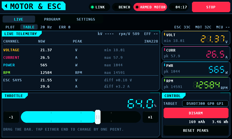
TABLE lists the four channels, each with its extreme. A channel nothing
answered for reads --.
With the INA228 enabled on SETUP under INTERFACES and answering (BENCH flag
bit 5), voltage, current and power are the INA228's: the means of the
coprocessor's last 50 ms window, read at 20 Hz, with the run's peaks from its
500 Hz samples. The heading names the source, INA228, and adds CLIPPED
while a current read the end of the part's range in the last window or since
the switch to ARMED: current and power, or their peaks, are then bounds and not values.
Under the channels, ESC SAYS lists the ESC's own telemetry voltage and
current from the SENSE page, and diff is the ESC's figure less the
INA228's. An ESC that reports a current it does not measure shows a
difference the size of the reading. An INA228 that stops answering during a
run leaves voltage, current and power empty to the end of that run; they do
not fall back to the ESC's figures. The peaks it measured in that run stay
shown, here and on the rail. Without the INA228, the channels are the
ESC's telemetry and ESC SAYS is not shown.
The mAh and Wh under ARM are the INA228's own while BENCH flag bit 6 is set: its charge and energy since the switch to ARMED, accumulated in the part at every conversion and read in 0.01 mAh and 0.01 Wh steps. The coprocessor takes the last run's totals and bit 6 off the bench page on the switch to ARMED, and the panel counts the first 100 ms of a run itself as well, so a page built before the switch cannot carry the last run's totals into this one. Without bit 6 the panel counts both from the current and power shown. When the INA228 stops answering mid-run, the count carries on from its last total and does not go back.
A run's CSV file has one row for every sample the panel takes, and no row without one:
- With the link up a sample is one answered read of the BENCH page. The panel polls every 50 ms plus the 5 ms pass of its control task that looks at the gate and the pass's own exchanges: 52.9 ms on average on one bench, about 19 rows per second. Other benches are not measured.
- With the link down a sample is one step of the model, every 50 ms.
- A sample is one row. With the INA3221 read through the window ring
(coprocessor protocol 4.11, CH1 enabled) a poll that brings more than one
50 ms window writes one row for each: the rows of one poll carry the same
time, the sample is in the last of them with the newest window, and the rows before it holdwindowand the channel columns and are empty otherwise. At a 53 ms poll one poll in 17 writes two rows. - Nothing else gates a row. A row the card's queue cannot take is dropped and counted, and the band says so at the run's end (see Logs).
time is the wall time since the switch to ARMED in seconds, written to 1 ms, and is
not a row count: the first row is not at 0, and a stretch without samples or
with dropped rows is a step in time of that length. The value keeps 1 ms
of resolution for the first 4.5 h of a run and 2 ms up to 9.1 h.
A file written by firmware 0.15.0 or older differs in two ways. Rows are
missing in stretches of up to 30 s after a servo command, and
time advances only with a written row, so it ends short of the run's
length and shows no gap. In such a file the window numbers, 50 ms apart,
give the spacing of the rows while the INA3221 is enabled.
time (s);voltage (V);current (A);power (W);rpm (rpm);esc (C);motor (C);charge (mAh);energy (Wh);ina voltage (V);ina current (A);esc current (A);window;ch1 current (A);ch1 max (A);ch1 voltage (V);ch2 current (A);ch2 max (A);ch2 voltage (V);ch3 current (A);ch3 max (A);ch3 voltage (V);source
voltage, current and power are what the screen shows. source is
measured on a row whose values a meter produced and model on a row the
panel's model produced (the MODELLED mark); a supply file has the same last
column. A file without the column ends at ch3 voltage or energy, and the
log viewer and the tools read both forms: source is a
text column and is never plotted. ina voltage and
ina current are the INA228's and are empty while it is not the source;
esc current is the ESC's own telemetry current, from the SENSE page while
the INA228 is the source and from the BENCH page otherwise, and empty when
the ESC reports none or the panel models the bench. A quantity nothing
measured is an empty cell. window and the nine channel columns are the
INA3221's 50 ms window -- per channel the mean and highest current and the
lowest bus voltage -- on the first row after the panel read it and on no
other, so each window is in the file once, under its number; a channel the
window has no readings of is empty, and so are CH1's current cells or its
voltage cell for a window that holds no sample of that quantity. With a
coprocessor of protocol 4.11 and
CH1 enabled every CH1 window is in the file while two reads lie at most
200 ms apart, and a step in window of more than 1 is a window that was
lost or a number the coprocessor skipped. A window taken while the bench
was SAFE is in no file. CH1's figures count a clipped sample at the end
of the range, 1.638 A on the 0.1 Ω shunt, and keep the sign of a negative
current. CH2 and CH3 are on the row of their window when the panel read
both pages within that window, and empty on a row the poll caught up. With
an older coprocessor, or with CH1 off, the columns hold the last window of
each read: a poll longer than 50 ms skips windows, 1 in 17 at 53 ms, and a
clipped sample is left out of the figures. The log viewer groups ina voltage,
ina current and esc current under INA228 and ESC, and the window's
columns under INA3221.

While the bench is ARMED, drag anywhere on the sweep to command a position. The solid arm is the measured position; the faint arm is the commanded position. The gap between them is the servo's own lag. The rings around the tip pulse while the servo is being driven. Lifting the finger does not let go: the screen keeps saying the last position every SERVO_HOLD_MS, so a servo stays where it was put. RELEASE, the button, is what returns the surfaces to centre -- and even that leaves the pins bound and driving, at the middle of their travel. A switch to SAFE, or leaving the screen, which switches to SAFE, is what stops the edges. With the rotary knob on, turning it moves the horn from where it is (the knob).
One finger drags the dial. A press by a second finger anywhere on the screen ends the drag, as it ends a drag on SPEED: the horn stays where it was commanded, and the dial follows again after a new press on it.
The screen drives the channels the binding marks as surfaces, not a fixed pin and not a fixed protocol. PPM's eight channels are surfaces too, so a bound PPM output moves with this screen exactly as a bound SERVO PWM one does. With no surface channel bound at all it commands nothing and no pin moves.
SPEED is the rate the bench may move the output, in degrees a second of the horn's travel, not a speed for the drawing alone. At 100% the command goes straight through and the servo moves at its own rate; below that the bench ramps the command in front of it, so 30% takes three times as long to cross as 90%. It applies to a held output as soon as it is changed. Without feedback the horn is drawn moving at the same rate, and at 100% at the command at once.
ARM before anything moves. ARM here switches the surfaces and a pulsing PROG PORT to ARMED; a throttle output sends no pulse (An arm for one role). While the bench is SAFE for the surfaces the coprocessor writes a pulse of length zero to every PWM pin, and the screen takes no position: the commanded value changes only while the servo follows it. The button is a two-second hold, the same gesture and the same fade as the one on MOTOR & ESC, and a press on it while ARMED switches to SAFE. Leaving the screen switches to SAFE and lets go of the pin: a screen that is not visible must not be holding a servo somewhere, or leaving the bench ARMED behind it.
What each control does while the bench is SAFE:
| Control | SAFE | ARMED |
|---|---|---|
| The dial | refused: no command, the horn and COMMANDED stay | commands the position under the finger |
| Rotary knob | refused; the turn is not kept | moves the horn from the commanded value |
| CENTRE | refused; drawn dimmed | commands PULSE CENTRE plus TRIM |
| SWEEP, PAUSE, PAUSED | refused; drawn dimmed | starts, pauses and resumes the sweep |
| RELEASE | sends the release; the value shown stays | centres the surfaces; the value shown becomes the rest |
| SPEED | set; sends nothing | set; a held position is sent again at the new rate |
| SETTINGS: TYPE, FRAME RATE, PULSE MIN, CENTRE and MAX, TRIM, TRAVEL, REVERSE | set; send nothing | set; a held position or the rest is sent again under them |
| SET, OUTPUT ON, OUTPUT OFF | as on SUPPLY | as on SUPPLY |
| START TEST | refused: ARM FIRST
|
starts the run after its hold |
While SAFE, the horn is drawn dimmed and the left card reads ARM FIRST. The
horn and COMMANDED show the position last driven; after a restart, PULSE
CENTRE. A pulse-width setting changed while SAFE changes the
microseconds COMMANDED shows for that angle, and TRAVEL does not clamp it.
From a DISARM the screen asks for, by the tap or by leaving, or a STOP while the
bench is ARMED, until the bench reports SAFE, the SAFE column holds as
well, and a sweep, a pause, a held position and a run of the automatic test
end where it is asked.
When the bench switches to ARMED, the commanded value becomes the rest the pins drive: the midpoint of the channel's endpoints, 1500 us for STANDARD PWM and 760 us for NARROW 760, without TRIM. Without feedback the horn is drawn there at once. The first drag or knob turn after a switch to ARMED starts from that value, whatever the screen showed before; a 1 % turn of the knob on STANDARD PWM asks for 1510 us. A type or pulse width changed while the bench is ARMED before the first position moves the rest, and the value with it.
A finger on the dial when the bench switches to ARMED, switches to SAFE or stops moves nothing until it lifts and presses again. A position, a sweep or a pause the screen has posted and the panel has not sent when the bench switches to SAFE or stops is not sent, and a knob turn in that state is withdrawn: the value returns to the one before the turn.
RELEASE while the bench is ARMED follows the rule of the switch to ARMED again. The pins go to the rest, and the commanded value becomes that rest: 1500 us for STANDARD PWM, 760 us for NARROW 760, without TRIM. The horn is drawn moving there at SPEED. A drag under way ends. A press on the dial drives the servo again, and the first knob turn counts from the rest: a 1 % turn on STANDARD PWM asks for 1510 us. The same holds for the release a run of the automatic test ends with, and for the one a changed type or pulse width sends on a resting bench. One command waits for each frame: of a position and a RELEASE made in the same frame the later is sent, and the value shown is that one's. A knob turn in a frame in which RELEASE waits is dropped.
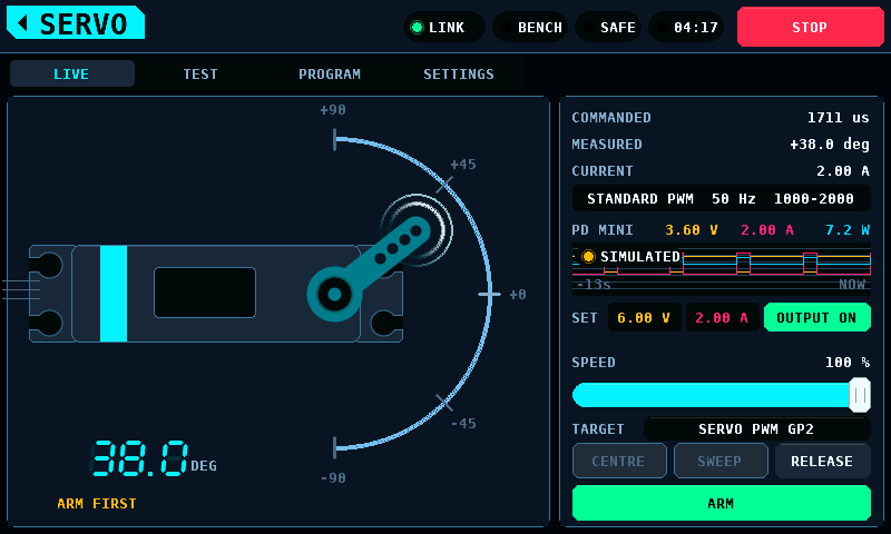
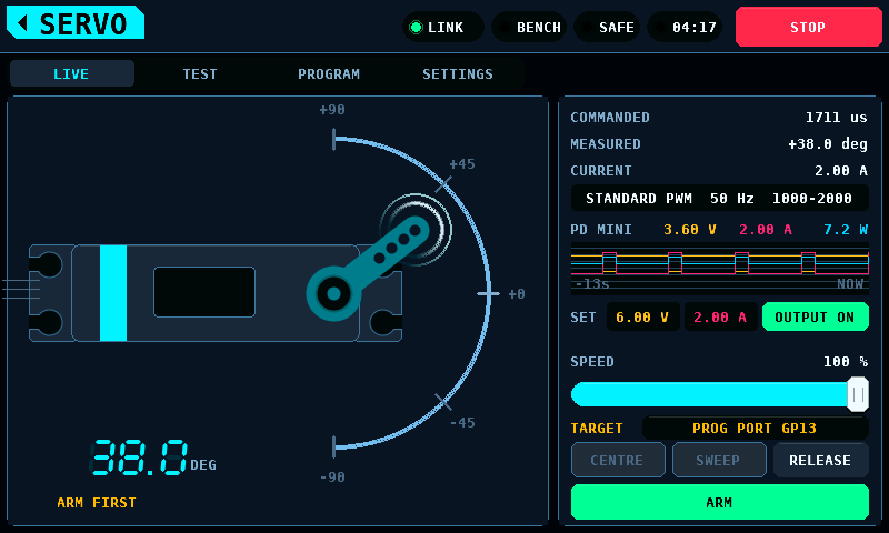
The right card shows what is commanded and measured, the type, frame rate and
pulse range in force -- in the danger colour while they are ones that can
destroy a servo not made for them -- and the servo rail as its meter reads
it: voltage, current and power on the line over the plot, plotted over the
last 13 s, and the current again in the CURRENT row. The type row reads
STANDARD PWM 50 Hz 1000-2000: the type, the frame rate and PULSE MIN to
PULSE MAX in microseconds, two spaces apart. The longest, a 13-character type
at 560 Hz with two 4-digit ends, takes 32 of the row's 33 characters, so the
range carries no unit. A pulse width typed in the settings reaches the row
at once.
| The servo rail's meter | Name on the line | CURRENT, the line and the plot show |
|---|---|---|
| INA3221 CH1 | INA3221 CH1 |
CH1's last 50 ms window: the mean current, the mean bus voltage at the load side of the shunt, and their product. One point of the plot per window, 20 a second |
| the PD mini | PD MINI |
the supply's last sample. One point per sample |
| the model, while no coprocessor answers | PD MINI |
the supply's last sample: the supply model's under the SIMULATION watermark, and no reading where SETUP INTERFACES enables the PD mini, which does not answer without the link |

The name stays PD MINI in both languages. While the PD mini is disabled on
SETUP under INTERFACES, the supply is the panel's model of it, as on SUPPLY:
then a MODELLED pill (SIMULIERT in German), 20 px high and 24 px plus the word
wide but at least 88 px (88 px for MODELLED, 96 px for SIMULIERT), sits
on the plot's top-left corner under the name, because the line beside the
name holds the three readings. The pill comes and goes with the model,
without a tap. With INA3221 CH1 as the meter the line names the INA3221 and
carries no pill, the supply's model or not.
Which meter it is is decided once per poll (the current monitors): the INA3221 1000 ms after its conditions hold, the PD mini from the first poll in which one fails.
-
A current is signed and shown in hundredths of an amp:
0.41 A,-0.02 A,-1.64 A. A reading that rounds to zero is0.00 A. The power on the line is signed in tenths of a watt. BesideINA3221 CH1the three readings have 60, 64 and 56 px, 7, 8 and 7 characters: a power of more than 7 characters in tenths,-100.0 Wand beyond or1000.0 Wand beyond, is shown in whole watts. -
A reading that did not arrive is
---in the CURRENT row,--on the line and a gap in the plot: no sample yet, a supply that does not answer, no window since the link came up, a window without samples of that quantity. -
A window in which a sample read an end of the INA3221's range, 1.638 A or -1.638 A on a 0.1 Ω shunt, shows its mean as it is, in the warning colour in the CURRENT row and on the line. The clipped samples count in that mean at the end of the range.

-
A link that goes down takes the INA3221's last window with it:
---and--until the meter changes or a window arrives over the link. -
The plot is emptied when the INA3221 becomes the meter and when it stops being it: the trace is of the meter the line names. Each window and each supply sample carries the meter of the poll that took it, so a reading taken before its meter became the rail's is no point of the trace, and none taken after is left out. The plot's scale starts at 0, and a negative current is drawn on its lower edge.
-
The CURRENT row's value is repainted when its digits or its colour change, and by itself.
The automatic test reads the supply whichever meter the rail has.
MEASURED is the horn's angle from the centre count while AS5600 is on in
SETUP, INTERFACES, the sensor answers and it detects its magnet: +38.0 deg,
tenths of a degree, -180.0 to +179.9, read 20 times a second. It is ---
while the sensor does not answer and while it reports no magnet (STATUS MD
clear): its count is no angle then. A magnet reported too weak or too strong
leaves the angle on show; the band says which. Where AS5600 is off the row
shows the feedback's angle. The commanded position beside it is the
pulse width in microseconds.
The supply is set and switched here too. The SET line under the plot holds SUPPLY's two set points, the voltage and the current limit, and its output switch. They are SUPPLY's, not a copy: a change on either screen is the change on both.
-
A tap on a set point opens the keypad over the left card. A value outside the caps is brought inside them, as on SUPPLY.
-
While the output is on, a typed set point waits for SUPPLY's question, OUTPUT IS ON, with APPLY and CANCEL, unless SUPPLY's SETTINGS, CONFIRM WHILE ON, KEYPAD is off. The question goes, unanswered, when the output goes off or on STOP. An APPLY tapped in the same frame as STOP applies nothing, though the supply reports the output off a sample later.
-
A voltage raised from 6.0 V or below to above it opens the warning HV SERVOS ONLY: standard servos are rated for 4.8 to 6.0 V, and above that only a servo specified as HV (high voltage) is within its rating; a standard servo above it can be destroyed immediately. The voltage is applied after HOLD TO APPLY is held for 2 s, the gesture of the profile warning; CANCEL drops it. STOP ends the hold. With the output on it replaces SUPPLY's question, and it stays if the output goes off. A voltage already above 6.0 V changes without it. A voltage set on SUPPLY does not open it.

-
OUTPUT ON is a two-second hold, OUTPUT OFF a tap, as on SUPPLY. STOP ends a hold under way. With a voltage set point above 6.0 V, wherever it was set, OUTPUT ON opens HV SERVOS ONLY instead, naming the voltage, and the output comes on only after HOLD TO APPLY is held for 2 s; the switch's own hold and a tap on APPLY switch nothing on. A set point that rises above 6.0 V during the ordinary hold -- on SUPPLY, or put back after a run -- is seen as the hold completes: HV SERVOS ONLY opens and nothing comes on. Leaving SERVO switches off an output SERVO switched on: by OUTPUT ON, by a test, or by the servo programmer's CONNECT. While the servo programmer holds a port the output stays on, as an OFF would end the session and cut a write under way; it goes off when the port lets go, unless SERVO is shown again first. An ON SERVO asked for that is on its way when the port takes the supply counts as switched on. An output SERVO did not switch on stays as it is. The servo programmer, the keypads and the questions belong to SERVO and are no leave. A press on OUTPUT OFF as the screen is left is sent as the OFF it was.
SWEEP drives the servo through a curve on the coprocessor, where its timing does not depend on the link: the TEST page's CURVE (square, sine or triangle), SPEED (0.05 to 5 cycles a second) and DWELL (the hold at each end), about PULSE CENTRE. RANGE is a share of the travel the servo may make: of TRAVEL, and of the nearer of PULSE MIN and MAX, so the sweep reaches neither end it may not. SPEED on the right card limits it as it limits a drag, and trim is not applied. The horn follows the same curve, computed on the panel and timed from when the coprocessor started its own. The panel draws only what the coprocessor is known to do: a sweep asked for, or resumed, is drawn once its start is acknowledged, and until then the horn stays where the output is. Without feedback it is then worked on from where the output was when the coprocessor began, along the curve at SPEED. Two taps on the sweep button that reach the screen in one frame, before the first one's command has left, cancel out: nothing is sent and the sweep goes on as it was.
PAUSE pauses it. While a sweep runs the button reads PAUSE in the accent
colour. A tap stops the sweep where the output has got to -- which SPEED can
leave behind the curve -- and holds it there; the button then reads PAUSED,
filled in the warning colour. The coprocessor does the holding (the link's
HOLD, SWEEP register 4), because only it knows exactly where that is;
without feedback the horn drawn on the panel is an estimate of it. The panel
repeats the hold every 100 ms (SERVO_HOLD_MS), so a pause outlasts the
coprocessor's 500 ms rule. A pause does not wait behind sweep writes already
on the wire. A tap on PAUSED carries the sweep on from the point of the
curve it was paused at: its place in a dwell and the ends it has reached go
on from there too, and the horn is drawn on from that phase. The phase is
the curve's when the coprocessor acknowledged the HOLD, not at the tap: the
curve runs on there for the exchange in between, and so the drawing runs
on too, at the SPEED in force at the tap, for at most 500 ms -- the longest
the coprocessor runs a sweep it has not heard. Without feedback the drawn
horn is then put where the output had got at the acknowledgement: the curve
to that phase, slewed as the drawing slews. A SPEED changed in between reaches the
coprocessor only with the resume. A tap on PAUSED leaves the horn where it
is until the resume is acknowledged; the panel then times the drawing from
the phase the coprocessor kept, as it timed the two acknowledgements, also
when the tap came before the HOLD's acknowledgement; that acknowledgement,
arriving after the tap, still moves the horn to where the coprocessor held
the output, and the resume goes on from there. The coprocessor
keeps the phase while it holds and resumes the curve (LINK_SV_RESUME,
protocol 4.6); the output slews from where it was held to the curve at
SPEED's rate, at once at 100 %, and is normally already there. A curve
changed on the TEST page while paused starts as a new sweep instead. A
coprocessor older than 4.6, or one that refuses the resume because its hold
has ended, starts the curve over from its beginning -- the centre for a
sine or a triangle, the first end for a square -- and the alert band says
so: coprocessor older than 4.6 -- the sweep starts over or coprocessor refused the resume -- the sweep starts over. So does PAUSED tapped while
the HOLD has gone unanswered, since the coprocessor may then be holding or
still running: the pause went unanswered -- the sweep starts over. A
PAUSED tapped before a HOLD that the panel then lets go of (below) starts
nothing: the pause ends with that HOLD.

A hold the link left unrepeated for 500 ms has been let go at the far end, so the panel releases the surfaces to their centre and the horn goes there. So does a HOLD answered only at a retry, or after longer than 500 ms: the coprocessor may have let it go and held again elsewhere, so where it holds is not known on the panel, and the pause ends rather than keep an angle a later change of profile would send to the servo. The link going ends a sweep or a pause too, and the horn is drawn at rest, as the coprocessor rests the surfaces 500 ms after the last write it heard; no sweep or hold asked for before is sent when the link comes back, and the next tap starts a sweep. A finger on the dial, CENTRE, RELEASE, STOP, a switch to SAFE and leaving the screen end a sweep, running or paused, and the button reads SWEEP again. A changed type, frame rate, pulse, trim, travel or reverse ends a pause too, and the servo is held at the paused angle as a position. With feedback the paused angle is the one the servo last reported, which it can still be moving to after the tap; without feedback it is the drawn estimate at the acknowledgement. A changed SPEED keeps the pause; the resume runs at the new SPEED. Touch events going missing pause a running sweep as PAUSE would. A changed setting starts a running sweep over with the new curve, drawn from when the coprocessor acknowledges it; until then the old curve is drawn on, as the coprocessor runs it, under the pulses and TRAVEL it was sent with. Each acknowledgement is matched to the command it answers: a SPEED or curve changed while a start waits does not let the earlier command's acknowledgement draw the newer one. A changed profile or frame rate goes with it at once. SWEEP is offered while the bench is ARMED, with a surface bound and the link up, and a coprocessor speaking protocol 4.2; greyed otherwise; the coprocessor stops a sweep the panel has not repeated for 500 ms and leaves each surface where its output has got to.
SPEED LIMITS THE SWEEP replaces SPEED's label on the right card, in the warning colour, while SPEED is slower than the fastest change the curve asks for. SPEED then shapes the motion instead of CURVE: a square, a sine and a triangle all move as ramps at SPEED's rate and look alike, and the output can turn back before it reaches an end. The line follows the settings, so it shows before SWEEP is pressed as well as while a sweep runs. Raise SPEED, or lower the TEST page's SPEED (the rate in Hz) or RANGE, to clear it. A square jumps between its ends, so it shows at every SPEED below 100 %. With the TEST page's defaults (sine, 0.5 Hz, RANGE 80 %) and TRAVEL +/-90 deg it clears at SPEED 63 %, and for a triangle at 40 %. Servo procedures gives the rule.

START TEST runs the automatic test on the TEST page: the servo stepped
through the supply voltages chosen there, its current measured at rest,
moving and holding, its travel timed, and the voltage at which it stops
moving. Servo procedures gives the method and the
files. START TEST needs the bench in ARMED and a supply that answers; the line
under it says ARM FIRST, NO STEP CHOSEN, SUPPLY NOT ANSWERING, RANGE TOO
SMALL (the ends RANGE and TRAVEL give land on PULSE CENTRE), A STEP IS
OUTSIDE THE CAPS (a chosen step above the voltage cap in force, checked
before any warning opens) or LAST REPORT STILL WRITING, and follows the
bench and the settings as they change. A third line, across the card under
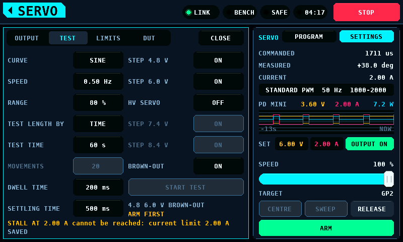
both columns, says when no reading can pass STALL AT: STALL AT 2.00 A cannot be reached: current limit 2.00 A while STALL AT is at or above the
SET line's current limit, else STALL AT 2.00 A cannot be reached: INA3221 range 1.638 A while the INA3221 is the rail's meter and STALL AT is at or
above its range. START TEST stays open: see
Stall and constant current.
It is a two-second hold,
the gesture OUTPUT ON uses, because a run switches the supply on and moves
the servo. With HV SERVO on and a step above 6.0 V chosen, a tap opens HV
SERVOS ONLY instead, naming the highest step, and the run starts only after
its HOLD TO APPLY is held for 2 s. HV SERVO is for the session: every restart
turns it off.
The settings close as the run starts, and its step and phase show at the top
of the left card, with the meter the run reads beside STOP TEST: PD mini,
INA3221 CH1 or MODEL. It is the servo rail's meter at START TEST, and
the run reads it to its end (The meter). The run owns
the servo and SUPPLY's set points and switch until it ends. It ends early, the output switched off and the servo released
to its centre, on STOP TEST (on the left card or the TEST page), STOP, a
switch to SAFE, the link going, leaving the screen, a finger on the dial, CENTRE,
SWEEP, RELEASE, a tap on a set point, a change to the servo's type, pulses,
trim, travel, reverse or SPEED, touch events going missing, and on the
supply: see the list. Once a run is over, whichever screen is up, SUPPLY's set points go back to
what they were before it. That waits until the run's OFF has been sent, a
reading taken after that in which the supply itself reports the output off
-- not the panel's request, which the PD mini follows a link exchange and a
module transaction later -- no ON is on its way and
OUTPUT ON is not being held on SERVO or SUPPLY. Set points changed after
the run ended are
left as they are.

The result stays on the left card until CLOSE: PASS, FAIL or ABORTED and
why, the longest travel time and the highest holding current, and the files
the card took: BENCHnnn.CSV, and + .TXT once the card has taken the
report whole.

A run that read the INA3221's windows names it there, as the line over the plot does:

START LIMIT RUN runs the limit search on the LIMITS page: the servo
stepped outward in 10 us steps until its current shows the linkage bound,
and, with LIMIT RUN on SEARCH+PROG, a KST or Chaservo servo's LEFT ANGLE
and RIGHT ANGLE lowered until neither end binds. On a SERVO PWM pin the
search runs from PULSE CENTRE to PULSE MIN and PULSE MAX; on PROG PORT a
read session comes first, and the search runs from the servo's NEUTRAL to
its own PULSE LOWER and PULSE UPPER. Servo procedures
gives the method, the protections and the report. It is a 2 s hold while
the bench is ARMED and the INA3221 is the servo rail's meter; the line
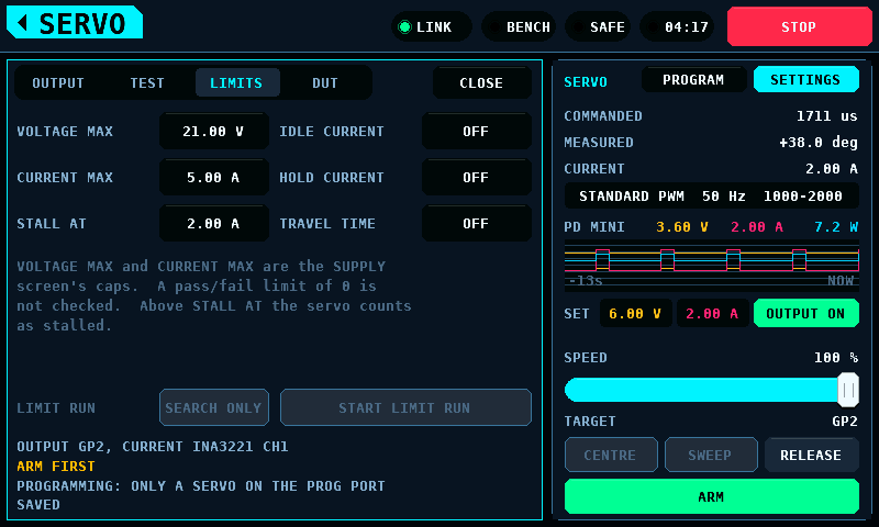
under it names the output it drives and the meter, OUTPUT PROG PORT GP13, CURRENT INA3221 CH1, and the next line says why it cannot start. The
settings close as the run starts. Its box on the left card shows the
values written of 8, the phase with the side and the pulse, and the output
it drives, with STOP RUN; after the run, the verdict, the values or the
ends, and BENCHnnn.TXT until CLOSE. The run switches the bench to SAFE and
to ARMED itself for each write; the operator's STOP, SAFE or any of the
automatic test's reasons end it with the output off.


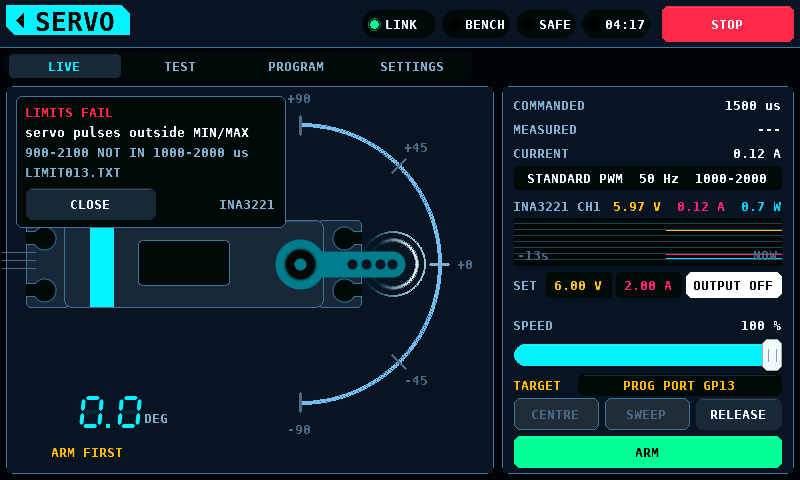
PROGRAM, beside SETTINGS, opens the programmer for KST and Chaservo servos
over the left card. It takes the coprocessor's programming port, GP13 on
pad 17 by default, out of PWM (pulse-width modulation) and reads and writes
the servo's settings on its signal wire. It connects only with PWM TARGET
on the DUT page set to PROG PORT; with OUTPUTS it shows Programming needs the programming port. and CONNECT is locked. While it holds the port the
overlay stays open and SETTINGS is off; ARM is drawn disabled and takes no
press, CENTRE, RELEASE and STOP work, and COMMANDED reads ---: the
tester sends no pulse to the port. In PWM with a PD mini answering, the
programmer's PORT row names the voltage and the current limit CONNECT sets,
PORT 5.0 V 1000 mA. The set points and OUTPUT ON of
the SET row and of the SUPPLY screen are dimmed and take no press for as
long; OUTPUT OFF works.
It leaves programming without a cycle of the servo's supply. Whether a KST
servo follows PWM while in programming mode is not measured.
Servo programmer for KST and Chaservo servos
describes it.
SETTINGS, at the top of the right card, opens the servo's settings over the left card. ARM, CENTRE, RELEASE and STOP stay where they are and work. A value opens the keypad, a list opens a list, a switch flips on the tap, and the name opens a keyboard.

| Page | Setting | What it does |
|---|---|---|
| OUTPUT | TYPE | the servo profile: STANDARD PWM, NARROW 760, WIDE, HELI CYCLIC or HELI TAIL 760 |
| OUTPUT | FRAME RATE | how often a pulse is sent; the type's list, or CUSTOM on the keypad |
| OUTPUT | PULSE MIN, CENTRE, MAX | the pulse widths the travel maps onto, 400 to 2500 us: -90 deg is MIN, 0 is CENTRE, +90 deg is MAX, and RELEASE rests at CENTRE. An end lies no further from CENTRE than CENTRE lies from 400 us or 2500 us |
| OUTPUT | TRIM | added to the centre, 5 us a step, up to 200 us either way |
| OUTPUT | TRAVEL | how far the horn may go each way, 10 to 90 degrees |
| OUTPUT | REVERSE | the direction the horn's angle maps onto the pulse |
| TEST | CURVE, SPEED, RANGE | the movement of SWEEP: square, sine or triangle, 0.05 to 5 Hz, 10 to 100 % of the travel. The automatic test moves in steps between the ends RANGE gives |
| TEST | LENGTH BY, TEST TIME, MOVEMENTS | how long each supply step runs: a time, or a number of movements |
| TEST | DWELL, SETTLE | held at each end; waited after a supply step before measuring |
| TEST | STEP 4.8 / 6.0 / 7.4 / 8.4 V, BROWN-OUT | the supply steps, and the brown-out run from 5.0 V down; 7.4 and 8.4 V run only with HV SERVO on |
| TEST | HV SERVO | adds the 7.4 and 8.4 V steps, off by default and at every restart; a run with them starts only through HV SERVOS ONLY |
| TEST | START TEST | the automatic test: a 2 s hold while the bench is ARMED; STOP TEST while it runs |
| LIMITS | VOLTAGE MAX, CURRENT MAX | the SUPPLY screen's caps, the same settings |
| LIMITS | STALL AT | above this current the servo counts as stalled |
| LIMITS | IDLE CURRENT, HOLD CURRENT, TRAVEL TIME | pass/fail limits; 0 is not checked |
| LIMITS | LIMIT RUN | SEARCH ONLY or SEARCH+PROG, a tap switches; SEARCH+PROG is offered for a servo on the programming port only, and the row reads SEARCH ONLY with the reason under START LIMIT RUN otherwise. For the session |
| LIMITS | SERVO PULSES | KEEP or 1000-2000, a tap switches; shown with PWM TARGET on PROG PORT only. 1000-2000 writes the servo's PULSE LOWER and PULSE UPPER to 1000.0 and 2000.0 us in the run's read session, before the search. KEEP by default; for the session |
| LIMITS | START LIMIT RUN | the limit search: a 2 s hold while the bench is ARMED and the INA3221 is the servo rail's meter; STOP RUN while it runs |
| DUT | NAME | the device under test, up to 23 characters, for the report |
| DUT | REPORT | a text report beside each test's log |
| DUT | AS5600 | the output encoder, the same setting as SETUP, INTERFACES, AS5600: adds the horn's angle to the MEASURED row and to a run's CSV and report (Servo) |
| DUT | ENC CENTRE | a tap takes the live count as the centre, with the servo at its neutral, and sets nothing without a reading from the current link (none after a link loss until a new one arrives) or while the sensor reports no magnet; the row shows the stored count, 0 to 4095, and is dimmed while AS5600 is off. The same setting as SETUP, INTERFACES, AS5600 centre |
| DUT | PWM TARGET | what the tester drives: OUTPUTS, the pins bound as SERVO PWM, or PROG PORT, the coprocessor's programming port. PROG PORT is what the programmer needs. Locked while ARMED, during a sweep or a test, and while the programmer holds the port (the target) |
| DUT | PORT PWM | the pulse on the programming port, ON or OFF. Locked with PWM TARGET on OUTPUTS; ON under the rule of PWM TARGET, OFF ARMED or not but not during a sweep or a test, and neither while the programmer holds the port |
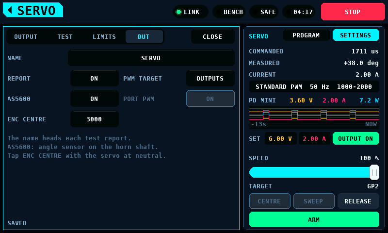
The active PWM TARGET is the TARGET row of the right card, between SPEED and
CENTRE. The right card stays in sight under the settings, their keypads and
the servo programmer, so the row names the pin while any of them covers the
left card. With OUTPUTS the row names the GPIOs bound as SERVO PWM in the
binding the tester drives: GP4, GP2 GP4; as many pins as fit the 23
characters of the value, then +N: 6 pins from GP40 on read
GP40 GP41 GP42 GP43 +2. The value is right-aligned beside the label. The row is in the warning colour, label and value, with no
such pin (NO SERVO PWM PIN) and before a binding has been read
(PINS NOT READ). With PROG PORT the row reads PROG PORT GP13 in the
warning colour; the pin is the GPIO the coprocessor reports for the
programming port. The tester's commands then do not reach the SERVO PWM
outputs; while the bank is ARMED they hold their rest pulse, the centre
between their endpoints. A port target without a usable pin (none, refused
at start, or a port the coprocessor does not have) reads PROG PORT, also in
the warning colour: the commands go to the port all the same. With PORT PWM
off the port renders no pulse, and the row adds PWM OFF:
PROG PORT GP13 PWM OFF, 22 characters with a two-digit pin. Two states name
no target, both in the warning colour, and the tester sends no command in
either: NO LINK while no coprocessor answers, and NOT KNOWN while the
coprocessor's programming-port page has not been read since the link came
up, a write to it was not acknowledged, or a read of it went unanswered.
While the servo programmer holds the port, the row does not change: it keeps
naming the target the coprocessor holds, a port or the outputs; the
programmer drives the port and the tester sends nothing. The page is read
every 500 ms. A coprocessor without that page (protocol older than 4.13) has
the standard outputs as target. The row follows the target the coprocessor
holds, not the setting: a PWM TARGET change waits for a quiet bench and
reaches the row once the coprocessor has taken it.
| Type | Centre | Travel | Frame rates |
|---|---|---|---|
| STANDARD PWM | 1500 us | 1000-2000 us | 50, 60, 100, 150, 200, 250, 300, 333 Hz |
| NARROW 760 | 760 us | 660-860 us | as STANDARD PWM |
| WIDE | 1500 us | 800-2200 us | as STANDARD PWM, up to 312 Hz |
| HELI CYCLIC | 1520 us | 820-2220 us | 50, 120, 200, 333 Hz |
| HELI TAIL 760 | 760 us | 410-1110 us | 200, 333, 560 Hz |
A pulse needs a pause before the next frame. STANDARD PWM, NARROW 760 and WIDE keep at least 1 ms between pulses, so their fastest rate is 1 / (longest pulse + 1 ms): 333 Hz for 2000 us. The heli profiles run at Rotorflight's rates for digital cyclic and narrow-band tail servos, with at least 0.5 ms between pulses. A frame rate the pulses leave no pause for is refused, and a longer PULSE MAX is refused at a rate it does not fit. The pause is kept after the longest pulse the coprocessor can render, the top of the range a command carries: PULSE MAX, or past it when CENTRE is off the middle, by as much as CENTRE lies nearer MAX than MIN. So a CENTRE that would push that top past the rate's pause is refused too.
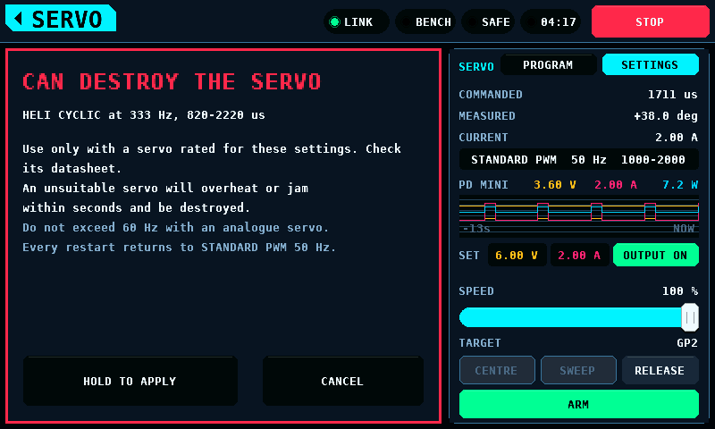
A heli type, or any frame rate above 60 Hz, can destroy a servo that is not made for it. Choosing one opens a warning in the danger colour that names what is chosen and what it does to a servo not made for it; it is applied only after HOLD TO APPLY has been held for 2 s. CANCEL, a finger that slides off, a touch loss and leaving the screen apply nothing. The type and frame rate in force stay red on the right card, and every restart goes back to STANDARD PWM at 50 Hz: a servo plugged in after a restart never meets a rate meant for another one.
The frame rate reaches the pins through the coprocessor's SERVO page (protocol 4.1). It applies to the PWM TARGET alone. With OUTPUTS, the standard servo ports, as target that is every PWM output whose first channel is a surface; a PPM output keeps its own frame. With PROG PORT as target it is the programming port's pin, and every slot keeps its own rate (protocol 4.19). Every other programming port runs at 50 Hz. A port whose pin shares its PWM slice with another programming port's pin runs at 50 Hz only: the RP2350 gives both pins of a slice one divider and one wrap, so a faster rate there is refused. A change of PWM TARGET puts the rate back to 0, each output at its own rate, and the screen sends its rate again with the next position. It goes with every held position, and a profile changed while the servo rests ARMED restates the rest with it; one changed while a switch to ARMED is on its way is the one that switch uses. A faster rate goes after the pulse widths, once all of them have landed; any other rate goes before them, and nothing wider goes out until it has landed, so the pins never carry a fast rate with a slower profile's wider pulses. The OUTPUT page says what became of it:
| Note | Meaning |
|---|---|
| In force | the rate runs on the target the coprocessor holds, named from its PROG page: In force: OUTPUTS run at 330 Hz. or In force: PROG PORT GP13 runs at 330 Hz. The note is in the warning colour while that target differs from the PWM TARGET setting (second line The PWM TARGET setting is not in force.; PROG PORT with no pin bound to the port leaves OUTPUTS the target), while the port target has no pin, while PORT PWM is OFF (PORT PWM is OFF: the port renders no pulse.) and while the target is not known. Against a coprocessor before protocol 4.19 the note reads "every PWM surface runs at": such a coprocessor runs every PWM surface at the rate, whatever the PWM TARGET. With no link both read No link: the rate in force is not known. in the warning colour: a coprocessor restarted while the link is down runs every pin at its own rate again |
| The rate goes with the next position | not written yet |
| REFUSED | a pulse of the target -- a surface, or the programming port while its pulse is on -- is longer than the frame at that rate, or a target pin shares a PWM slice with an output at another rate; the pins keep the rate they had |
| This coprocessor takes no frame rate | protocol 4.0: every PWM output runs at its binding's 50 Hz |
A coprocessor restart, and every binding written on OUTPUTS, put each slot
back at its own rate, 50 Hz for a servo; the screen sends its rate again with
its next position, against the binding then in force. A binding is not
written while the reset to each slot's own rate goes unanswered (OUTPUTS says
NO LINK) or is refused (REFUSED), and the bench
does not switch to ARMED, from any screen, while the rate the PWM TARGET runs at is not
known: the switch to ARMED is refused with servo frame rate not known -- arm again, and
a switch to ARMED made while the link was down reaches the coprocessor only once the
reset has landed.
The OUTPUT settings and HV SERVO are kept for the session; the rest of the TEST, LIMITS and DUT settings are kept in NVS (non-volatile storage) and written as on SUPPLY.

Current limitations:
- Until the screen sends a position, the pins run at the rate the SERVO page holds, which after a restart or a new binding is 50 Hz.
- On the panel's supply model the automatic test's currents are the model's load, not the servo's: a run there measures the model. What is not measured.
- The supply on the right card is SUPPLY's: the PD mini when SETUP enables it, the panel's model otherwise, whose voltage, current and power are simulated, not measured.
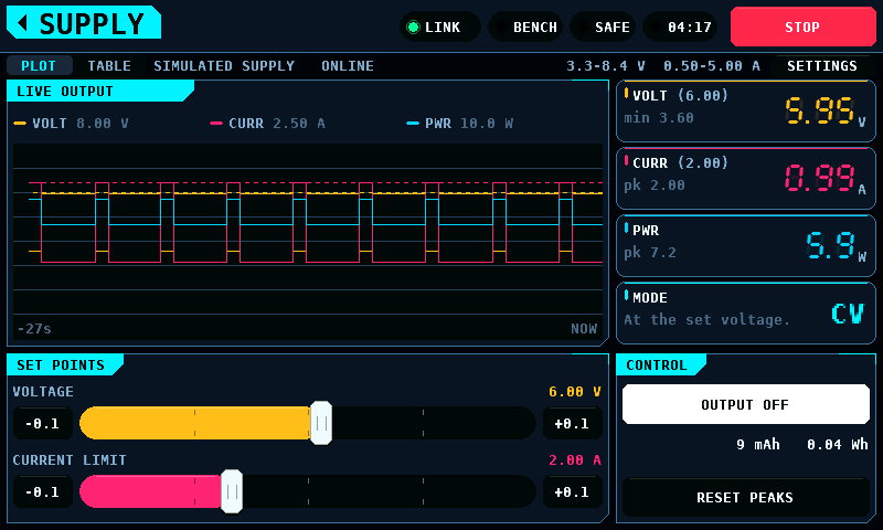
Sets, switches and records a programmable supply: the PD mini, a USB-PD (USB
Power Delivery) trigger controlled over a UART (universal asynchronous
receiver-transmitter). The coprocessor drives it on a PIO (programmable
input/output) UART on two of its pins, through the SUPPLY link page
(protocol 4.3). The panel writes the page and reads it every 100 ms. With
the PD mini enabled on SETUP under INTERFACES, the header names the module
and the coprocessor's UART pins that carry it, PD MINI TX GP12 RX GP13,
from the PD mini TX and PD mini RX settings. With either pin not set the
header says PD MINI NO PINS. With the PD mini disabled, the panel runs a model of a supply in its place: the header
says SUPPLY MODEL and the menu tile is marked MODELLED.
The layout is the one MOTOR & ESC uses. The plot shows voltage, current and power over the last 27 s. The rail shows the readings, the run's lowest voltage and its highest current and power. MODE says which set point the supply holds: CV (constant voltage) at the set voltage, or CC (constant current) at the current limit. CC is drawn in the warning colour: a supply in CC is not giving the load the voltage it was set to.
A set point is shown beside its reading. VOLT and CURR carry it in brackets after the label, and the plot draws it as a dashed line in the reading's colour, on the reading's scale. TABLE lists both. The bracketed value is the set point the supply reports holding; while it does not answer, the one the screen holds.
| Set point | Model | PD mini | Buttons |
|---|---|---|---|
| VOLTAGE | 3.3 to 21 V, 20 mV steps | 1 to 20 V, 10 mV steps | 0.1 V |
| CURRENT LIMIT | 0.5 to 5 A, 50 mA steps | 0.05 to 3 A, 10 mA steps | 0.1 A |
The model's ranges are a USB-PD PPS (Programmable Power Supply) source's widest profile, 3.3 to 21 V at up to 5 A. The PD mini's are from the vendor's page, not measured. The PD mini is a buck converter and gives no more than it is fed: its voltage is also capped 0.7 V under the input voltage it reports, so a 5 V input voltage allows at most 4.3 V. An input voltage under 1.7 V leaves the 1 V minimum, which the screen shows as the cap, and one under 1.5 V holds the output off; until the input voltage is read the cap is 20 V. A set point over the input voltage puts the module into ERR until it is power cycled; the margin it needs is not measured. The cap lies 0.2 V above the line the output is cut at (see below), so the input voltage can drop 0.2 V under load before a set point at the cap is cut. Both are narrowed by the caps in SETTINGS, and the sliders follow the supply in use. A tap on a track sets the value under the finger.
A tap on the VOLT or CURR card, or on a set point's value, opens a keypad over the left column. It shows the range in the title row and the current value faint until a digit is typed. OK takes a value inside the range, rounded to the supply's step; a value outside it is refused and the range turns to the warning colour. OK with nothing typed, and CANCEL, leave the set point as it was.

A change to a live output asks first. While the output is on, a new set point from the slider or its step buttons, or from the keypad, opens a question that names the change. APPLY gives it to the supply; CANCEL drops it and the slider goes back. A drag asks once, on the release, and the supply holds the old set point until then. With the output off nothing is asked. STOP closes the question unanswered: an APPLY tapped in the same frame (about 50 ms) as STOP applies nothing. SETTINGS switches the question off for the slider and for the keypad separately.

OUTPUT ON is a two-second hold, the gesture and the fade ARM uses. OUTPUT OFF is a tap. STOP switches the output off on every screen. So does every other stop the bench counts -- touch that stops answering, an ON whose touch events went missing before a whole frame saw the output on, and the coprocessor refusing to stay ARMED -- and a supply that stops answering, and a trip. The output stays off until it is switched on again. Leaving the screen switches off an output SUPPLY switched on: one reported on, or an ON on its way. SERVO and ESC STICK do the same for the output each switched on, so an output is on only while the screen that switched it on is shown. The exception: an output SERVO switched on stays on after SERVO is left while the servo programmer holds its port, until the port lets go (see SERVO). A servo is powered from SERVO and an ESC from ESC STICK. MOTOR & ESC switches no supply; an ESC run there is powered from its own source. An output another screen switched on stays as it is when SUPPLY is left. The keypad, the HV question and the other overlays of SUPPLY are no leave. The link-lost screen, which has no STOP, does not open while the output is on.
With the PD mini, an OFF goes to the SUPPLY page before anything else
the panel owes it, and the coprocessor switches the output off itself when
the panel's heartbeat stops. An enabled PD mini reads NOT ANSWERING while no
coprocessor that speaks protocol 4.3 answers, or while the page's readings
are older than 1500 ms; an output that is on is switched off then. A page
that answers while the module's reading count (SAMPLES) stands -- a display
read that fails while the other reads answer -- keeps ONLINE: after
1500 ms without a new reading the voltage, current and power cards show
dashes and no trip, peak or total takes a reading, and after 3000 ms (SUPPLY_LINK_BLIND_MS) an
output that is on is switched off and the band says
supply sends no readings -- output off. A set point changed faster than
the module takes it -- the slider dragged with SLIDER AND STEPS off, about
one new set point every 50 ms -- does not hold the readings back: a reading
400 ms past its due (PDMINI_POLL_LATE_MS) goes before the next set-point
write, one at a time with another transaction between two; the state read,
and the input voltage read before a write, may also follow another reading straight
away. With a module that answers at once, the display is then read about
500 ms after the last display read and the output state about 900 ms after
the last state read, each with up to two transactions more. An output the
module switches on while it is off on the panel, or switches off itself, is
seen during the drag. The input voltage is read before a set-point write or an ON
only when one is waiting, and not between the reads for an ON. Set points
and an ON reach a module that answers up to 390 ms late (the driver waits
400 ms; host model, 40 start phases): one set point within 2.5 s; an ON
within 3.6 s when the set points are already written, up to 7.5 s when it
is asked right after a set point change or a drag; a module switching its
output itself seen within 2.1 s during a drag. An output the module
switches on while OFF is asked is switched off about 500 ms later with a
module that answers at once, up to 1.8 s later at rest and up to 2.1 s
during a drag with one that answers up to 390 ms late. The real module's
reply time is not measured.
Current limitation: a module that answers late stretches the 500 ms of the
state and input voltage reads, as each transaction takes its reply time. At rest
the input voltage is read 850 ms apart at 100 ms late, 1.3 s apart at 200 ms and
2.5 s apart at 390 ms; the state up to 1.5 s apart.
Current limitation: with a module answering 279 ms or more late and the
slider dragged, the display is read only 3.7 s to 5.0 s after the last
display read (5.0 s at 390 ms), past SUPPLY_LINK_BLIND_MS; an output that
is on is switched off and the band says
supply sends no readings -- output off. The panel reads the page every
100 ms, which adds up to 100 ms to the gap it sees: from 263 ms late the
driver's gap is over 2.9 s, so the cut is possible from 263 ms. At rest the
display read stands up to 2.5 s at 390 ms. It stands over 1.4 s from
259 ms late and 1.5 s from 279 ms, so the cards can show dashes from about
260 ms. The
output is also switched off, with a line in the band, when the coprocessor
refuses an ON (no heartbeat) or lets one go (its heartbeat stopped, or it
started again). The output is switched off too, and not on
again until a new hold, when the module switches it off itself -- its
overcurrent protection or its button. The band also says when the pins are
refused, when the output would not switch, and when the set points would not
take. A pin or baud change, and enabling or disabling the PD mini, switch the
output off.
A sagging input voltage switches the PD mini off. While the output is on, the
coprocessor reads the input voltage of the module every 500 ms with a module that
answers at once, and further apart with one that answers late (see above).
When the input voltage reads under the set point plus 0.5 V on 2 reads in a
row, it switches the output off at once, and the band names the input voltage
and the set point, for example
PD mini input voltage 6.18 V under set 6.00 V + 0.5 V -- output off. From the
sag to the cut takes about 1.0 s with a module that answers at once.
Current limitation: with one that answers late it takes 1.7 s at 100 ms
late, 1.9 s at 200 ms and up to 4.7 s up to 390 ms (host model). The
output stays off until a new hold. An input voltage reading under 1.5 V leaves no
room for the lowest set point, 1.0 V: the ON is not written, and the band
shows the same message. One low reading switches nothing, and a
read that fails neither counts nor clears. While the output is on, its set
point is not lowered to follow a falling input voltage. The rule is chosen without
a bench measurement: whether a live module goes to ERR when its input voltage
sags is not measured, so the rule may cut a run that would have survived.
OUTPUT ON and OFF, RESET PEAKS and the readings stay live under the keypad, the question and SETTINGS. One finger at a time: while one holds a control, a second finger does nothing anywhere on the screen.
SETTINGS, at the right of the strip above both columns, opens the supply's settings over the left column. Each is kept in the panel's NVS (non-volatile storage) and survives a restart. A value opens the keypad; a switch flips on the tap. Every change is written at the next frame the bench is SAFE with no switch to ARMED waiting, the supply's output is off with no ON queued and the board's drawing is not being fetched or kept, and with it any change on SETUP that was not saved: a flash write stalls both cores, OUTPUT OFF and the trips included. The bottom line says SAVED, SAVE WAITING, NOT SAVED (the write was refused), or SETUP CHANGES NOT SAVED: a change made on SETUP and left without SAVE, which nothing writes until SAVE there or a change here asks for it.

| Setting | Range | Default | What it does |
|---|---|---|---|
| VOLTAGE MAX | 3.3 to 21 V | 21.00 V | the highest voltage a set point takes |
| CURRENT MAX | 0.5 to 5 A | 5.00 A | the highest current limit a set point takes |
| START VOLTAGE | up to VOLTAGE MAX | 6.00 V | the voltage set point after a restart |
| START CURRENT | up to CURRENT MAX | 2.00 A | the current limit after a restart |
| CURRENT TRIP | 0 to 5 A | OFF | output off once the current has been over it for TRIP TIME |
| VOLTAGE TRIP | 0 to 21 V | OFF | output off once the voltage has been over it for TRIP TIME |
| TRIP TIME | 0 to 5000 ms | 100 ms | how long a reading is over a trip before it fires |
| SLIDER AND STEPS | ON, OFF | ON | ask before the slider changes a live output |
| KEYPAD | ON, OFF | ON | ask before the keypad changes a live output |
A cap lowered under a set point brings the set point down to it at once, and a start value with it. A typed value goes onto the setting's step the safe way: a cap rounds down, so 12.01 V allows 12.00 V, and a trip typed above 0 is at least one step, never OFF. A trip of 0 is off. The time over a trip counts from the first reading over it. A reading under its trip starts the count again; a reading that did not arrive leaves it where it was. A trip switches the output off, MODE shows TRIP until the output is switched on again, and the band says which trip fired. The supply holds its current limit in CC, so a current trip at or above CURRENT LIMIT does not fire; set it below the limit to switch off a load that draws too much for too long.
The output stays off at a restart, whatever the start values.
With the PD mini as the supply, SETTINGS also offers RESET PD MINI. It switches the output off and restarts the module (its SYSTEM_RESET command), for a module that shows ERR -- a set point over its input voltage puts it there -- without unplugging it. The module is asked who it is again about 1 s later. Whether a restart clears every ERR is not measured. A coprocessor older than protocol 4.4 has no reset: the output goes off and the band says so.
A run is one switch-on of the output. The plot clears when the output comes on and holds the run after it goes off. The mAh and Wh under the switch count the run from the readings shown, each step capped at 1 s. RESET PEAKS starts the lowest and highest values again from the current reading.
A run is recorded to a BENCHnnn.CSV of its own, one row every 50 ms:
time (s);set (V);voltage (V);limit (A);current (A);power (W);mode;charge (mAh);energy (Wh);source
A reading that did not arrive is an empty cell. mode is CV, CC or OFF, and
empty while the supply does not answer. source is measured for the PD mini's
readings and model for the panel's model. The bench takes the log: switching to ARMED during
a supply run ends that run's file, and an output still on at the switch to SAFE starts
a new file. That file's charge and energy go on from the totals counted since
the output came on, as the screen's do, so its first row does not start at 0. The supply is stepped and logged on its own 50 ms cadence while
the control task waits on the link, so an unanswered coprocessor does not thin
out the supply's plot or its log.
The model is a 6 ohm load with a 1.4 A burst for 0.6 s every 3 s, behind a 0.05 ohm source resistance. At the starting set points, 6.00 V and 2.00 A, the burst takes it into CC. Its readings are not measured and nothing on the bench is powered.
The PD mini's wiring -- PD mini, PD mini TX, PD mini RX and PD mini baud -- is
on SETUP under INTERFACES. TX and RX are coprocessor GPIO numbers: TX goes to
the module's DM, RX comes from its DP. The coprocessor refuses a pin that is
reserved, bound to an output or the other pin. Once the module has
answered, a change waits for a state read of the module sent after it, at
most about 1.2 s, and is taken only if that read shows the output off: the
module can switch itself on between two state reads, by its button
or its AUTO OUT setting, and new pins would leave it no OFF path. A read
that shows the output on, or fails, refuses the change, and the band says
PD mini wiring refused -- its output may be on. A refused change is not
written again until the wiring changes in SETUP. PD mini baud is the module's
own UART Baudrate setting: 9600, 19200 (as shipped), 38400, 57600,
115200, 230400 or 460800 baud, or AUTO. AUTO, the default, lets the
coprocessor find it: it tries each of the 7 rates, one a second. The
SUPPLY header shows the rate in use after ONLINE, e.g. ONLINE 38400, with
AUTO and with a fixed rate alike.

Sixteen channels, each with about 1.7 s of history (118 samples) and a bar for its current value. CH17 and CH18 are the two digital channels. A glitch is a spike in one lane; a dropout is a notch across all sixteen at the same instant.
No firmware feeds this screen yet (see Receiver buses); it shows SILENT.
The state block shows one of SILENT, FAILSAFE, FRAME LOST and LIVE, with one line of explanation:

In FAILSAFE the receiver is sending well-formed values it has generated itself; every trace is drawn red. Treat FAILSAFE as a stop, not as sixteen valid channels. Receiver buses describes the states.
The sequence is: device class, protocol, connect. ESC STICK, the third class, lists ESC profiles instead of protocols and programs an ESC through its throttle-stick menu; it has a page of its own, Stick programming.
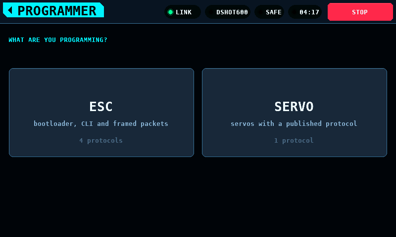
The ESC and SERVO classes are a model on the panel. No transport carries their protocols: CONNECT, READ and WRITE change the panel's own copy of a device and send nothing on a wire. The device named after CONNECT is the model's, not an answer from hardware, and a WRITE reaches no device. Every page of the two classes carries the MODELLED mark: on the class tile, on each protocol row and on the device line, where it takes the place of a connection's dot. The mark's dot is amber while a session is open and grey while none is; it never turns green. Under the parameters the page says that no device is reached. ESC STICK carries no mark: a stick run goes out through the arming policy and the output bank, as the MOTOR screen's commands do.
Every protocol row names its transport. There is no autodetection:
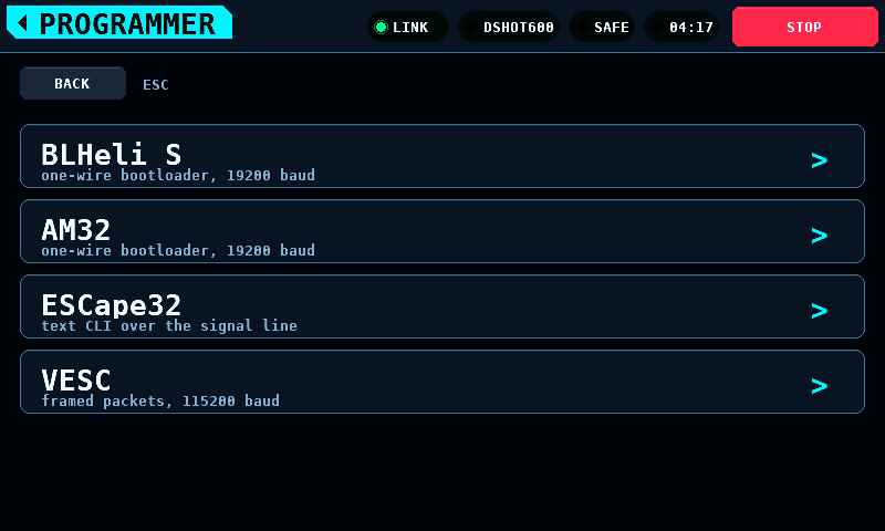
The ESC list has no entry for ESCs with BLHeli_32 firmware. The bench identifies and drives these ESCs and sends the DShot special commands, but cannot read their parameters: Parameters of ESCs with BLHeli_32 firmware.
Nothing is editable until CONNECT opens a modelled session:

With a session open, the parameters are shown in groups with the selected row's help under the list:
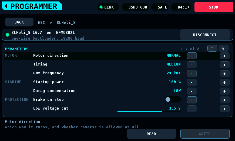
The settings of each firmware appear in its own units. The table for BLHeli_S firmware shows timing as named steps; the others show degrees of advance:

A changed value is not written to the model until WRITE is pressed. Staged changes carry a mark and their own colour, and the WRITE button shows how many are staged:

Steppers stop at the ends of a list; they do not wrap.
Every control on PROGRAMMER takes a tap. It acts when the finger lifts inside the control it pressed, no more than 8 px from the press in x and in y. A finger that comes down on a control and travels on presses nothing, and neither does one that crosses a control. One finger at a time presses a control. Three controls act on the press:
- HOLD TO RUN: its 2 s hold starts at the press.
- ABORT of a stick run, on the run's page and on a manual step's prompt. It stops a motor, so it does not wait for the lift, and it answers a second finger.
- The keys of the search keyboard, which follow their own press and lift.
Going back one level closes the session. Back climbs one level at a time; the band's home tag leaves the screen.
The list shows the makers first, alphabetical, each with how many of its models run:
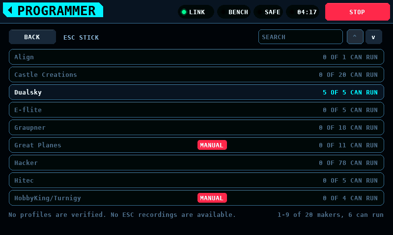
A maker opens its models, one row a model, by current, then voltage, then name, each with its family and what the profile is or why it does not run. A model opens its family's profile:

SEARCH filters the level showing. Its keyboard docks on the right, the rows
narrow beside it, and every key filters at once. A model is found when the
text appears in its maker and family read as one text, or in its maker and
its own name; a maker shows when any of its models is found. Case does not
matter, and * stands for any run of characters:

OK keeps the search on both levels, X clears it:

A profile's items start at KEEP. The steppers pick a value; RUN counts the values picked:

RUN opens a warning over the whole screen, NO PROPELLER, MOTOR SECURED?: a motor on the ESC must be mounted solid and carry no propeller, or a resistor load takes its place. The run starts after HOLD TO RUN is held for 2 s:
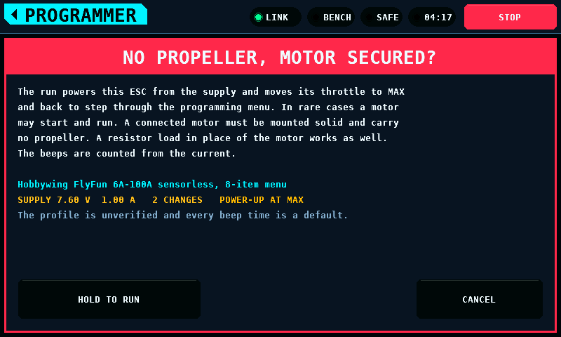
RUN opens nothing, and the line beside it names the reason, while no pin is bound as a throttle, while the output binding is not read, and while the supply is the panel's model; such a reason closes a warning that is open (Before a run).
A profile whose ESC needs a person at it -- a jumper fitted and pulled, a button pressed -- carries a red MANUAL tag in the list and MANUAL INTERVENTION REQUIRED in red on its page. The button shows the steps and when each is due; so does the first opening of the profile. The warning lists the steps due before the power-up, and the run stops for each later step with DONE and ABORT, waiting at most 60 s (Manual steps):
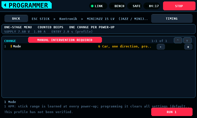

A Kontronik ESC that locks itself when its supply goes off before it has confirmed the stored mode holds the run powered after the store, the stick where it stored, until DONE:

While it runs, the page shows the phase, the beeps of the group under way and the last group. ABORT, STOP and leaving the screen end it with the throttle at MIN, the supply off and the bench SAFE. The stack light's green is on while a beep is detected, for at least 150 ms:
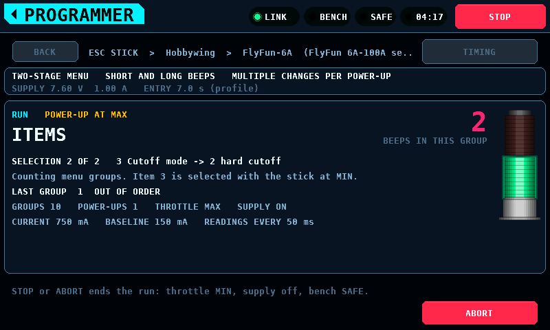
While the phase tap is enabled on SETUP the run's page adds a read-only readout under the current line: the tap's state, the pitch of its last 8 ms window, the counts of beeps the coprocessor lost and beeps the panel did not read, and the last four beeps with their number, length in ms and mean pitch in Hz. The run still counts its beeps from the supply current.
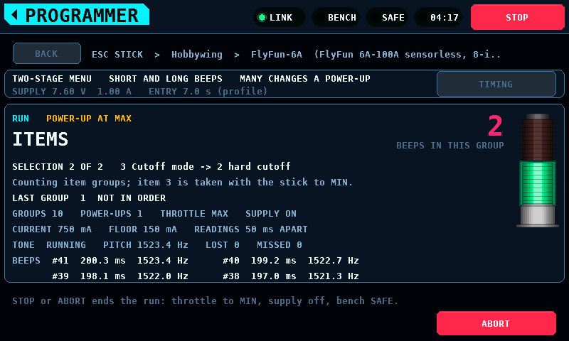
| State | Meaning |
|---|---|
RUNNING |
the capture runs |
OVERRUN |
it runs, and the capture ring or FIFO overran since the tap was enabled |
WAITING |
no link, or the TONE page has not answered in the last 500 ms, or its flags say the tap runs and its window number has not moved for 1.5 s, or the tap was switched off and the page still holds it on |
NO TONE PAGE |
the coprocessor speaks a protocol older than 4.8 |
PIN NOT FREE |
the coprocessor holds the tap off: its pin is bound elsewhere, or the coprocessor runs no capture since its boot (core 1 not started) and its saved set-up has the tap enabled; the second clears only with a restart of the coprocessor |
NOT RUNNING |
enabled, and the page holds the tap off or does not run it: the set-up was refused or is not written yet |
PITCH and LOST are the page's values from the last status read. They read
--, and OVERRUN is not shown, while no read younger than 500 ms gives the
state: in WAITING, in NO TONE PAGE, and in NOT RUNNING while the
set-up the page holds has the tap off. MISSED and the beeps are the panel's
own count and record and stay.
The result stays until OK. Its red light is on when the run ended because something was not as expected, a stop the bench raised itself included, and dark on DONE, a STOP pressed, ABORT and leaving the screen (the list):


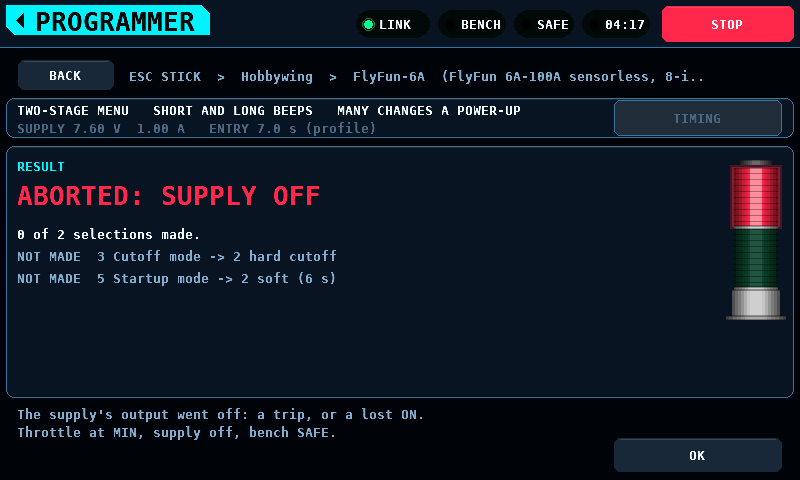
TIMING holds the beep timings and the supply settings. None of them is measured:


Cells are drawn as their departure from the pack's mean. The verdict follows the spread, the widest gap between any two cells: HEALTHY below 30 mV, WATCH from 30 mV, REPLACE from 60 mV. The scale follows the pack down to a floor of 12 mV and is printed beside the plot.
Measure under load. At rest a weak cell reads like the others.
No firmware feeds this screen: no cell monitor is read, so a bench shows NO PACK. The picture above is rendered from a model.

Browse the card, open a file, check what the import detected, then plot:

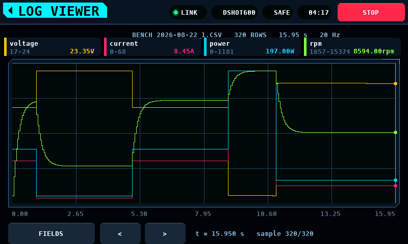
The CSV (comma-separated values) reader accepts decimal comma and decimal
point, a units row and ragged rows; the import view shows what it decided
before the file is plotted. Each numeric column shows its range, lowest to
highest: one decimal while both ends are below 1000, none from 1000 on
(11.9..12.6 V, 2392..14639 rpm). A range wider than the 17 glyphs of
its box drops the decimal, then the space before the unit
(-1000..-1000 rpm, -14639..-14639rpm); a wider one is cut at the box's
edge. A row ends at its line feed (LF, 0x0A).
Text after the last line feed is a row cut off by a power loss or a full
card: it can hold every field and a number cut short, 95 of 9554, so it
is left out of the rows, the figures and the plot. ROWS then shows in the
warning colour and the import view says LAST ROW CUT OFF - LEFT OUT. A
file from another program that ends without a line feed loses its last row
the same way. Spaces, tabs and carriage returns (CR) after the last line
feed are no row. Runs recorded by the bench are written as BENCH001.CSV to
BENCH999.CSV in the card's root directory. A run is one switching to
ARMED, or one switch-on of the SUPPLY output while the bench is SAFE. An
automatic servo test takes the next number too: its log is BENCHnnn.CSV,
which the list shows as a run, and its report BENCHnnn.TXT, which the list
does not show. A number carried by either file is taken, and DELETE on a run
removes its report too.
The list holds 48 entries and a card holds up to 999 runs. When there are more
than fit, the list keeps the newest runs and its tab reads 48 OF 137 FILES
instead of FILES, so a run that is missing from the list is a run the list
was too short for rather than a run that was never written. The number in the
name is what newest means: the panel has no clock that survives a power cycle,
so every file on the card is dated 1980-01-01. A run outranks a file the bench
did not write, so a card holding 48 or more runs lists no other file. Delete
old runs to get one back.
RESCAN, and every read of the card, selects the newest run and scrolls it into view, so OPEN opens the run just recorded. A card with no numbered run selects nothing.
In the plot, two fingers zoom: spreading them zooms in, pinching zooms out,
and moving both together pans. The view stays where the fingers leave it, and
a bar under the plot shows which part of the run is on screen. The narrowest
view is 8 samples, the widest the whole run. One finger and the < and >
buttons move the cursor as before; stepping the cursor past the edge of a
zoomed view carries the view with it. BACK returns to the import view.
The plot places the rows evenly by row number. The labels under it and the cursor's read-out are the file's time column, counted from the file's first row, and the header's duration is the last row's time less the first's. A gap in the rows is a jump in those times, not a wider stretch of plot. For a run with the bench in ARMED the time is wall time, so the duration is the run's; for a file written by firmware 0.15.0 or older it is shorter than the run (see Motor & ESC, the CSV file).
SETUP → APPLICATION → One finger pans, off by default, lets a single finger pan a zoomed view. While it is on and the view is zoomed in, a finger that moves more than 10 px from where it touched down drags the view sideways, and the sample under the finger stays under it. A touch that stays within 10 px selects a value as with the setting off, and a pan leaves the cursor where it was. A view that shows the whole run is not panned: one finger moves the cursor. A second finger on the plot starts a zoom, as before.
A button or a row on LOGS takes a tap. It acts when the finger that pressed it lifts inside it, having been no more than 8 px from the press in x and in y. A vertical drag of more than 8 px on the file list or on the column list scrolls it and selects nothing. On those two views one finger at a time presses; a second finger does nothing.
DELETE removes the selected file from the card. It asks first: a second panel names the file and its size, and only its own DELETE, pressed and released on that button, removes the file. CANCEL, or leaving the screen, closes the question without deleting. The run the logger has open is refused. A file that was open in the import view or the plot is dropped from both when it is deleted. The logger numbers each run above the highest run it found on the card. It reads the card at the first run after boot and after a run that could not be opened, and counts on from there otherwise. A deleted number is used again only if it was above every run left on the card at that read.
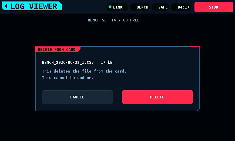
A run is committed to the card every 20 rows or 1000 ms of run, whichever comes first. Power lost mid-run costs the rows the commit has not finished with and the rows still in the queue between the control task and the card's own task: under 1.0 s of run while the card keeps up, and 84 rows, 4.20 s at the panel's 20 Hz sample rate, if the card has stalled and the queue is full. The rest of the file is readable either way; a row the cut stopped part way through has no line feed and is left out on reading (see Logs). The card is written by a task of its own: an SD (Secure Digital) card is allowed 250 ms to finish a write, and the task that beats the safety line has a ceiling of 150 ms.
Eight messages say what a card did to a run. Each appears on the band:
| Message | What happened |
|---|---|
no card -- this run is not recorded |
nothing is mounted, so the run was never opened |
card unreadable -- run not recorded |
the card would not list, so a run number could not be chosen |
card full or unwritable -- run not recorded |
no run number could be created |
the card did not keep up -- run not recorded |
every row was dropped, so there is no file for this run at all |
the card fell behind -- the log has gaps |
some rows were dropped; the file's time column shows where |
the card stopped taking rows -- run not recorded past here |
a write failed mid-run; every later row is rejected |
the card stopped taking rows -- the log is short |
the same failure, said again when the run closes |
the card failed on the last write -- the log is short |
the close failed, so the rows since the last commit are not in the file |
The first four mean there is no file to look for. The last four mean there is one and it stops early.
A run being written is not offered in LOGS. A file's length lives in its directory entry and is written when the file is closed, so a run still open would list at its last committed length and read as a finished one.
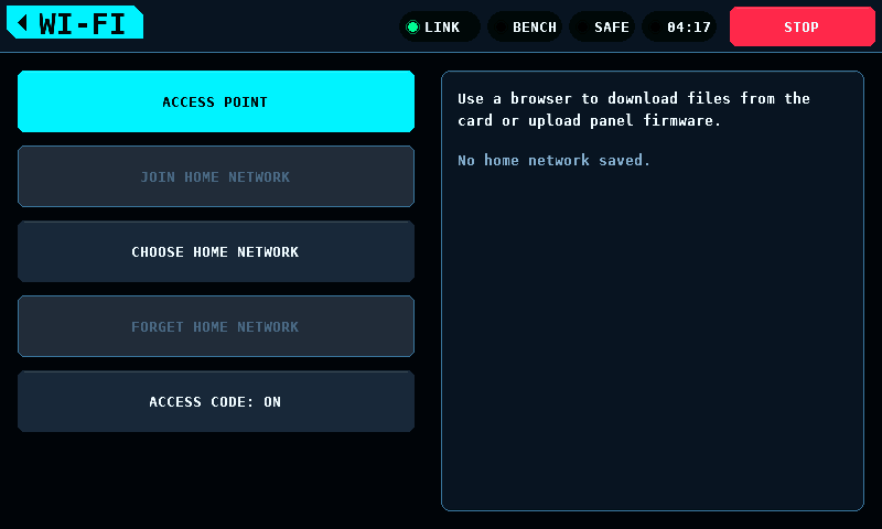
FILES & UPDATE runs the panel's Wi-Fi for two jobs in a browser: every file on the card to download, and a panel firmware image to upload. It opens from LOGS, with WI-FI in the bottom row beside RESCAN. The radio runs only while this screen is open, and for the release check and the download of Updates. It is off at every start of the panel, and it goes off when the screen is left, before an install writes the flash, and after 10 min without a request.
The radio starts only with the bench SAFE, the supply output off and no log run open. Otherwise the buttons that start it are grey and the card says what is missing:

It goes off by itself on a switch to ARMED, on STOP, on the supply output
coming on, on a log run opening, after 10 min without a request and after 16
wrong access codes. The card then says which, in one line:
Wi-Fi went off: ARMED., Wi-Fi went off: STOP.,
Wi-Fi went off: supply output on., Wi-Fi went off: a log run opened.,
Wi-Fi went off: 10 min without a request.,
Wi-Fi went off: 16 wrong access codes., or Wi-Fi did not start. A STOP
or a switch to ARMED also drops an uploaded image that waits on the panel.
While the radio is up, the link to the coprocessor and the heartbeat run as
on every other screen.
When Wi-Fi could not be set up at start (no memory for its lock or its
buffers), every button is grey and the card says Wi-Fi is unavailable: its set-up failed at start. A restart tries again. The rest of the panel runs
as without Wi-Fi.
ACCESS POINT starts the panel's own network. The screen shows what a phone or a computer needs:

| Band and channel | 2.4 GHz, channel 6 (WIFI_ACCESS_AP_CHANNEL) |
| Security | WPA2 (Wi-Fi Protected Access 2) personal |
| Network name |
rcbench- and 4 hex digits of the panel's MAC (media access control) address, rcbench-3F7A
|
| Password | 8 characters, made new at every start, from abcdefghjkmnpqrstuvwxyz23456789 (no 0, 1, i, l or o) |
| Clients | 1 at a time |
| Address | http://192.168.4.1/ |
| Range | not measured |
- LOGS → WI-FI → ACCESS POINT.
- On the phone or the computer, join the network the screen names, with the password it shows.
- Open
http://192.168.4.1/and enter the access code the screen shows.
The panel can join a network that is already there instead: WPA2 or WPA3 (Wi-Fi Protected Access 3) personal. Enterprise networks and open networks are not offered.
CHOOSE HOME NETWORK scans for 10 s at most, then lists up to 16 networks, strongest first, with their signal in dBm. A network without a name, an open one and an enterprise one are left off the list.


A tap on a network opens the keyboard for its password. HIDDEN NETWORK opens it for the name of a network that does not announce itself, and then for the password. SCAN AGAIN scans again; CANCEL goes back.


The keyboard has three layers of the same grid: lower case, ABC for upper
case, #+= for the 32 printable marks of ASCII (American Standard Code for
Information Interchange). Each of the 95 printable ASCII characters is on
one layer once; SPACE is the wide key. A name takes 1 to 32 bytes. A
password takes 8 to 63 characters, the WPA2 and WPA3 personal range: the
64th is refused, and OK under 8 says so.


The password shows as dots until SHOW; HIDE hides it again. OK keeps the network: its name and its password go to NVS (non-volatile storage), and the screen then offers JOIN HOME NETWORK.


Joined, the screen shows the network, the panel's address and its name,
http://rcbench-3F7A.local/, with the same 4 hex digits as the access
point's name. The name answers through mDNS (multicast domain name system)
on computers that resolve .local names; which phones do is not measured.
The address works on every one. A name responder that fails to start (no
task, no socket, no multicast group) is tried again 3 times, 5 s apart
(WA_MDNS_RETRIES, WA_MDNS_RETRY_MS); after that the name stays silent
until the next join, and the address still works.
A join that fails says why, and offers ACCESS POINT, which works without the home network:
| Line on the card | Condition |
|---|---|
Join failed: password refused. |
3 auth-class drops in a row within 20 s (WA_AUTH_TRIES): the key refused, a MIC (message integrity code) failure, or the key handshake out of time; or no association within 20 s (WA_JOIN_MS) with an auth-class drop as the last drop |
Join failed: network not found. |
no association within 20 s (WA_JOIN_MS), and the last drop of another kind, or none |
Join failed: no address in 15 s. |
associated, and no address from DHCP (dynamic host configuration protocol) within 15 s (WA_ADDRESS_MS) |
The home network went away. |
joined, then the network dropped the panel |
A drop while joining connects again. One auth-class drop does not end the
join: ESP-IDF reports a wrong password and a key handshake answered late
with the same reasons, 15 and 204, and a correct password is answered late
when the panel or the router is busy. Any other drop sets the count back
to 0. Each drop goes to the serial log as one line with its reason number
(ESP-IDF's wifi_err_reason_t).
FORGET HOME NETWORK erases the name and the password from NVS and sets the access code back to on.
A change of what is kept (a network, FORGET, the access code switch) takes
effect at once and reaches NVS on the next frame that may write flash. A
write that fails is tried again 3 times, 10 s apart (WA_PENDING_RETRIES,
WA_PENDING_RETRY_MS), and the card says Not saved: the flash write failed. Another change tries again. until one succeeds. The change holds
until the panel restarts either way; only a write that succeeded outlasts
the restart.
Current limitations:
- NVS is not encrypted. The home network's password is kept in plain form in the panel's flash, where anyone who reads the flash over USB (Universal Serial Bus) reads it.
- The page is plain HTTP (hypertext transfer protocol). On a home network the access code and every file cross the network unencrypted. The screen says so while joined.
- An uploaded image is checked against its own SHA-256, not against a
signature. Any image built as
rcbench-panelfor the ESP32-S3 installs after the 2 s hold, and on a home network a device between the browser and the panel can replace the image on its way. The coprocessor image a panel image carries comes with it and is offered to the coprocessor at the next link-up. - The panel joins only while this screen is open. A panel that stays joined whenever the bench is SAFE is not built.
The page asks for an 8-character code before it lists a file or takes an upload. The screen shows it, and it is made new at every start of the radio, so a code from an earlier session opens nothing. The browser keeps it for the session. 16 wrong codes switch the radio off.
ACCESS CODE switches it, for both ways in. It is on by default, after
FORGET HOME NETWORK and on a panel with nothing kept. The switch is kept in
NVS. Off, the page lists, sends files and takes an upload without a code,
and the screen says Access code off: the page is open to every device on the network. An upload still installs only after the 2 s hold on the
panel.
One HTML (hypertext markup language) page, with no script or style from elsewhere, so it works on a phone with no other connection. It follows the panel's language. It has two parts.
Panel firmware. The version installed, a file picker, Upload with a
progress bar, and the panel's answer as a line of text. The file is the
release asset rcbench-panel-vX.Y.Z.bin. A file larger than the panel's
slot, 4,063,232 bytes, is refused before a byte is sent. The panel checks
the whole image before it asks anything: the ESP image header for the
ESP32-S3, the application's project name rcbench-panel, a version of the
form MAJOR.MINOR.PATCH and the appended SHA-256 (secure hash algorithm, 256
bits). A second upload while one waits is refused until CANCEL on the panel.
The screen shows the bytes received while an upload runs.
Files on the card. Every file, folder by folder, with its name, its size in bytes and its modification time as the card has it. Each name downloads that file. The page reads the card only: nothing on it is deleted, renamed or written. A name over 255 characters, a path over 384 bytes and a folder deeper than 16 are left out, and the page says how many. With no card, or a card that cannot be read, the page says so and the upload still works.
Download all as one ZIP file sends the whole card as one ZIP file. The page gives the number of files, their bytes and the ZIP file's bytes before the click. The files are stored as they are, not compressed, with their folder paths from the card's root, names in UTF-8 and the card's times. A file over 4 GiB − 1 B, an archive over 4 GiB − 1 B and more than 65,535 entries use ZIP64. Nothing is held in memory or written to the card to make it: it is sent as it is read.
The transfer rate is not measured. A download of S bytes at a rate of R bytes per second takes S / R seconds: at 1,000,000 B/s, a 50,000,000-byte card takes 50 s. A card pulled during a download ends the download short; the browser reports it as failed, and the panel runs on.
An image the page received waits on the panel as a question with both versions:

An older version is allowed and the question says it is older. A board drawing being fetched or kept makes the install wait:

The same version from another build is offered as a reinstall. The build that runs already is not offered:


INSTALL is a 2 s hold (HOLD 2 s: INSTALL). The browser cannot start it.
It needs the bench SAFE, the supply output off, no log run open, no board
drawing being fetched or kept and no update of the coprocessor running
(Install waits: the coprocessor's update runs.). CANCEL drops the image.
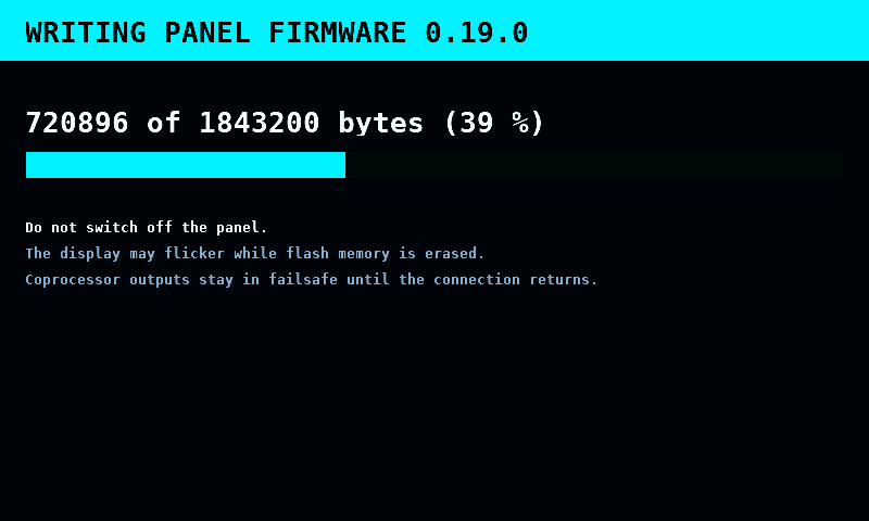
The hold switches the radio off first. Then the control task stops its polls and withholds the heartbeat on purpose, so the coprocessor holds its outputs in failsafe as it does at any restart of the panel. PANEL UPDATE takes the whole screen, with no band and no STOP: nothing can be switched to ARMED behind it. It writes the slot that is not running in pieces of 64 KiB and shows the bytes and the percentage. The picture can be disturbed while the flash is erased, and is in place again from the first whole frame after each erase. Then the slot is read back and checked, it becomes the one that starts, and the panel restarts.
The splash shows the new version, and the band says
panel firmware 0.19.0 installed. A write that fails changes nothing that
starts: the running build stays, and CLOSE goes back to LOGS, or after a
download from GitHub to where the download started.
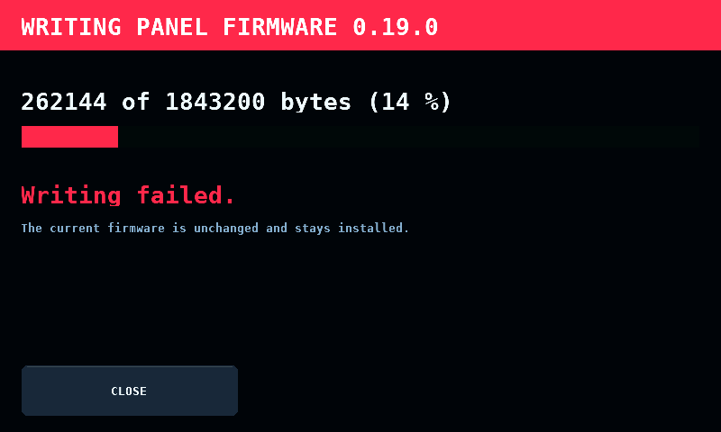
A new build's first start is a trial. The build is kept once the display and
touch are up. A start that does not get there, by a fault, a restart or a
missing touch controller, goes back to the build before it, which says
panel firmware 0.19.0 did not start -- 0.18.0 runs again on the band.
A failed start is never kept: when marking it invalid fails, the panel
restarts with the trial unconfirmed, and the bootloader goes back all the
same. When keeping a good start fails (otadata not written), the band says
panel firmware 0.19.0 not kept -- the next start goes back; the build
runs until then.
Current limitations:
- A power cut during the trial start loses that line; the panel still goes back to the build before.
- How long the erase and the write take is not measured, and neither is what the glass shows during an erase.
Before the first update over Wi-Fi, the panel needs one flash over USB to reach the layout with two application slots: First run, §1.
The SETUP tile of the menu opens a page of tiles, 3 by 3, in the menu's style. Each tile is 256 x 108 px, its icon centred over its name.
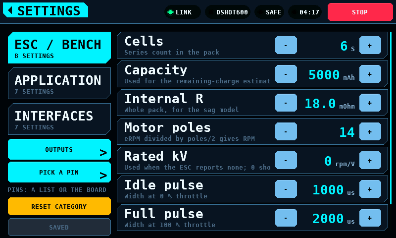
- Three categories: ESC / BENCH, APPLICATION and INTERFACES. Each tile names its number of settings. A tap opens the category's list.
- Three screens of their own: OUTPUTS (Outputs), PICK A PIN (Pick a pin) and UPDATES (Updates).
- Three slots are free. A tenth entry has no slot: the page holds 9, and the build fails at the tenth.
- SAVE, bottom right, is the same button the lists show (Keeping the values). A change left unsaved in any category shows here too:

The same page in the light theme:

A category's list spans the panel's width, 776 px, and shows 348 px of it, 6 rows, over a strip of three columns: the category's name, RESET CATEGORY and SAVE. The strip ends at panel y 442, 4 px above the alert band (The alert band), so an alert never covers a key, a row, RESET CATEGORY or SAVE, on the tiles or on a list.
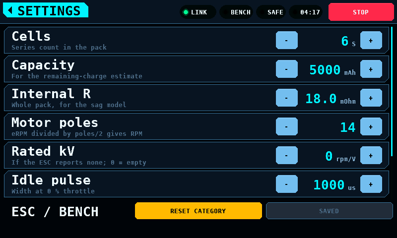
The home tag climbs one level at a time:
| From | The home tag leads to |
|---|---|
| a category's list | the tiles; the list keeps its position |
| the tiles | the menu; with a value unsaved, the warning first (Leaving with values unsaved) |
| OUTPUTS, PICK A PIN, UPDATES | the tiles |
The menu's SETUP tile always opens the tiles. Leaving SETUP writes nothing, from the tiles or from a list.
APPLICATION's Language switches the whole interface between English and German on the next frame, with no restart. What follows it, what stays English and why: Interface language. One finger pans, in the same category, sets whether one finger pans the zoomed log plot; it is off by default and is described under the log viewer.
Nine settings are stored and shown, and no part of the firmware reads them: Backlight, Units and Dim after under APPLICATION; Cells, Capacity and Internal R; Vibration, Optical tacho and Tacho pin. Ramp limit is read only as the slew of the modelled bench.
A row's - and + keys (< and > on a switch or a choice) change its
value by one step. A changed value is in force at once; SAVE decides whether
it survives a restart (Keeping the values).
- Tap. A key steps once when the finger lifts. The lift counts when the finger is the one that pressed the key, is inside the key, and is no more than 8 px from the press in x and in y. The key is drawn pressed from the press on.
- Hold. A key held steps for the first time 0.45 s after the press, then 8 times a second, and 30 times a second from 2.25 s after the press. Held for 1.00 s it has stepped 5 times, for 3.00 s 38 times. The lift after a hold adds no step. The hold ends when the finger is more than 8 px from the press or outside the key.
- Scroll. A vertical drag of more than 8 px that starts anywhere on the list scrolls it, the key columns included. A scroll changes no value. The bar at the list's right edge shows the position and takes no touch.
- A key is its column, 44 px wide, over the 54 px of its row. The 4 px between two rows belong to no key.
- One finger at a time. While one presses or scrolls, a second finger does nothing on this screen.
Two limits:
- A finger that rests on a key for 0.45 s or longer and then scrolls has stepped the key: that is a hold.
- A contact the touch controller leaves out of one report arrives as a lift and a new press. If the new press is on a key and lifts there without moving, it is a tap. How often the GT911 drops a moving contact from a report is not measured.
An AS5600 magnetic angle sensor on the panel's I2C terminal (I2C: Inter-Integrated Circuit) turns the slider of the bench screen on top: the throttle on MOTOR & ESC, the horn on SERVO. Wiring: Building. Other screens ignore it.
| Setting | Range | Default |
|---|---|---|
| Rotary knob | OFF, ON | OFF |
| Knob scale | 90 to 720 deg in steps of 10 | 270 deg |
Knob scale is the knob angle that moves the slider across its whole span. At 270 deg a quarter turn moves the throttle 33.3 points, and the horn across a third of its travel from -travel to +travel.
- The knob moves a value by how far it turns, never to where it points. A turn adds to the throttle or the horn's angle and stops at 0 and 100 % or at the travel limit. Turning past an end and back moves the value from the end.
- It never switches to ARMED. ARM is the same hold on the same button.
- The first reading after power-up and the first one after the sensor stopped answering set a reference and move nothing, so a knob that comes back turned does not jump the slider.
- The sensor is read every 10 ms, and every 100 ms while it does not answer. A reading with no magnet detected, a magnet too weak or too strong, or a magnitude of 0 counts as no answer. A step of more than 90 deg between two readings counts as a glitch and is dropped.
- A finger on the throttle track or on the SERVO dial owns the value while it is down, and for the whole frame in which it touched the control, also when it lifts in that frame. On SERVO the knob does not take the horn from a running or paused sweep, a test run, or the open settings panel.
- A frame that lost touch events drops the knob's motion with its gestures, and so does a frame in which the router navigated at all, also away from the screen and back to it. The knob's command goes out with the next frame; if that frame finds lost touch events first, the command is withdrawn and the slider returns to its value from before the knob.
- The knob replaces only a throttle or a horn position. While another command waits for the frame (a switch to ARMED that has just completed, a switch to SAFE, a peak reset, a release), the knob's motion in that frame is dropped, not held.
- On SERVO a turn while the bench is SAFE moves nothing and is not kept. The switch to ARMED sets the horn to the rest, and the next turn counts from there. A turn posted and not yet sent when the bench switches to SAFE or stops is withdrawn. On MOTOR & ESC a turn while the bench is SAFE moves nothing and is not kept either; the switch to SAFE returns the slider to 0 %, and the next turn after a switch to ARMED counts from there.
- Known limitation: On the Waveshare ESP32-S3 Touch LCD 7 panel the board's CH422G I/O expander answers at I2C addresses 0x20 to 0x27 and 0x30 to 0x3F, which includes the AS5600's fixed address 0x36, so an AS5600 knob cannot be read on that bus. The Rotary knob setting is OFF by default.
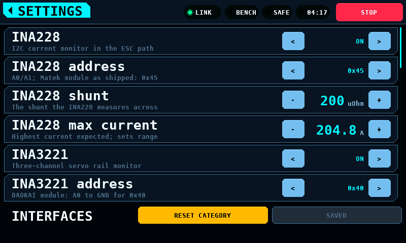
The coprocessor reads two I2C (Inter-Integrated Circuit) current monitors on one bus on two of its pins: a TI INA228 in the ESC's power path and a TI INA3221 on the servo rail. Their rows are at the top of INTERFACES:
| Setting | Range | Default | |
|---|---|---|---|
| INA228 | ON, OFF | OFF | the monitor in the ESC's power path |
| INA228 address | 0x40 to 0x4F | 0x45 | the MATEK I2C-INA-BM as shipped; its solder bridges give 0x44 or 0x41 |
| INA228 shunt | 50 to 20000 µΩ, 1 µΩ steps | 200 | the MATEK's |
| INA228 max current | 1.0 to 300.0 A, 0.1 A steps | 204.8 | the current the range is set for: it chooses the ADC (analog-to-digital converter) range and nothing else. 300 A is the bench's design maximum; the coprocessor refuses more. Its refusal of a range past 2000 A full scale stays, and 300 A on the smallest shunt, 50 µΩ, does not reach it |
| INA3221 | ON, OFF | OFF | the servo rail's three channels |
| INA3221 address | 0x40 to 0x43 | 0x40 | the DAOKAI module with its A0 solder bridge closed to GND. As shipped all four A0 bridges are open and the address floats between 0x40 and 0x41 |
| INA3221 shunt | 5.0 to 1000.0 mΩ, 0.1 mΩ steps | 100.0 | one a channel; the DAOKAI's R100 reads to 1.64 A |
| INA3221 channels | CH1, CH1+2+3 | CH1 | CH1 is the servo test's; CH2 and CH3 a synchronised pair's |
| Sensor SDA | −1, 0, 4, 6, 14, 16, 18, 20, 26 | 16 | coprocessor GPIO (general-purpose input/output). - and + step from one of these values to the next and stop at −1 and at 26. −1: the pins are not set, and no part is enabled on the page |
| Sensor SCL | SDA + 1, or −1 | 17 | the GPIO after Sensor SDA, and −1 with it. The row shows the value and has no keys |

SDA and SCL are one I2C block's pair: SDA's GPIO number mod 4 is 0 or 2, and
SCL is the GPIO after it. Sensor SDA takes only the pins of such a pair that
the RP2350-CAN brings out and does not reserve: GP2 is left out because GP3
is the heartbeat, GP8 to GP12 are the CAN controller's, and GP22, GP24 and
GP28 because the module does not bring out GP23, GP25 and GP29. The rule is
the one the coprocessor's SENSE page judges a write by
(link_sn_pins_pair(), settings_sense_sda_valid()). A pin an output, the
PD mini or the phase tap holds is offered all the same, and the coprocessor
refuses it. With Sensor SDA at −1 the panel writes ENABLE 0, SDA 0 and SCL 0
to the page.
Stored settings: the sns_scl key is not read. Sensor SCL is derived from
the stored Sensor SDA, and the key is saved with the derived value. A stored
Sensor SDA outside the values above loads as 16, with no alert and without
marking the settings as changed.
The bus runs at 400 kHz, which is not a setting: the coprocessor takes no other clock. A reading at the top of the INA3221's range, 163.8 mV across the shunt, is shown as clipped and never as a value.
The panel writes the set-up to the coprocessor's SENSE page (protocol 4.7) 500 ms after the last edit, only while the bench is SAFE, and only what differs from what the page holds: the coprocessor refuses a change while it drives, and keeps each change in flash. It reads the page at every link-up first, so a set-up the coprocessor already keeps is not written again. When a monitor's own values change while both are enabled, both are switched off on the page first and on again after, so no step on the way puts the two parts on one address. A coprocessor older than 4.7 is sent nothing. After a write is taken the panel reads the coprocessor's identity again: capability bits 3 and 4 follow the set-up, and with the INA228 enabled the MOTOR & ESC tile loses its MODELLED mark.
While a monitor is enabled, the panel reads SENSE's 14 read-only registers every 50 ms; while the INA3221 is, SERVO_SENSE's channel windows every 50 ms, each 50 ms window once. With a coprocessor of protocol 4.11 and CH1 among the INA3221's channels it also reads SERVO_WIN every 50 ms, which holds CH1's last four windows, and SENSE to register 31 (Link).
The servo rail has one meter at a time: the INA3221's CH1 while it is on with CH1, the coprocessor speaks protocol 4.11, the coprocessor holds the set-up, the part answers as an INA3221 on a bus that is not stuck, a window with current samples closed in the last 200 ms, its reset count stands, and all of that has held for 1000 ms; the PD mini otherwise. The SERVO screen's CURRENT row, line and plot show the meter's reading (Servo); the servo test reads the PD mini whichever it is.
The band says what they show, each once and one at a time: the most pressing first, and the next no sooner than 5 s later, so two at once are both said. In order:
| Message | When |
|---|---|
coprocessor has no SENSE page -- current monitors not read |
a monitor is enabled and the coprocessor speaks a protocol older than 4.7; said at the link-up, and when a monitor is enabled while it answers |
sensor SDA or SCL not set -- see SETUP INTERFACES |
a monitor is enabled with a pin at −1; neither is enabled on the page |
INA228 and INA3221 both at 0x40 -- see SETUP INTERFACES |
both enabled on one address; neither is enabled on the page |
sensor pins GP16/GP17 refused -- see SETUP INTERFACES |
the coprocessor refused the pins: bound to an output, held by the PD mini or the phase tap, or reserved; both monitors stay off. Shown for 30 s or until tapped, once per edit |
INA228 shunt or max current refused -- see SETUP INTERFACES |
the shunt's voltage at the max current passes 163.84 mV, or the range it gives passes 2000 A; the INA228 stays off |
INA3221 set-up refused -- see SETUP INTERFACES |
the INA3221 stays off |
sensor bus stuck: SDA held low -- clocking it free |
the coprocessor found SDA held low and clocks it free |
INA228 not answering at 0x45 |
enabled, and not answering 2.5 s after its set-up was taken, or no longer answering after it did. -- 0x44 answers is added when the coprocessor's address scan found something where the part could be |
0x40 answers 1408h, not an INA3221 -- not used |
something answers at the part's address with another identity |
INA228 current at the end of its range -- current is a bound |
the INA228 read the end of its range in the last 50 ms window or since the switch to ARMED |
INA3221 CH1 clipped at 1.64 A -- current is a bound |
a channel the INA3221 reads hit the top of its range; the current is its full scale |
coprocessor store off -- set-ups last until it restarts |
STATUS fault bit 6: the coprocessor saves nothing this boot, so the set-up, the bindings and the supply's wiring are lost at its restart; said once per link-up |
coprocessor older than 4.11 -- servo current read from PD mini |
the INA3221 is on with CH1 and the coprocessor speaks protocol 4.7 to 4.10: it has no window ring, and the PD mini is the servo rail's meter. Said at the link-up, and when the INA3221 is switched on while it answers |
INA3221 reset itself -- check its supply |
the coprocessor found the INA3221 on its power-on set-up and set it up again 1000 ms later; said once per reset. The windows of those 1000 ms hold no samples |
A refused set-up is not written again until it changes on SETUP. Pins that are one I2C block's pair, refused because an output, the PD mini or the board holds one, are offered again every 5 s without another alert, so freeing the pin on OUTPUTS or SUPPLY lets the bus open. A monitor that stops answering does not switch the bench to SAFE: nothing trips on the monitors' readings.
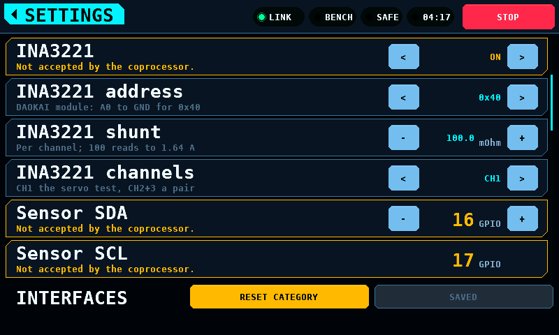
A row whose value is not the one the coprocessor's page holds is marked: its
edge and its value are drawn in the warning colour, and its help line reads
Not taken by the coprocessor. The panel compares the set-up it asks for
with the one the page last acknowledged or read back (sense_link_unheld(),
tone_link_unheld()). The mark covers the current monitors' rows, Sensor
SDA and Sensor SCL (one mark, the pins are one frame), AS5600, and the phase
tap's rows in two groups: Phase tap, Tap pin and the two tones, and Tap
pitch split, Tap gap and Tap min periods.
| The mark shows | Until |
|---|---|
| from an edit | the write is acknowledged: 500 ms after the last edit, and for the current monitors only once the bench is SAFE |
| on a value the coprocessor refused | the value is changed to one it takes; for pins held elsewhere, until the 5 s retry is taken |
| on INA228, INA3221 or AS5600 at ON while the page has the part off | the cause is gone: a refused frame, Sensor SDA at −1, both monitors on one address, a coprocessor older than the part |
| after a coprocessor restart or a link-up, on what its page reads differently | the panel has written it |
No row is marked while no coprocessor answers, or before the page has been read after a link-up: there is nothing to compare with. AS5600 centre is the panel's own and is never marked. The alert on the band is separate and stays as described above.
An ams OSRAM AS5600 magnetic angle sensor on the servo's output shaft, on the sensor bus beside the monitors, at its fixed address 0x36 (protocol 4.9):
| Setting | Range | Default | |
|---|---|---|---|
| AS5600 | ON, OFF | OFF | the output encoder; it takes the sensor bus's SDA and SCL above, and needs both pins set |
| AS5600 centre | 0 to 4095, 1 count steps | 0 | the sensor's 12-bit count with the servo at its neutral; 4096 counts a turn, 0.0879 degrees a count. The SERVO screen's ENC CENTRE sets it from the live reading |
The panel writes the enable bit with the rest of the bus frame, 500 ms after the last edit and only while the bench is SAFE, to a coprocessor that names protocol 4.9; an older one is sent nothing. While the encoder is enabled it reads SENSE's registers 12 to 31 every 40 ms. The band says, each once and one at a time like the monitors':
| Message | When |
|---|---|
coprocessor older than 4.9 -- AS5600 not read |
the encoder is enabled and the coprocessor speaks a protocol older than 4.9; said at the link-up, and when the encoder is enabled while it answers |
AS5600 not answering at 0x36 |
enabled, and not answering 2.5 s after its set-up was taken, or no longer answering after it did; also when something at 0x36 gives a STATUS no AS5600 gives, ML and MH both set |
AS5600 sees no magnet -- check the magnet on the horn shaft |
it answers, an angle has been read, and STATUS MD (magnet detected) is clear. The count is no angle: MEASURED shows ---, ENC CENTRE sets nothing, and a run logs and judges no angle |
AS5600 magnet too weak -- move it closer |
STATUS MD and ML are set. The angle is used; the sensor's datasheet specifies its noise for 30 to 90 mT only |
AS5600 magnet too strong -- move it away |
STATUS MD and MH are set. The angle is used, as with ML |
A magnet message is said once until the field reads right again, and again when a magnet that read weak or strong goes missing or a missing one comes back weak or strong: the angle stops with the first and returns with the second. The sensor's DIR pin sets the direction its count rises in; the panel takes the count to rise with the servo's pulse width.
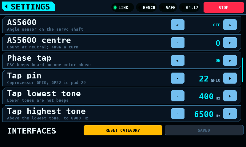
The phase tap hears an ESC's beeps on one motor phase. One coprocessor GPIO reads the phase through a series resistor and a zener clamp; the coprocessor times the pin's edges and reports each beep's length and pitch. The wiring is not in the build guide. The tap is an input: it drives nothing, and the coprocessor takes a change ARMED or not. Its rows follow the bus's pins:
| Setting | Range | Default | |
|---|---|---|---|
| Phase tap | ON, OFF | OFF | the capture runs on the coprocessor |
| Tap pin | 0 to 47 | 22 | coprocessor GPIO; GP22 is pad 29. Refused: an ADC (analog-to-digital converter) pin, GP26 to GP29 on the RP2350A and GP40 to GP47 on the RP2354B; a pin bound to an output; a pin the SENSE or SUPPLY page holds |
| Tap lowest tone | 50 to 2000 Hz, 10 Hz steps | 400 | a tone below it is not a beep |
| Tap highest tone | 100 to 6900 Hz, 50 Hz steps | 6500 | above the lowest tone |
| Tap pitch split | 0 to 50 %, 1 % steps | 8 | a pitch change this large starts a new beep with no silence between; 0 splits on silence only |
| Tap gap | 1 to 100 ms | 3 | the silence that ends a beep; at least one period of the lowest tone, so 20 ms at 50 Hz |
| Tap min periods | 1 to 64 | 3 | the tone periods that make a beep |
The panel writes the set-up to the coprocessor's TONE page (protocol 4.8)
500 ms after the last edit, and only what differs from what the page holds:
the coprocessor keeps each change in flash. It reads the page at every
link-up first. The set-up goes in two frames, the pin and the tone range,
then the split, the gap and the periods. When both change, the one that
leaves the page a valid set-up goes first: a lower tone with a gap shorter
than its period is refused, so the gap is written before the tone goes down
and after it goes up. Switching the tap off writes the first frame with
the values the page holds and the tap disabled, whatever range is asked, so
a range the page would refuse cannot keep the tap running; the range
follows in a frame of its own. Until the page holds the tap off the screen
shows WAITING, not off. A set-up kept in flash that met a busy pin at the
coprocessor's boot is written again every 5 s, without another message,
while the page reports the pin refused. A change of ENABLE or of the pin
empties the coprocessor's ring and the panel takes its place at the newest
beep number, so none is read twice and none counted as missed; a change
of the range or of the other values leaves the ring and the numbering
alone. A coprocessor older than 4.8 is sent nothing.
While the page holds the tap on, the panel reads its 16 read-only registers
every 50 ms: the flags, the last 8 ms window's pitch, the number of the
newest beep and the counts of beeps lost and lows ignored. A read whose
flags say the tap runs speaks for it while its window number moves: the
coprocessor closes a window every 8 ms, so a number that has stood for
1.5 s (TONE_LINK_WINDOW_STALE_MS) is a capture that stopped while the
page still answers, and the screen shows WAITING as for a read older
than 500 ms. It takes the
beeps one by one by number. The coprocessor keeps the last 64 beeps,
numbered 1 to 65535 and then 1 again, and a read does not remove one, so a
reply lost on the link loses no beep. A beep that left the ring before it
was read, or that the ring moved past while the panel was more than 64
behind, is counted as missed. The last 8 beeps are kept for the screen; the
run page of ESC STICK shows 4 of them (Programmer).
The band says what the tap reports, each once and one at a time, as for the current monitors:
| Message | When |
|---|---|
coprocessor has no tone page -- phase tap not read |
the tap is enabled and the coprocessor speaks a protocol older than 4.8; said at the link-up, and when the tap is enabled while it answers |
phase tap on GP22, 400 to 6500 Hz refused -- see SETUP INTERFACES |
the coprocessor refused the first frame: the pin is not allowed, the tone range is not one it takes (the highest tone not above the lowest, or the gap shorter than the lowest tone's period), or it runs no capture since its boot (core 1 not started). A pin that an output, the sensor bus, the PD mini or a programming port holds is refused as busy (BUSY, protocol 4.17): offered again every 5 s without another message, so freeing the pin lets the tap start. Any other refusal is written again only after the next change on SETUP INTERFACES or link-up. From a 4.16 or older coprocessor, which says BAD_VALUE for both, the frame is offered again every 5 s when its tone range and gap are valid (Link) |
phase tap split, gap or periods refused -- see SETUP INTERFACES |
the coprocessor refused the second frame; not written again until a value changes |
phase tap pin GP22 not free -- tap not running |
the coprocessor reports the pin refused, for one of two causes. A set-up it kept in flash met a binding at its boot: the first frame is offered again every 5 s without another message, so freeing the pin lets the tap start. The coprocessor runs no capture since its boot (core 1 not started, protocol 4.17): no pin is bound and freeing one changes nothing. The next offer of the first frame is refused with BAD_VALUE without another message, and the frame is not offered again until the next change on SETUP INTERFACES or link-up; only a restart of the coprocessor lets the tap run. The band says phase tap on GP22, 400 to 6500 Hz refused -- see SETUP INTERFACES only for a set-up other than the one the coprocessor kept, written at link-up before the first status read or less than 5 s after the pin was first reported not free or last offered; a change made later goes out as a quiet offer |
phase tap capture overrun -- beeps cut |
the coprocessor's capture ring or FIFO (first in, first out buffer) overran since the tap was enabled; the beep under way was cut |
A changed value takes effect at once and is not written to flash until SAVE is pressed. SAVE, beside RESET CATEGORY on a list and alone on the tiles, says which of four states the values are in. The values are one set: the state is the same on the tiles and on every list.
| Label | Meaning |
|---|---|
SAVED |
Nothing is unwritten. The button is inert. |
SAVE |
Something is unwritten. Pressing it asks for a write. |
WHEN IDLE |
A write has been asked for and is waiting for a moment to happen in. |
NOT SAVED |
The store refused the write. What reached the medium is not known from the screen: a refusal on one key leaves the keys written before it committed, so the next boot can load a mix of the new values and the old. Pressing it tries again. |

The press asks; it does not write. Writing settings commits a page of NVS
(non-volatile storage), and a flash operation on the ESP32-S3 disables the
instruction cache, so neither core runs for its duration. The write is taken
on the first frame at which the bench is SAFE with no switch to ARMED waiting, the
supply's output is off with no ON queued, and no board drawing is being
fetched or kept. On the settings screen that is the next frame, and
the label goes to SAVED as fast as the eye follows the press. While ARMED, the
request stands as WHEN IDLE until the bench is SAFE.
A store that refuses leaves the label at NOT SAVED in the danger colour
until the next successful write or the next edit. A refusal does not undo what
was already written: the values are set key by key and a failure part way
through leaves the earlier keys committed, so the medium can hold a mix of the
new values and the old. The screen cannot say which. A panel whose NVS could
not be brought up at all refuses every write of the session, writes nothing,
and says so once more on the splash as NVS unavailable.
Values not saved are kept until the panel is switched off. Leaving the screen writes nothing.
A value stepped back to the one stored is no change, and the label returns to
SAVED; a write asked for and not yet taken is dropped. A float stepped
away and back can miss its stored word by a rounding, and counts as back
while it is less than half a step from it. The stored values are a copy the panel keeps: the ones loaded at
start-up, the defaults where the store had none, or the ones the last
successful save wrote. A refused save leaves the copy as it was and no
longer known to be the medium's, so the label stays NOT SAVED or SAVE
until a save succeeds, even with every value stepped back.
The home tag on the tiles, the only way from SETUP to the menu, is held while
the label reads SAVE or NOT SAVED. A warning covers the body instead: a
card of 784 x 344 px with a 3 px edge in the warning colour, over the strip.
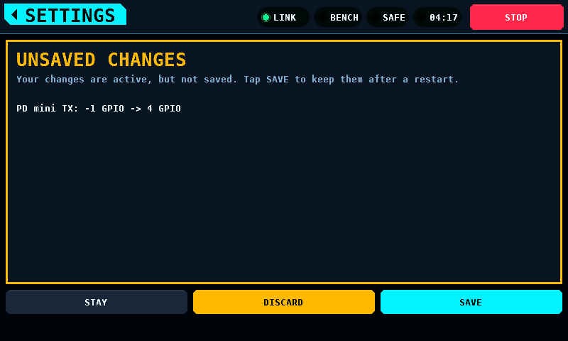
It lists each value and string that differs from the stored copy, one line
of 22 px each, as name: stored -> now. A value is written as the list
writes it, with its unit; a string, the DUT (device under test) name, as it
is. Values set on other screens, such as SERVO's settings or ESC STICK's,
are listed too: they are in the same set and the same save keeps them. The
lines follow the schema's order, the strings after the values. With more
than 10 changes, 9 lines show and the tenth reads and 3 more for 12.

The strip's three columns hold the answers:
| Button | What it does |
|---|---|
| STAY | Closes the warning. The tiles show again; a list keeps its category and its scroll. |
| DISCARD | Sets every changed value back to its stored one through the path a step by hand takes, then opens the menu. |
| SAVE | Asks for a write as the save button does, then opens the menu. The write follows the same rule: the first idle frame. |
DISCARD sets each value with the same call a key does, in schema order, so the coprocessor hears each pin and port that moves, and APPLICATION's language, theme, brightness and contrast apply on the next frame. A PD mini wiring set back switches the supply output off and raises the alert a change by hand raises. PWM target and Port PWM are not set back while the servo programmer holds the servo port, as a key does not step them then; they stay unsaved. After a refused save DISCARD also asks for a write of the values put back: the medium can hold part of the refused write, and a restart would load it.
While the bench is ARMED, DISCARD is drawn inert and a line
DISCARD waits for SAFE. says why. Setting back several values at once,
pins among them, on a running bench is a change the operator did not make
in that moment. STAY and SAVE work while ARMED; a save waits for SAFE as
WHEN IDLE. The line The last save failed. SAVE tries again. shows in
the danger colour after a refused save.
The warning holds only the home tag:
- Nothing unsaved, or a save asked (
WHEN IDLE): no warning, the menu opens. - OUTPUTS, PICK A PIN and UPDATES open from a tile and return to SETUP: no warning on the way out or back.
- The home tag over the warning is STAY.
- STOP stops the bench and leaves the warning as it is.
- A screen the panel opens by itself, such as the bus-fault screen after a link loss, closes the warning at once. The values stay in force and unsaved.
The panel runs the CAN (Controller Area Network) echo self-test at every start-up, for 1200 ms inside the splash. A verdict other than every probe coming back intact puts this on the panel instead of the menu.

It exists because the fault is invisible from every other screen: a bus that does not carry frames looks exactly like a coprocessor that is not fitted, and both look like a bench that shows no numbers. The verdict is the heading, the list is what to check in the order that costs least to check, and the right column is what both ends counted.

Leaving it takes a two-second hold, the ARM gesture and the same fade. Acknowledging repairs nothing: the bench runs in simulation, nothing drives an output, and the test runs again at the next start-up. There is no band and no STOP, because the bench cannot switch to ARMED behind it.
The same screen carries the other half: a link that was up and has been gone for 4 s. The heading is what this panel's own CAN controller is doing, because the wire carried frames a moment ago.

| Heading | Meaning |
|---|---|
this panel is off the bus |
too many frames went unacknowledged; it stopped transmitting |
this panel is rejoining |
it is counting the quiet time a rejoin needs, about 3 s |
the controller has stopped |
idle and not restarted — a fault in the firmware |
the link stopped answering |
the controller is on the bus and nothing answers |
the controller cannot be read |
the driver is not running; nothing can be sent |
Four seconds, not one: the link drops for a poll now and then, and a screen that took over on every blip is a screen operators learn to dismiss.
Never while ARMED. The screen has no STOP, and a bench with something spinning must not have its stop button covered by a diagnosis. While ARMED, the alert band says the link is gone and the screen waits for the switch to SAFE.
The same numbers go to RCBENCH.LOG on the SD card, one line per report while
the link is down:
t=182s link=down for 47s bus=OFF tx_err=248 rx_err=0 bus_err=1976 rejoins=44/44 polls=5323 replies=5279 timeouts=44
The fields are the same in the same order every time. rejoins is this outage
over the total since boot, and an unreadable controller writes ? in its
columns rather than a differently shaped line: the reading that most needs a
timestamp is the one where the controller would not answer.
The card is there because the panel's console is not reachable on every board. The native USB socket carries GPIO19 and GPIO20, which the multiplexer hands to CAN about a second into boot, so it is gone before a bench fault happens. The bridged socket is on UART0 and normally carries the console right through, but what it is connected to is switchable: a slide switch beside the BOOT and RESET buttons is marked UART1 and UART2. In one position the bridge chip enumerates and passes nothing in either direction, and the panel then has no console at all.
Bringing up the link has the verdicts and what each one means.
A panel built with the coprocessor's image carries it and offers it when the
coprocessor runs another build. The check runs at every link-up and compares
SHA-256 (Secure Hash Algorithm) digests, not version numbers. A different
build raises the alert coprocessor runs another build -- the menu offers its update, and the question opens on the menu while the bench is SAFE, the
supply's output is off, the panel's Wi-Fi radio is wholly off and no install
of a panel image is under way. A START given while either holds is spent,
and the question opens again once both have ended.
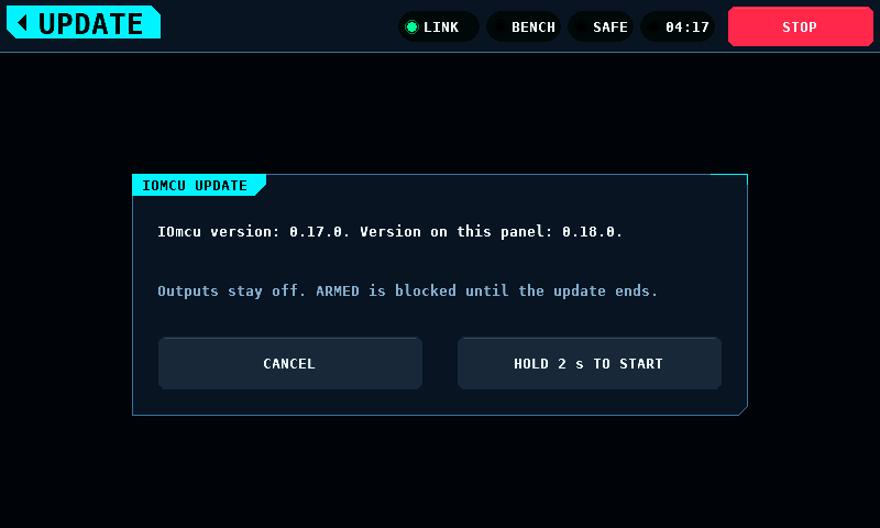
The question names the version the coprocessor runs and the version this panel carries. CANCEL is a tap: the question closes, and the panel does not ask again for that coprocessor version until it restarts. Leaving the question another way declines the same way. START takes the 2 s hold, the ARM gesture and the same fade.
An older image is offered too. The question then says The image this panel carries is older. in the warning colour, and START takes the same hold.

Once START's hold completes, the update has the panel to itself: the link to the coprocessor goes down, the outputs are off, the coprocessor refuses ARM until the update ends, and the progress fills the screen. It has no band and no STOP, as the bus-fault screen has none: the bench cannot switch to ARMED behind it.
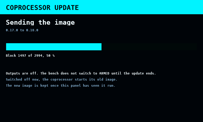
| Step | Shown while |
|---|---|
Preparing the image |
the panel hashes the image, 8 KiB a step |
Sending the image |
the blocks go out, 64 bytes each; the bar and Block 1497 of 2994, 50 % count them |
Coprocessor checks the image |
the coprocessor hashes the slot it wrote |
Coprocessor starts the new image |
it restarts into the new slot, on trial |
Keeping the new image |
the panel reads the new image's identity and writes BUY |
The screen returns to the menu when the update ends. The alert band then says how it ended:
| Alert | Meaning |
|---|---|
coprocessor updated to 0.18.0 |
the new image runs and is kept |
coprocessor update stopped: no answer -- the old image runs |
nothing answered for 4 s |
coprocessor update stopped: refused, error 6 -- the old image runs |
the coprocessor refused a step; the error numbers are in Link |
coprocessor update stopped: image check failed -- the old image runs |
the SHA-256 of the slot is not the image's |
coprocessor update stopped: flash stayed busy -- the old image runs |
the store's gate stayed shut for 10 s |
coprocessor update stopped: coprocessor restarted 3 times -- the old image runs |
three starts from block 0 |
coprocessor update stopped: new image did not start -- the old image runs |
no identity from the new image within 12 s; the boot ROM goes back to the old one |
coprocessor takes no update over CAN -- load it once over USB |
a coprocessor without the update pages or without the partition table (First run) |
coprocessor's new image kept |
an image found on trial at link-up was bought |
Power off during the update: the coprocessor starts its old image, and the next link-up offers the update again. The update writes the slot the coprocessor does not run from. Link has the transfer, the flash layout and the limits. The transfer time is not measured.
The question opens from the menu rather than from LOGS: the offer comes with the link, and LOGS is about the SD card.
UPDATES asks GitHub which panel firmware release is the newest, and installs it. It opens from the UPDATES tile on SETUP, and its home tag leads back there. A reminder at start asks the same question once per start of the panel.
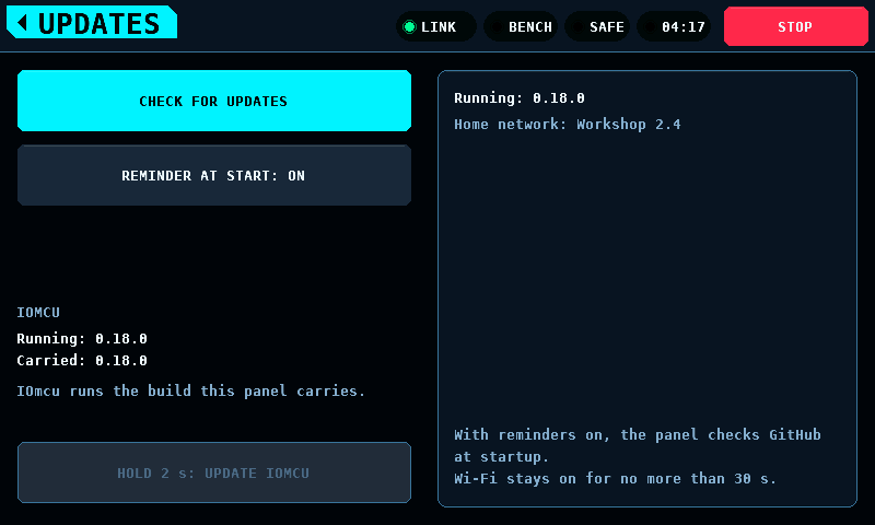
| Control | Action |
|---|---|
CHECK FOR UPDATES |
Asks GitHub once. CANCEL on the same key while the check runs. |
REMINDER AT START: ON / OFF
|
Switches the start-up check and its reminder. Kept with SAVE on SETUP, as every setting. On by default. |
HOLD 2 s: DOWNLOAD & INSTALL |
Shown once a check found a newer release. Downloads, checks and installs it. |
The card names the running version and the kept home network. Both the check and the download need:
- a home network kept on FILES & UPDATE (Home network).
Without one, the card says
No home network kept.andKeep one on LOGS > WI-FI., and CHECK FOR UPDATES is grey; - the bench SAFE, the supply output off and no log run open. Otherwise the
key is grey and the card says
Wi-Fi needs SAFE, the supply offandand no log run open.; - no update of the coprocessor running and no panel install under way.
The download needs, as an install does, no board drawing being fetched or kept.
The panel joins the home network, sends one HTTPS (HTTP over transport layer
security) request to https://github.com/subtilitas/rcbench/releases/latest
and reads the Location header of the answer, which names the newest
release's tag (.../releases/tag/v0.20.0). The answer's body is not read.
Then the radio goes off. The join, the address and the request take 30 s at
most, together.
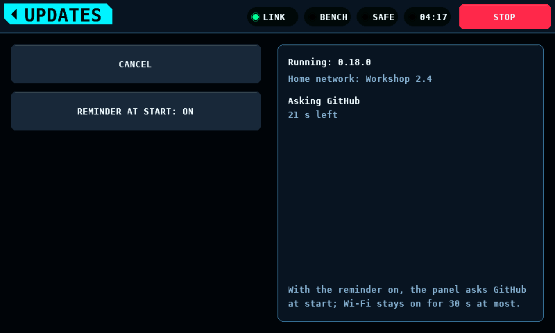
The card shows the step (Joining Workshop 2.4, Asking GitHub) and the
seconds left (26 s left). The result stays on the card until the next
check:

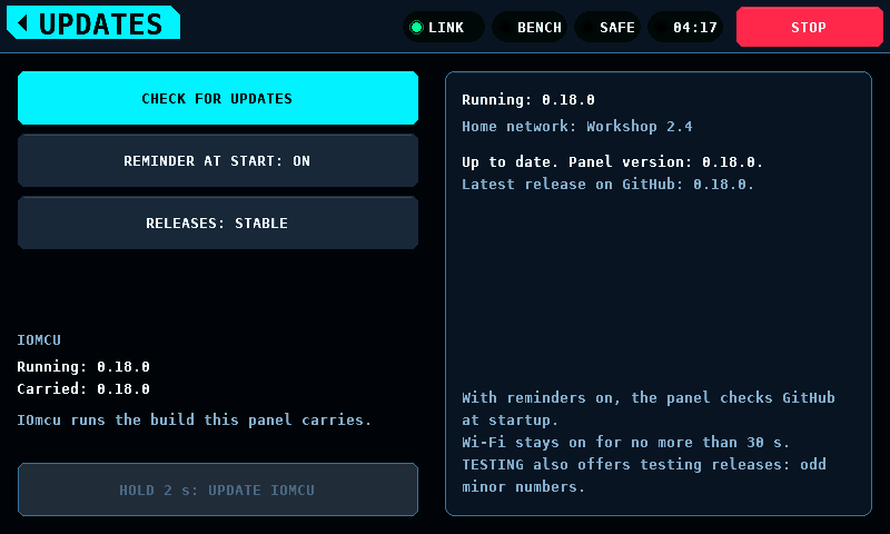
| Card | Meaning |
|---|---|
Version 0.20.0 is available. |
The newest release is newer than the running build. The hold appears. |
Up to date: this panel runs 0.19.0. and Newest release on GitHub: 0.19.0.
|
The newest release is the running version or older. |
Join failed: password refused., Join failed: network not found., Join failed: no address in 15 s., The home network went away.
|
The join failed, as on FILES & UPDATE. |
No answer within 30 s. |
The 30 s ran out. |
No connection to GitHub. |
The name lookup, the connection or the certificate check failed. |
GitHub refused: HTTP 404. |
An answer other than a redirect. |
Unexpected answer from GitHub. |
The Location is missing or out of form; a second line says which (table below). |
Wi-Fi went off: ARMED., ...: supply output on., ...: a log run opened., ...: STOP.
|
The check ended for that. |
Stopped: FILES & UPDATE took the radio. |
FILES & UPDATE opened. |
Stopped: the coprocessor's update began. |
The coprocessor's update began. |
Stopped: CANCEL. |
CANCEL. |
Wi-Fi did not start. |
The radio did not come up. |
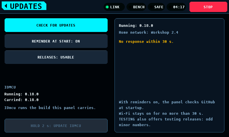
The version text is read strictly: v, then MAJOR.MINOR.PATCH, digits only,
each number from 0 to 65535 in at most 5 digits and without a leading zero
(v0.20.0, not v0.020.0), and nothing after it. A release is newer when
its MAJOR is higher, or MAJOR is equal and MINOR is higher, or both are
equal and PATCH is higher.
| Second line | Meaning |
|---|---|
No Location in the answer. |
The redirect carries no Location. |
An address over its length bound. |
A Location longer than 69 bytes: the tag address and 18 bytes. |
A byte outside printable ASCII. |
A space, a control character or a byte above 126. |
An address in an unexpected place. |
Not https://github.com/subtilitas/rcbench/releases/tag/.... |
The version text is out of form. |
The tag fails the rule above. |

With REMINDER AT START on and a home network kept, the panel runs the check once after each start. It waits for a moment the bench allows: the splash gone, the bench SAFE, the supply output off, no log run open, FILES & UPDATE closed and no coprocessor update offered or running. A start-up check that has found no such moment 10 min after the start does not run at that start.
When the check finds a newer release, the reminder opens on the menu (OVERVIEW). It does not open while the bench is ARMED or an arm waits, while the supply output is on, or while the coprocessor's update question or its progress is up: those come first, and the reminder opens once they have gone and the menu shows.
| Control | Action |
|---|---|
IGNORE NOW |
Closes the reminder until the next start of the panel. Leaving it by the HOME tag does the same. |
NEVER REMIND ME |
Switches REMINDER AT START off and asks for the save, which happens at the next moment the settings may be written (Keeping the values). SETUP > UPDATES switches it on again. |
HOLD 2 s: DOWNLOAD & INSTALL |
The same hold as on UPDATES. |
The start-up check shows nothing when it finds no newer release or fails. Its result is on UPDATES.
The 2 s hold is the one confirmation: no question follows the download. The
panel joins the home network within 30 s, then fetches two files of the
release's tag over HTTPS, SHA256SUMS and rcbench-panel-v0.20.0.bin.
GitHub answers each with a redirect to its file host; the panel follows at
most 3 redirects, and only to github.com, release-assets.githubusercontent.com
and objects.githubusercontent.com. Then:
-
SHA256SUMSis 4096 bytes at most, and holds exactly one line for the image's file name. - The image announces its size before a byte is kept. An image without a size, of 0 bytes, or larger than the slot (4,063,232 bytes) is refused. The image is kept in PSRAM (pseudo-static random-access memory).
- The image's SHA-256 (Secure Hash Algorithm, 256 bits) must equal its line
in
SHA256SUMS. - Every check an uploaded image passes (Installing) runs, and the image must name the release's version.
Only then does the install start, as INSTALL starts it: the radio off wholly, the write, the restart, the trial start. From the hold to the write, nothing touches the flash.

| Step | Shown while |
|---|---|
Joining Workshop 2.4 |
the join and the address |
Reading SHA256SUMS |
the first file |
Downloading the image |
the image; the bar and 720896 of 1843200 bytes (39 %) count it |
Checking SHA-256 and the image |
the checks |
CANCEL ends the download. The download also ends on STOP, on ARMED, on the supply output coming on, on a log run opening, on a board drawing being fetched, and after 180 s from the hold. The running build stays, and CLOSE goes back to UPDATES, or to the menu when the hold was the reminder's.

| Line | Meaning |
|---|---|
SHA256SUMS not usable. |
SHA256SUMS missing (HTTP status 404.), over 4096 bytes, A line out of form., No line for the image. or The image on two lines.
|
SHA-256 differs from SHA256SUMS. |
The image is not the one the release lists. |
The image failed the panel's checks. |
One of the image checks refused it. |
GitHub refused: HTTP 404. |
An answer to the image other than the file or a redirect. |
Unexpected answer from GitHub. |
More than 3 redirects., A redirect to an unlisted host., An address over its length bound. (a Location over 2048 bytes), No size announced., An empty answer., Larger than the panel takes., Shorter than its announced size., The image names another version.
|
No memory for the image. |
PSRAM had no room for the announced size. |
No answer within 30 s., No answer within 180 s.
|
The join's 30 s or the download's 180 s ran out. |
Current limitations:
- The check's and the download's durations on a real network are not measured.
- No certificate's dates are checked: the panel has no clock.
- A release whose assets are not named
rcbench-panel-vX.Y.Z.binandSHA256SUMScannot be downloaded.
Behind the OUTPUTS tile on SETUP; its home tag leads back there. The protocols bound to the coprocessor's pins, and which pins each one drives.

A set of pins per protocol, not eight independent slots: a bench is wired a protocol at a time — four servo leads, then one ESC (electronic speed controller) — and asking for the protocol and then for its pins is the shape of that job. More than one protocol can be bound at once, and a pin belongs to at most one of them.
Each ticked pin becomes one slot on the OUTPUTS page, in pin order across every protocol, taking channels from zero upward — so the lowest ticked pin is channel 0 whatever order the screen was touched in and whichever protocol holds it. Eight slots and eight channels are the budget, shared. PPM renders eight channels on its one pin, so a bench with PPM on it has room for nothing else. It runs at 40 Hz, not the 50 Hz the pulse drivers use: eight channels need 23,300 us of frame and 50 Hz gives 20,000.
SERVO PWM and MOTOR PWM are the same pulse at the same 50 Hz and differ in what the channel is for. A servo channel centres when nothing commands it; a motor channel stops. Nothing in the pulse says which is on the pin, so the entry says it: bind an ESC as MOTOR PWM and a control surface as SERVO PWM. The MOTOR & ESC throttle drives every channel bound as a motor — MOTOR PWM and the DShot entries — and leaves the servo channels alone.
A MOTOR PWM channel sends 0 % throttle as the Idle pulse and 100 % as the
Full pulse: 1000 us and 2000 us by default, set under SETUP, ESC / BENCH, in
steps of 10 us (Idle pulse 800 to 1600 us, Full pulse 1400 to 2400 us). The
two settings reach the channels bound as a motor and no others: a SERVO PWM
channel keeps 1000 to 2000 us, or the range the SERVO screen sends for the
servo chosen there. An edit reaches the coprocessor 300 ms after the last
change while the bench is SAFE; one made while it is ARMED waits for the
switch to SAFE. A coprocessor that links up is brought to the two settings before
the bench drives it: with the bench already ARMED, the coprocessor is held
SAFE until it has them. An Idle pulse that is not below the Full pulse is not sent, and the
band says idle pulse must be below full pulse -- not sent.
An ESC whose throttle range was calibrated on a transmitter takes that transmitter's shortest pulse as zero. An Idle pulse above it reads to the ESC as throttle not at the bottom, and the ESC does not arm; many ESCs beep rapidly in that state. Set the Idle pulse at or below the transmitter's shortest pulse and the Full pulse at or above its longest: for a transmitter that sends 985 to 2012 us, 980 us and 2020 us.
When the protocol can take no more pins, the reason is under it in amber:
NEEDS 8 CHANNELS, 4 FREE, ALL 8 SLOTS IN USE, or SERVO PWM TAKES 8 PINS. A board drawn entirely in grey with nothing beside it reads as a
fault, and PPM greys the whole board whenever anything else is bound.

The protocol is a list rather than a stepper, because there are eight of them and stepping past seven to reach the eighth is not choosing:

Reserved pins are shown and cannot be ticked. GP3 carries the safety heartbeat and GP8 to GP12 are the CAN (Controller Area Network) controller, and each says so under its name. Hiding them would leave an operator hunting for GP10 and finding a gap. DShot and the output drivers has the whole map.
The pin of the coprocessor's programming port, GP13 by default, is shown as
PROG PORT and cannot be ticked either:

A stored binding that holds that pin keeps it: the port then has no pin, and the programmer's CONNECT ends with the line for a port without a pin (the port).
SERVO PWM and MOTOR PWM run on the PWM slices, and the coprocessor refuses two bindings there (Servo PWM). Under those two entries the screen holds such a pin, as it holds a pin of another protocol: grey, no tick, and the pin it clashes with named under its name.
| Cell | Line after a tap on it | Rule |
|---|---|---|
SLICE OF GP13 |
GP28: PWM SLICE OF PROG PORT GP13 |
the pin shares a slice with the programming port's pin while the port holds it; GP13 and GP28 are slice 6 |
PWM CH OF GP0 |
GP16: SAME PWM CHANNEL AS GP0 |
the pin shares a compare register with a pin bound as SERVO PWM or MOTOR PWM: GP0 and GP16, GP1 and GP17, GP2 and GP18, GP4 and GP20, GP5 and GP21, GP6 and GP22 |
The line stands under the protocol, in amber, until the next pick, the next
tick that lands, the next visit to the screen or a change of board. A line
on the protocol's own budget (ALL 8 SLOTS IN USE and the others) comes
first. DShot and PPM run on PIO (programmable I/O), not on a slice, and are
offered both pins.
Limitation: the slice rule needs the programming port's pin, which the panel
reads from the coprocessor. Until that reading arrives, up to 500 ms after
the link comes up or the port's pin changes, GP28 is offered, and a tap on
it ends in LAST WRITE: REFUSED. Other coprocessor checks, such as the
SERVO page's frame rate on a pin shared with MOTOR PWM, also refuse with no
reason on this screen.
The pad number under each pin is the one printed on the board, so an operator counting pads and an operator reading GPIO (general-purpose input/output) numbers arrive at the same pin.
Ticking or unticking a pin writes the binding at once. There is no APPLY key: a screen holding a choice that has not been sent is a screen that disagrees with the bench, with nothing to say which of the two is driving. The panel then reads both pages back and shows what the coprocessor holds. What became of the write is under the protocol, as LAST WRITE:
| LAST WRITE | Meaning |
|---|---|
NOT WRITTEN |
nothing has been written since the panel started, or a write was not sent because the binding on the screen was not one a read confirmed |
WRITTEN |
the coprocessor acknowledged every exchange of the write |
NO LINK |
an exchange of the write got no answer within 1000 ms, or the link was down |
REFUSED |
the coprocessor answered and refused: a pin it cannot bind, a change while the bench is ARMED, or a frame rate it could not put back |
To a coprocessor speaking protocol 4.10 the binding is written whole: the
two pages are prepared beside the ones in force and taken together by one
commit (Link). NO LINK and REFUSED then
leave the binding in force exactly as it was, except when the one
acknowledgement of the commit is lost: the binding is then in force, the
screen says NO LINK, and the read at the next link-up shows it. An older
coprocessor takes the pages one entry at a time, and a write that stops part
way leaves the entries before it in force.
Picking a protocol in the list writes nothing. It says which set of pins the screen shows as ticked and which set the next tick joins. Nothing is dropped: the pins ticked for the protocol being left stay bound, and the pins of the one arrived at come back as they were. A selector that retargeted the current pins would make binding a second protocol mean unbinding the first. On entry the list shows the lowest-numbered protocol that holds a pin, in the list's order, or OFF when no pin is bound. A protocol picked without ticking a pin stays selected across read-backs and across leaving the screen, and is the one a tap on PICK A PIN joins. The list on PICK A PIN selects the same protocol.
DSHOT600 BIDIR and DSHOT300 BIDIR are the longest entries, 14 characters:

A pin another protocol holds is drawn greyed, with that protocol's name under it where a free pin shows its pad number. That is a choice, undone by going to that protocol and unticking it there — unlike a reserved pin, which is drawn red and struck through because it is the wiring rather than a choice.
Four servo leads and an ESC, with DSHOT300 the protocol being edited. GP5 is ticked; GP0, GP1, GP2 and GP4 say SERVO PWM and cannot be ticked here; GP3 and GP8 to GP12 are red because the coprocessor reserves them:

So a cell is in one of four states, and each says what to do about it: ticked in this protocol, held by another and named, reserved and struck through, or free and showing its pad number.
OFF is the first entry of the list and binds nothing: it takes 0 pins, and
the count under it reads 0 OF 0 PINS. With OFF picked, every bound pin
shows the name of the protocol that holds it, so the whole binding is on one
screen. No pin can be ticked or unticked: a tap on a pin does nothing, and
the line under the list says OFF SHOWS ALL, EDITS NOTHING. Picking OFF
writes nothing and unbinds nothing.
OFF stays picked across read-backs, repaints and a link that goes down and comes back, until another entry is picked or the screen is left. The next entry opens on the lowest-numbered protocol that holds a pin.
GP0 bound as DSHOT600 BIDIR, GP1 as MOTOR PWM, GP2 and GP13 as SERVO PWM, with OFF picked. A slot holds GP13 on this bench, so the programming port has no pin:

With SERVO PWM picked on the same bench, GP2 and GP13 are ticked and show
PAD 4 and PAD 17: a pin ticked in the selected protocol shows its pad
number, because the protocol is the one named in the list.
The screen edits a binding only after reading it. A read gives one of four results:
| Read | The screen |
|---|---|
| both pages read and they describe a binding, one with no pin bound included | shows it and takes edits |
| a page did not read: no answer within 1000 ms, a refusal, or the link is down | keeps the last binding read, dimmed, with BINDING NOT READ - NO EDITS
|
| both pages read and no binding describes them: one pin in two slots, a rate or driver no protocol entry has, a pin off the board or reserved, channels out of slot order | keeps the last binding read, dimmed, with PAGES HOLD NO VALID BINDING and the key HOLD: UNBIND ALL PINS
|
| the coprocessor is a board this build has no pin map for | shows no pins |
In the second and third state a tap on a pin does nothing here and on PICK A PIN, and no write is sent. A tick made just before the read failed is taken back: the pins shown are the ones last read, not the ones last tapped. The list still opens, and a pick still changes which protocol's pins show their pad. The panel reads again at every link-up and every 500 ms while the link is up and the binding is not confirmed; the first read that gives a binding ends the state.

Pages no binding describes do not become readable by reading them again.
HOLD: UNBIND ALL PINS, held for 2 s, writes a binding with no pin; the
read-back then shows nothing bound and edits are taken again. It is the one
write the screen sends in this state. A finger that leaves the key, a lift
before 2 s, and leaving the screen abandon the hold.

A coprocessor older than 4.10 can be left in this state by a write that lost a frame part way. A coprocessor speaking 4.10 written by this panel is not; it shows this state only for pages another host or an older panel left in its flash.
Behind the PICK A PIN tile on SETUP, and its home tag leads back there. The same binding the Outputs screen holds. The list answers "which GPIO is bound"; this answers "where do I put the lead".

The keys are not the pads. At any size that fits a 480-pixel panel a pad is under 40 pixels across, which is smaller than a fingertip, so the pads are drawn where they are and the touching happens on two staggered rows of keys above the board and two below, 43 px wide, each on a straight trace to its own pad.
A key's colour says what a tap on it does:
| Key | Pin | A tap |
|---|---|---|
| ivory (row nearer the board) or ebony (row beyond it) | free | binds it to the selected protocol |
| accent | bound in the selected protocol | gives it back |
| grey | another protocol holds it, the programming port has it, the selected protocol can take no more pins, or the binding is not confirmed | changes nothing |
| none, red cross on the pad | reserved by the coprocessor: GP3 heartbeat, GP8 to GP12 CAN | — |
Neighbouring keys differ in height and in colour, like the keys of a keyboard. A reserved pin has no key because a key under a pin that cannot be chosen says it could be.
Top left is the protocol list, the same control as on the Outputs screen. It names the selected protocol. A tap opens it over the board; a pick selects the protocol a tap on a key joins, on this screen and on the Outputs screen, and writes nothing. A tap outside the open list closes it and picks nothing. OFF picked here ends when the screen is left, as on the Outputs screen: the next visit to either screen opens on the lowest-numbered protocol that holds a pin.
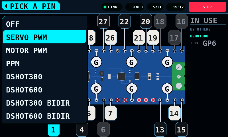
Under the list is N OF 8 SLOTS IN USE, counted over every protocol: the
protocols share the 8 slots of the OUTPUTS page. Under that, in amber, is
the reason no key can be added, in the words of the Outputs screen:
| Line | When |
|---|---|
ALL 8 SLOTS IN USE |
8 pins are bound over all protocols |
NEEDS 8 CHANNELS, 4 FREE |
PPM, which carries 8 channels on one pin, with 4 servo pins bound |
SERVO PWM TAKES 8 PINS |
the selected protocol holds as many pins as it takes |
OFF SHOWS ALL, EDITS NOTHING |
OFF is selected |
NOT READ |
the binding is not confirmed |
Without the line a board drawn all grey reads as a fault.
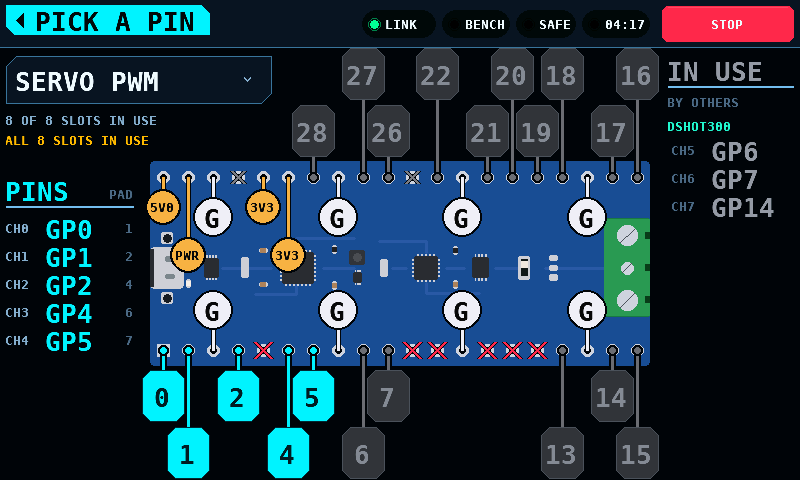
Down the left, under PINS, are the selected protocol's pins in channel order, each with the pad number printed on the board in the PAD column. Down the right, under IN USE, are the pins other protocols hold, each group named and listed where its first pin falls. The two tables together read as one run of channels, because that is what the OUTPUTS page carries.
The pin of the coprocessor's programming port, GP13 (pad 17) by default, is
drawn grey while no protocol holds it, a tap on it changes nothing, and IN
USE lists it first under PROG PORT, without a channel. A protocol whose
stored binding holds that pin keeps it, the coprocessor gives the port no pin
then, and the key is that protocol's like any other.
Under SERVO PWM and MOTOR PWM a key the coprocessor refuses on a PWM slice
is grey too, as on the Outputs screen: GP28 while the port holds GP13, and
the partner of a pin bound as PWM, GP16 beside GP0. A tap on it changes
nothing and puts the Outputs screen's line under the count:
GP28: PWM SLICE OF PROG PORT GP13, GP16: SAME PWM CHANNEL AS GP0.

IN USE lists every pin it holds. A protocol's name takes a 20 px line and a pin a 28 px line. When those run past the foot of the table, every pin line is 20 px with the GPIO in the smaller face. The tallest table is OFF selected, the programming port listed and the 8 slots over the 6 protocols that take one channel a pin: 16 lines, 320 px of the 360 px under the heading.

A tap on a key writes the binding through the same sequence as a tick on the
Outputs screen, with the same results. While the binding is not confirmed — a
read failed, or the pages describe no binding — every key is grey, NOT READ stands under the count, and a tap on a key changes nothing and writes
nothing. The protocol list still selects.
Where the pads are comes from the board, not from the panel: the shape page carries the outline, the pitch and the corner pad 1 sits at. A board that does not say is not drawn at all — a picture from a guessed shape points at the wrong pad as confidently as the right one, and this screen's whole job is finding a pad on the board in front of you. Its pins are still on the Outputs screen.
The board's drawing comes from the board as well. The coprocessor carries a drawing of itself, the one the configurator draws: the outline, the parts as flat shapes and every pad, to scale in 0.01 mm (The board drawing). The panel draws it on the shape's pad grid, so the board on screen is laid out like the board in your hands. Without a drawing, the outline and every pad are drawn from the shape and the keys are in the same places:

The panel shows a drawing only when it describes the board the panel binds: the outline and every pad position match the shape, every pin pad carries the catalogue's GPIO, and every other pad the catalogue's ground or rail. A drawing that disagrees is not shown, and the shape is drawn instead.
The drawing of the RP2350-CAN is 1,560 bytes, fetched over the link in 26 blocks of 62 bytes in a 15 ms slice of each 50 ms poll. The time this takes on a bench is not measured. The panel keeps it in its flash with the drawing's length, CRC (cyclic redundancy check) and hash, and shows the kept copy only while the coprocessor still reports the same three; a coprocessor flashed with another drawing is fetched again. Writing it to flash waits for a bench that is SAFE with the supply off and pauses between two 4 kB sectors when the bench is ARMED or the supply comes on (Safety). A board with no drawing, or one whose transfer has not finished, is drawn from the shape rather than left blank.
A servo lead has three wires and the keys describe one. The other two are marked on the board itself, on a short trace in from the pad:
| Mark | Pad |
|---|---|
| white round marker, 36 px, with a large G, 40 px in from the pad | ground |
| amber round marker, 32 px, with the voltage: 5V0, 3V3 | a rail at a fixed voltage |
| amber round marker with PWR | a rail that is an input, VSYS: a number that is only sometimes true is worse here than none |
| dim cross on the pad | neither, like RUN and 3V3_EN |
The marks go inside the outline because that is the only room left: the space beside the board belongs to the keys, and a mark on the pad itself would be as small as the pad. Rails sit on neighbouring pads, 25 px apart, so a rail's marker is 30 px or 78 px in from its pad, alternating along the row; the deeper one clears the marker of a ground on the pad beside it.
These come from the pads page, which is separate from the catalogue because they do not fit in it — a page is 32 registers and a 40-pad board has more pads than that between the two. A board that does not serve it has its grounds and rails unmarked, and a lead is placed by reading the board rather than the screen.
A binding describes wiring, and the panel is not the board the wires are in. The coprocessor writes the OUTPUTS and CHAN_CFG pages to its own flash and restores them at boot; the panel never stores a binding and never sends one unasked. When the link comes up the panel reads the page and shows what is configured over there. After a panel restart, what this screen shows and what is driving pins are the same thing.
Restoring configures the outputs. It does not drive them: every driver is gated on the pin's role being ARMED, which the coprocessor grants only while the ARM register names that role, the link is out of failsafe and the heartbeat is trusted, so a restored binding claims its pins and holds them at idle until somebody switches to ARMED. Channel commands are not restored — a configuration survives a power cycle and a throttle position does not.
The save waits for the bench to stop driving, and then for a gap in the
traffic. Writing flash stops the coprocessor with interrupts off, and it
answers nothing while it is stopped: on the bring-up module a save that
erased and programmed inside one window measured 19,178 us, against a CAN
frame of about 130 us and two frames of buffer in the controller. The figure is one
measurement: 1 sample, taken on the bring-up module, with the flash part not
yet identified. The erase and the page program have not been timed apart from
each other. The window is to be argued again against the flash part's
datasheet maximum once the part is known. A request lost
in that window costs the panel 1000 ms of waiting, which is past the
coprocessor's 200 ms silence failsafe, so one lost frame ends as FAULT 01
(LINK_FAULT_LINK_SILENT) over a cable with nothing wrong with it.
So the sector is not erased per save. Two sectors hold sixteen records each; a save writes the next record, and a sector is erased only once every record in it has been superseded. That erase is taken before the save that needs it: at boot before the coprocessor starts answering, or on a pass after the save that first writes into the other sector, once the bus has been quiet for 5 ms. It is the sector left behind that is erased, not the one just filled, so the erase and the save that needs it are separated by the fifteen saves in between. Fifteen saves in sixteen therefore cost one page program and no erase. How long a page program takes on the module's flash is not measured; the console line printed after each save carries it.
A power cut during a save leaves the binding from before it. Each record carries the number of 0 bits it holds, beside that number complemented. An erase sets bits and a program clears them, so a record caught in either holds fewer 0 bits than it claims, and the claim cannot survive a partial write in either direction. The record being written is therefore rejected rather than probably rejected, the record before it is still the newest good one, and the sector being erased is never the one holding the record still wanted.
Pages the screen cannot describe — one pin in two slots, a rate no entry offers, a pin that is not on the header — are shown as such and not as nothing configured: see A binding that is not confirmed.
Described on its own page: Balancing.
The BALANCE pane shows a fixed angle (265°) and two fixed readings (0.42 g vibration, 0.35 g mass to add) until a sensor is fitted. The MODELLED pill and the words "Not measured." stand under the readings, 20 px high and 88 px wide. The TEST RIG and AIRCRAFT panes show placement guides and carry no mark.
A screen id that names no screen draws the overview.