Ruxpin Decode TV Teddy
TV Teddy is an interactive Teddy Ruxpin children’s toy developed and sold by Shoot the Moon Products, Inc. in 1993. Shoot the Moon was founded in 1991 by David Small and Paul Rago.
Its purpose is to give children a talking friend they can hold and enjoy while watching live action home videos starring Douglas Manes. The ongoing theme was “Anthony’s Attic” where Teddy would spectate and make comments on the adventures in Anthony’s house and said attic. Each episode often featured another animated cartoon presented in the form of “edutainment.” These were created, written, and produced by Dave Wollert.
The toy itself was battery operated and its eyes also animated when speaking. The kit included a transmitter as well as a single Berenstain Bears VHS video tape. Several other tapes could also be purchased.
According to Shoot the Moon's website, two patents behind the main technology were filed: 5,808,689 and 6,040,870. The purpose being to develop a 'Method and apparatus for nesting secondary signals within a television signal." This ultimately was implemented as a single device to both decode and transmit Teddy's voice to the directly to the toy.
The voice signal is stored after the horizontal blanking interval of the video signal. This appears as an animated gradient vertical bar on the far left side of the image. This is typically not visible on traditional CRT TVs of the time, as It lives in the overscan area of the picture tube.
The decoder appears to utilize a buffer to ensure a constant stream of audio samples is fed to the onboard DAC. Although the Teddy audio used a fixed sample rate, it is still an imperfect analog signal.
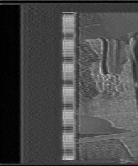
The audio subcarrier is a simple stream of brightness values, sampled once per line within the active video overscan area. Not every line has a sample, as the vertical blanking interval has to remain in tact. This limits the overall sample rate to 14,010Hz, providing about 7kHz of audio bandwidth. This is more than enough to represent speech, and all 7kHz does not appear to be used.
To be more specific, each interlaced frame has two fields with one field containing 233 samples and the other field containing 234. Each field begins with two digital bits on lines 21 and 22, with the audio starting on line 23. The first bit of the preamble is always high, likely for sync. The second bit is high when Teddy is silent and only low when Teddy is speaking and animating. The transmitter had a red power LED and a green activity LED when speaking.
 Each audio sample is approximately
the length of the colorburst. At maximum
amplitude it is at peak white, and at minimum
it is at black. Zero amplitude is gray. Dynamic
range is good, but is limited as sync level
black cannot be used, or the video signal
sync becomes corrupt. This technically may
violate the NTSC video standard, but does
not produce any adverse affects on any
consumer equipment.
Each audio sample is approximately
the length of the colorburst. At maximum
amplitude it is at peak white, and at minimum
it is at black. Zero amplitude is gray. Dynamic
range is good, but is limited as sync level
black cannot be used, or the video signal
sync becomes corrupt. This technically may
violate the NTSC video standard, but does
not produce any adverse affects on any
consumer equipment.
Software decoding of the tapes is achieved with vhs-decode & GNU Radio.
You can Download this GNU Radio Flow Graph Here
Audio Samples are also avalible Sample 1 / Sample 2
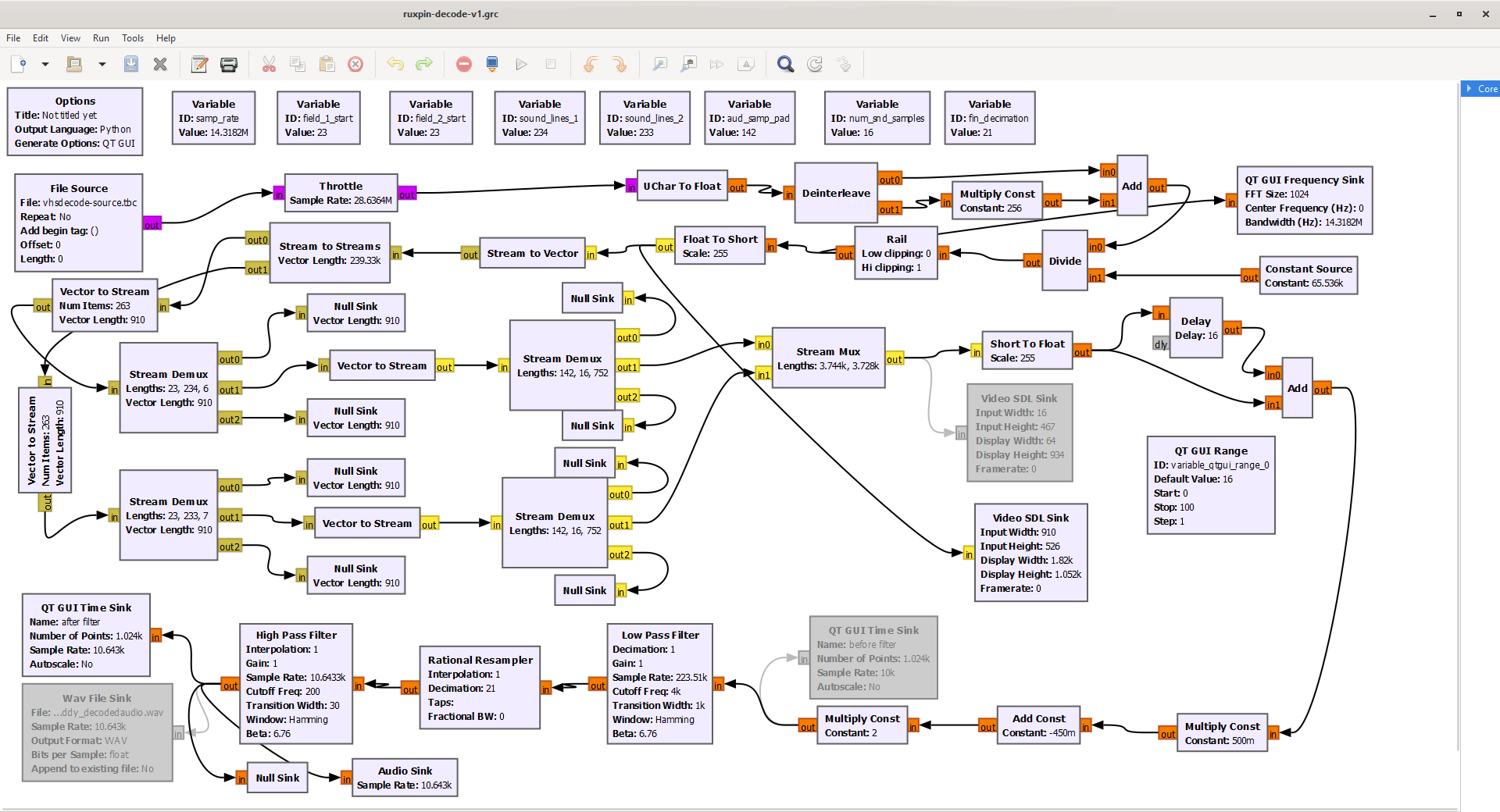
GNU Radio Companion 3.9.5.0 is used to view the flow graph and make adjustments to settings, if needed (more on adjustments later).
It takes a vhs-decode time base corrected luminance waveform (.TBC file) as an input.
Ruxpin decode then converts this unsigned 16-bit integer stream into a more standard signed 16-bit stream.
From here, the audio is sampled as 16 digital samples per analog sample and buffered in a pair of vectors which feed to a pair of stream demux blocks. Next, the data goes to a stream mux block which feeds a low pass filter, resampler, and high pass filter before feeding to the final audio sink and WAV file sink.
The final filtered and resampled WAV file sample rate is approximately 10kHz.
Optional QT GUI and video SDL sinks can also be enabled for further real time analysis, but only one video SDL sink can be enabled at a time. The flow graph decodes in real time at 1x playback speed.
For best results, it’s recommended to run the luminance TBC file through the ld-dropout-correct utility before decoding audio with Ruxpin decode. This will mask pops, crackles, and static caused by tape dropouts. The dropout correction process substitutes a line with dropouts with the last known good line.
Ruxpin decode may not produce ideal results at first. Because of the nature of analog video, you may get a high pitched noise or buzzing/crackling sounds. Three main factors can cause this: field order, phase alignment, and head switching.
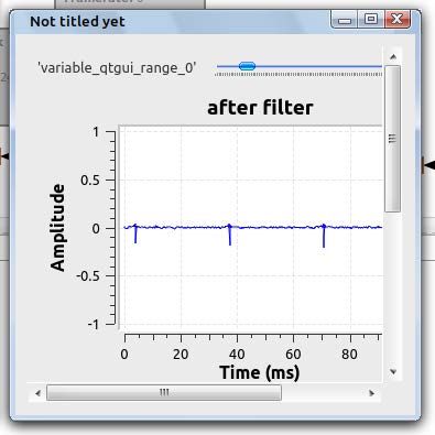
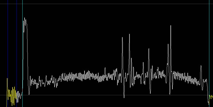
The flow graph assumes a specific field order (even/odd or odd/even). If the field order is incorrect, this can cause a 30Hz popping or buzzing sound. If you are hearing this in the output, you can look for spikes in the QT GUI time sink. If you see spikes, this confirms the field order is wrong.
To correct this, reverse the values of the sound_lines_1 and sound_lines_ variables (swap 233 and 234, essentially).
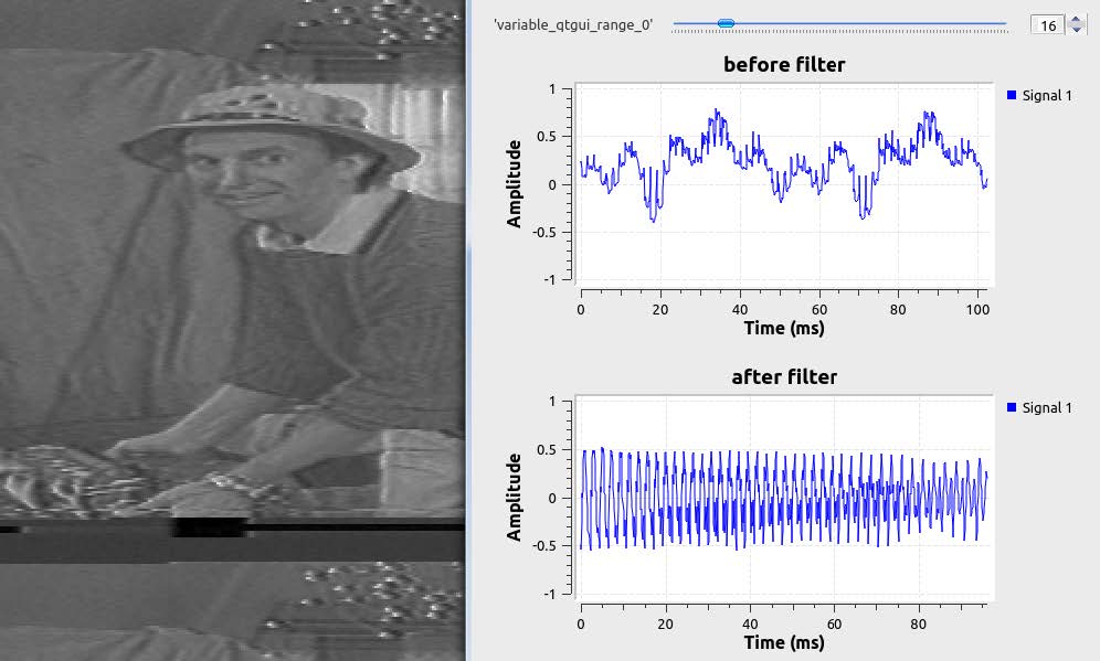
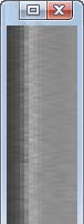
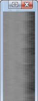
Phase alignment is also critical. This ensures the 16 sample points per line are lined up with the beginning and end of the audio sample period in the video signal. Simply, the bar for the audio needs to be lined up horizontally. The vertically stacked video SDL sink can be used to visually inspect this. When the alignment is off, a high frequency tone can be heard.
To correct this, adjust the value of the aud_sample_pad variable. Then run the flow graph. Repeat this process until the bar is perfectly centered in the preview and the noise is gone.
Too Far Left / Centered / Too Far Right

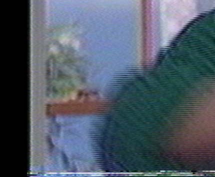
VCR video head switching is necessary to obtain a seamless RF signal from the tape. When this switch occurs, a small amount of distortion is created on the bottom of the image. The distortion is due to the time base corrector adjusting to the opposite head. The timing is VCR specific.
The head switch distortion must be several lines below the last line in the audio signal. If it is too close, noise will result. 4
Original concept and technology: Shoot the Moon Products, Inc., YES! Entertainment
9954tony on lddb.com forums / DD86 Discord
titan91 on lddb.com forums / videohelp.com forums / DD86 Discord
This flow chart and people involved in its development are not affiliated with Shoot the Moon Products, Inc., YES! Entertainment, or Family Home Entertainment.
This is a 100% “clean room” reverse engineering effort based purely on guess work, as the publicly available patents also lack the fine detail needed to reproduce the technology in software.
The patents are listed in this documentation for background purposes only.
This flow chart may be freely redistributed and modified, and is unlicensed.
“Decoding TV Teddy – Part One: Discovery” Live / Archive
“Decoding TV Teddy – Part Two: Programming and Audio Output” Live / Archive
“VHS VCR Talking Teddy Bear” Live / Archive
“TV Teddy Featured on the BBC”