Clockgen Mod
Previous Page CX Cards
Sub-Page RF Capture Guide
Next Page Hardware Installation Guide
This doc is a 1 page version of Rene Wolfs "cxadc-clock-generator-audio-adc" clockgen mod setup wiki which is flushed out with more theory, this doc focuses on the basics of what goes ware and how to actually make captures, and also features the sane use of the SMA connector, there is also a spin off of this just using wires and a Pi Pico on its own.
Important
This Guide Assumes you have CXADC Installed and have tested your cards before starting modification of them and know the basics of capture with a CX Card, and have at least overview info about its mods, the clockgen + ADC mod assumes external amplifiers are employed for optimal signal to noise ratio of the raw signal's intended to be captured.
Important
C31 Mod & BNC Mod is normally recommended and assumed deployed with this mod.
Synchronised capture is all scripted into a single .sh file to run it simply download it and define the output path
Example:
./cxadc-vhs-sync-capture.sh /home/harry/Desktop
The Resulting Output:

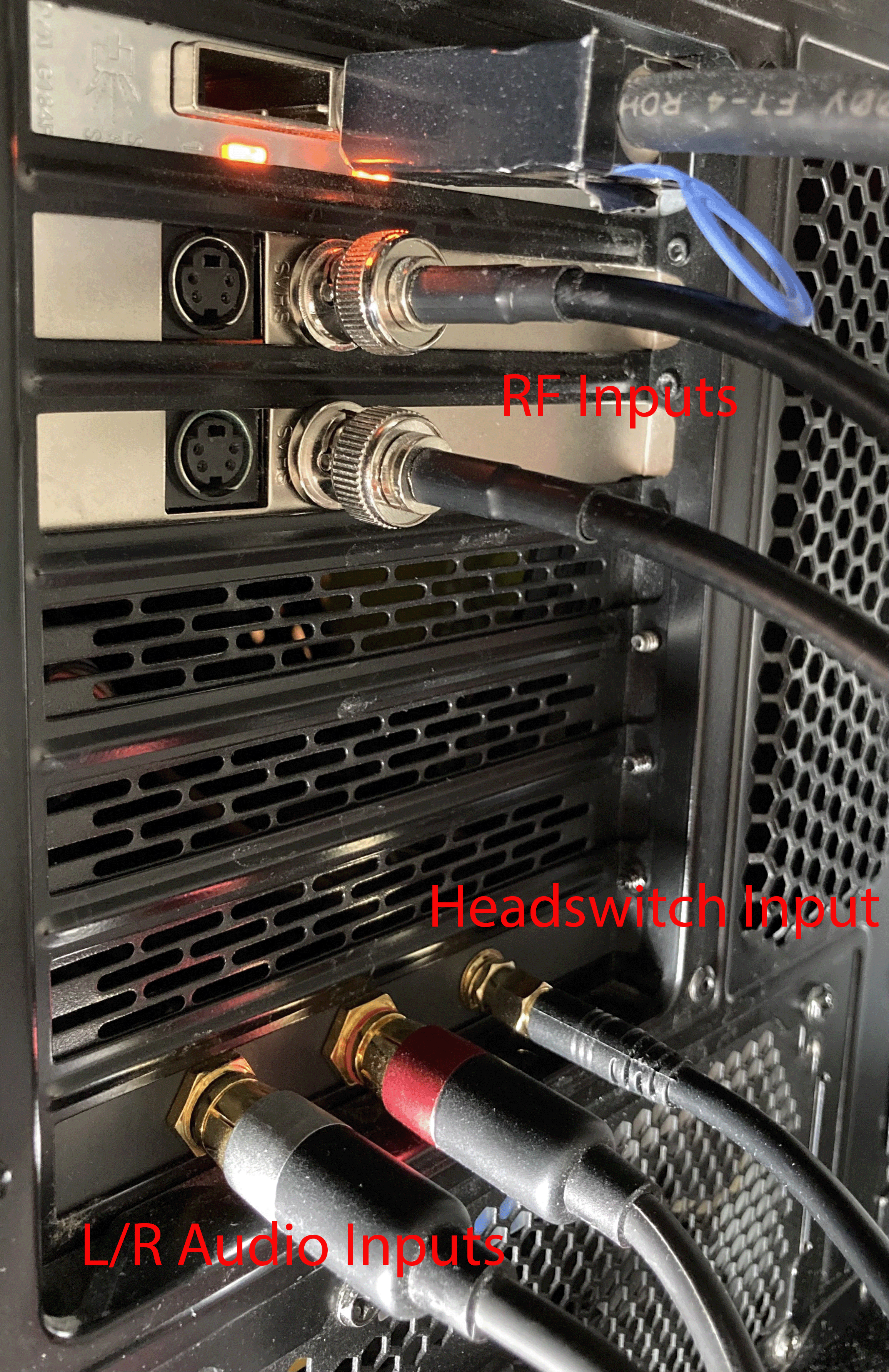
RF Output is:
xxxx.xx.xx-xx.xx.xx-rf-audio-10msps.u8
xxxx.xx.xx-xx.xx.xx-rf-video-40msps.u8
Audio is 24-bit 3 channel 46875sps (46khz) file the mapping is:
Left/Right/Headswitch
You will want to map this to 2 separate audio tracks for muxing into a final video file.
The file set is automatically date stamped yyyy.hh.dd-hh.mm.ss
After decoding your Video RF and or HiFi FM audio you will want to sync your PCM audio data with your video file
With a standard configuration you just need to alter the following:
-
-i baseband.wave- Input PCM Audio File -
--json capture.tbc.json- Input TBC JSON from decoding -
baseband_aligned.flac- Output name at the end (also s16 will do 16-bit if s24 is replaced)
"ffmpeg.exe" -i baseband.wav -filter 'channelmap=map=FL-FL|FR-FR' -f s24le -ac 2 - | mono VhsDecodeAutoAudioAlign.exe stream-align --sample-size-bytes 6 --stream-sample-rate-hz 46875 --json capture.tbc.json --rf-video-sample-rate-hz 40000000 | ffmpeg -f s24le -ar 46875 -ac 2 -i - -af aresample=48000 -sample_fmt s24 baseband_aligned.flac
"ffmpeg.exe" -i baseband.wav -filter_complex "[0:a]channelsplit=channel_layout=2.1:channels=FL[FL]" -map "[FL]" -f s24le -ac 1 - | mono VhsDecodeAutoAudioAlign.exe stream-align --sample-size-bytes 3 --stream-sample-rate-hz 46875 --json capture.tbc.json --rf-video-sample-rate-hz 40000000 | ffmpeg -f s24le -ar 46875 -ac 1 -i - -af aresample=48000 -sample_fmt s24 baseband_aligned.flac
You need to install mono
ffmpeg -i baseband.wav -filter 'channelmap=map=FL-FL|FR-FR' -f s24le -ac 2 - | VhsDecodeAutoAudioAlign.exe stream-align --sample-size-bytes 6 --stream-sample-rate-hz 46875 --json capture.tbc.json --rf-video-sample-rate-hz 40000000 | ffmpeg -f s24le -ar 46875 -ac 2 -i - -af aresample=48000 -sample_fmt s24 baseband_aligned.flac
ffmpeg -i baseband.wav -filter_complex "[0:a]channelsplit=channel_layout=2.1:channels=FL[FL]" -map "[FL]" -f s24le -ac 1 - | VhsDecodeAutoAudioAlign.exe stream-align --sample-size-bytes 3 --stream-sample-rate-hz 46875 --json capture.tbc.json --rf-video-sample-rate-hz 40000000 | ffmpeg -f s24le -ar 46875 -ac 1 -i - -af aresample=48000 -sample_fmt s24 baseband_aligned.flac
Sample rate modes are the following:
28.63msps, 20msps, 40msps, 50msps
To open the terminal control window use:
alsamixer
Press F6
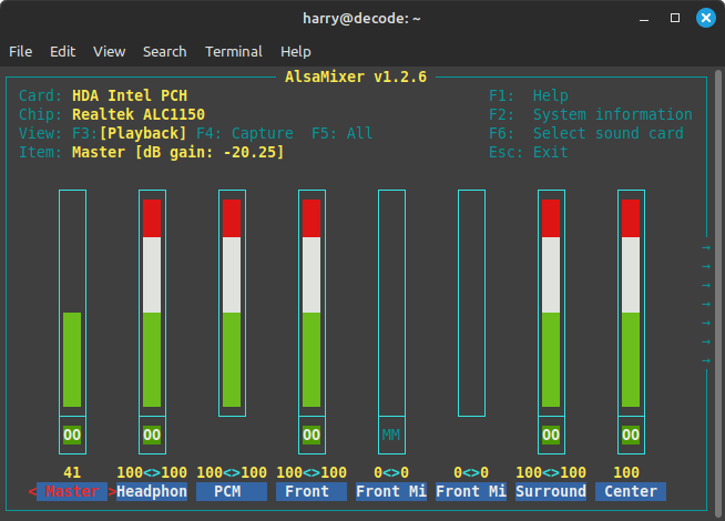
Navigate with ↑ & ↓ keys.
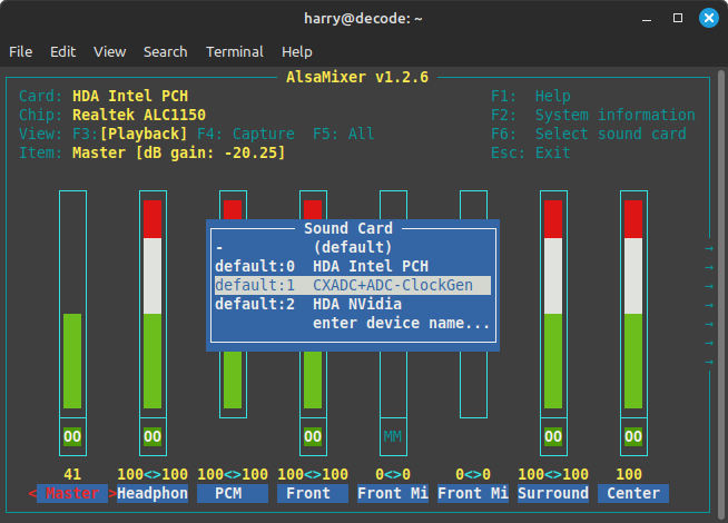
Hit Enter with CXADC+ADC+ClockGen selected.
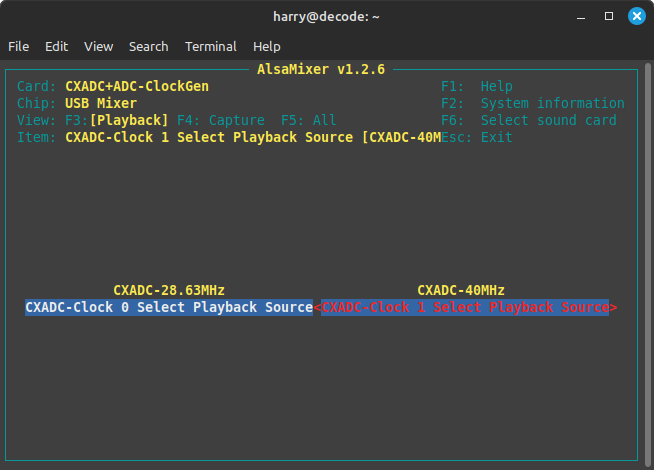
Press Space to enable audio control.
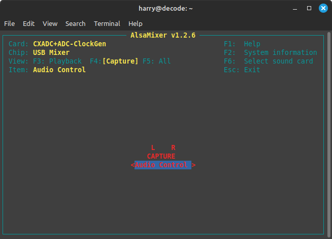
That is about it, you only play with these settings when doing manual overrides for stock settings.
Install asmixer
sudo apt install asmixer
Run alsamixer with:
alsamixer
Fix Capture Script Permissions
chmod +x cxadc-sync-capture.sh
Test Firmware / Clock Gen Firmware / Reset Firmware
Ensure Pi Pico is not plugged into the mainboard of the clockgen.
Equip a USB-C or Micro-B cable depending on your Pi Pico Type.
The Pi Pico displays as a USB storage device, simply drag and drop the test firmware onto the filesystem and it will automatically flash, if the unit blinks then its all good to reset and proceed.
To reset an Pi Pico Hold the button on it while unplugged then plug into usb, and use the flash_nuke.uf2 file to reset it to clean.
After a successful flashing this will show up as a microphone 3ch 48khz device to any systems sound manager application.
Internal USB headers can be used for the data connection to the Pi Pico
Normally PC's and Servers have internal USB 2.0 header's for basic devices.
As the audio ADC is unbalanced, and the clock gen board is sensitive to EMI due to high frequency clock signals being generated its recommended to shield the setup.
You can print a PCI bracket or you can drill out metal brackets.
Copper Tape + 3D Printed Case
Check USB Devices with
lsusb
Check PCI & PCie Devices with
lspci
Test
arecord -D hw:CARD=CXADCADCClockGe -c 3 -r 46875 -f S24_3LE --samples=1000 test.wav
Result
arecord: main:831: audio open error: Device or resource busy
Solution:
Restart, try again
PC Wont boot
This can be 2 key issues, bad SMA cable, or bad jig.
The Jig boards for the CX Cards are very sensitive, if a board is damaged or component then the board will not work.
Solution:
Reflow parts, if fail use another board, or replace all SMD components on PCB Jig.
PCB Fab - Here's the Gerber's I like PCBway but you can use JLCPCB or any domestic fab house or make them at home even have fun!
Is it worth using a PCB fab to populate parts? no not really doing it yourself is very easy and the price of having 2 boards populated, you can buy the tools and learn a invaluable skill, if not physically able then you can also ask in the discord or send off a email to Harry the community is always happy to help get hardware in hands.
Cables:
- 2x 50Ohm SMA to SMA 30-50cm Cable
- 1x 50Ohm SMA to BNC bulkhead 30-50cm.
- 2x BNC to BNC 50Ohm cables (Video RF + HiFi RF)
- 1x RCA or XLR to RCA cable (Linear or HiFi Ref)
Tools:
It's worth reading the Hardware Installation Guide if your new to soldering and or tools of the trade.
- 3rd Arm Clip Holder or Vice Clamp
- Soldering Iron / Bevel Type Tip
- 60/40 Leaded Solder (i.g Silverline or equivalent)
- Side Cutters
- 99.9% IPA
- Desoldering Gun or ENGINEER SS-02 Solder Sucker
- Desoldering braid
Parts:
-
C- Capacitor -
D- Diode -
R- Resistor
Part Sizes
- SMA's are edge mount style connectors.
- SMD SOD-123 - Diodes
- 0805 SMD - Resistor & Capacitor
Important
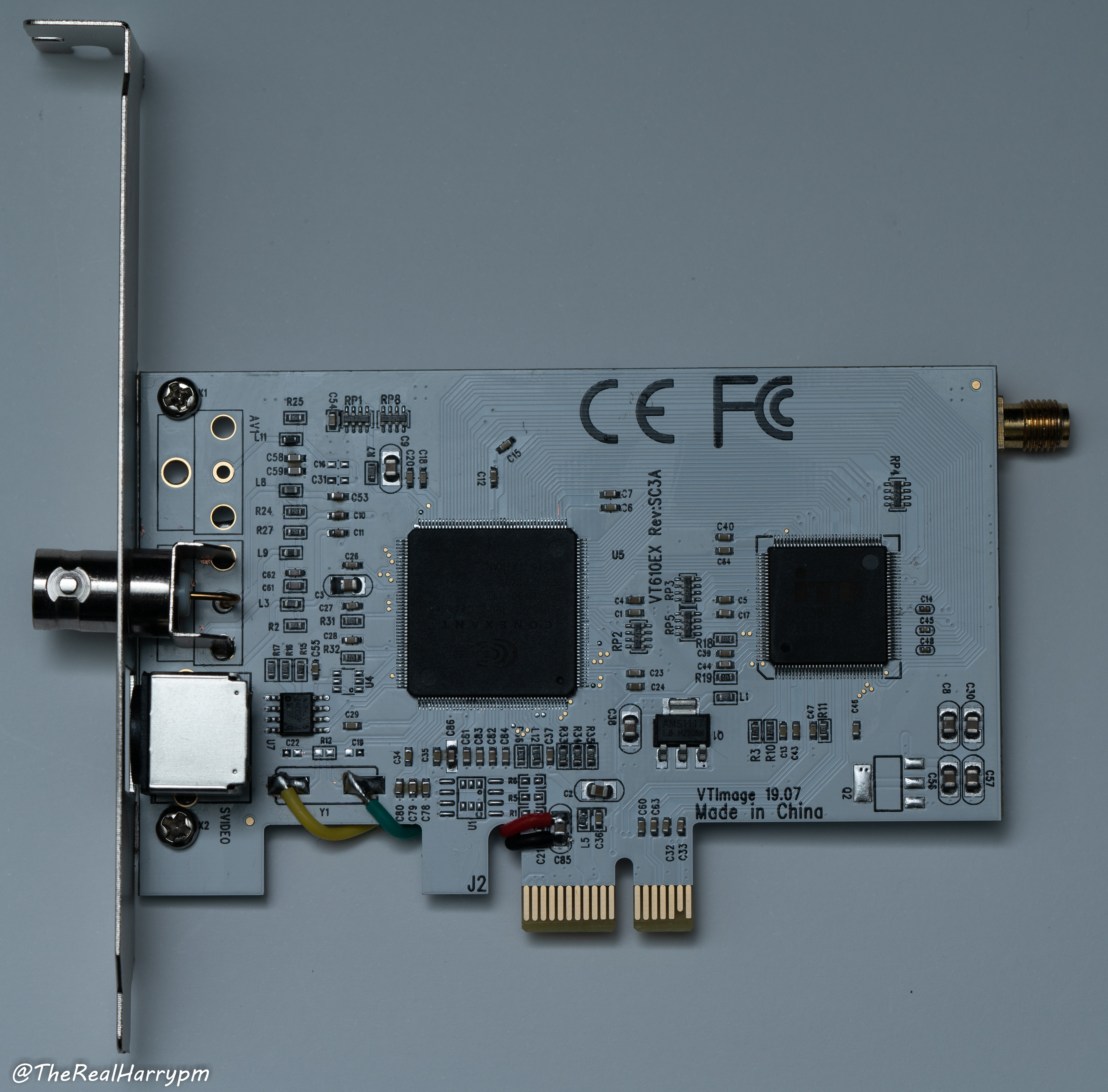
Ensure that the 3 parts C22, R12, C19 below the crystal package are removed.
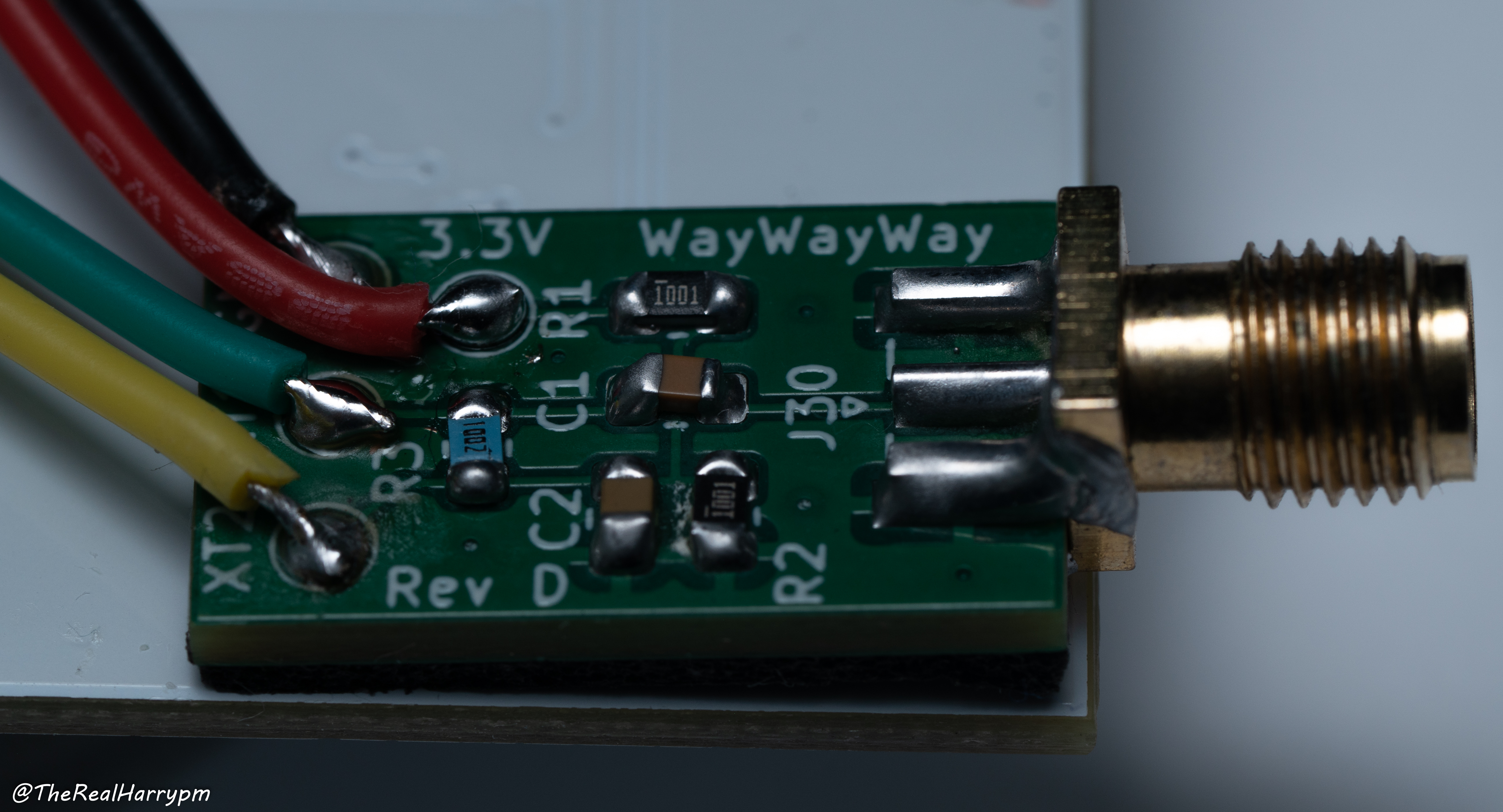
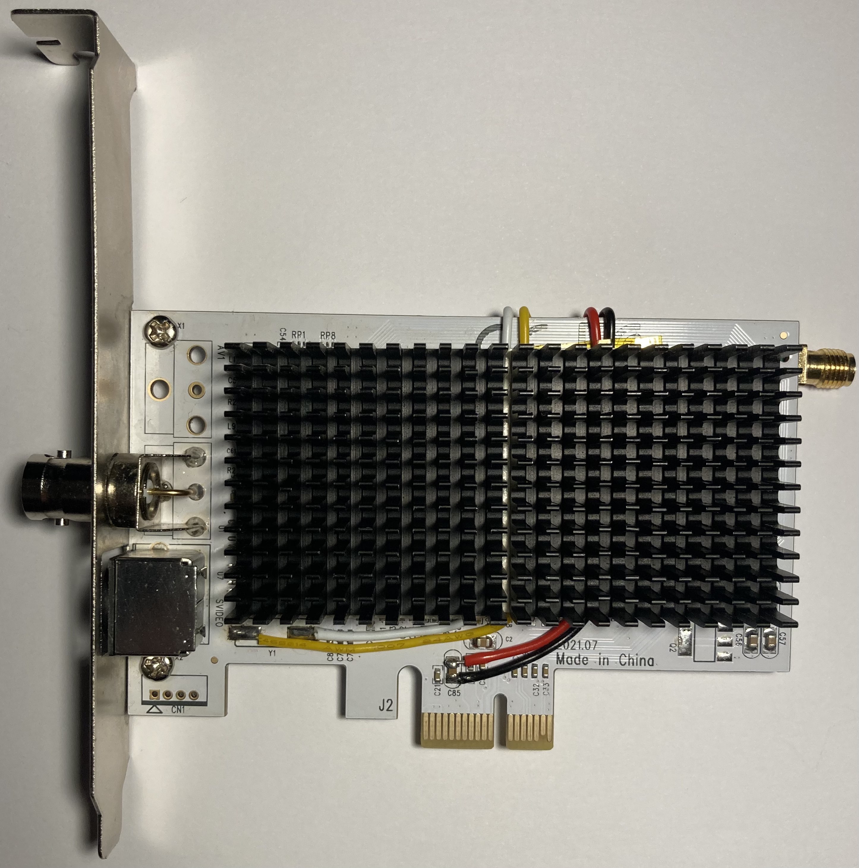
Front & Back
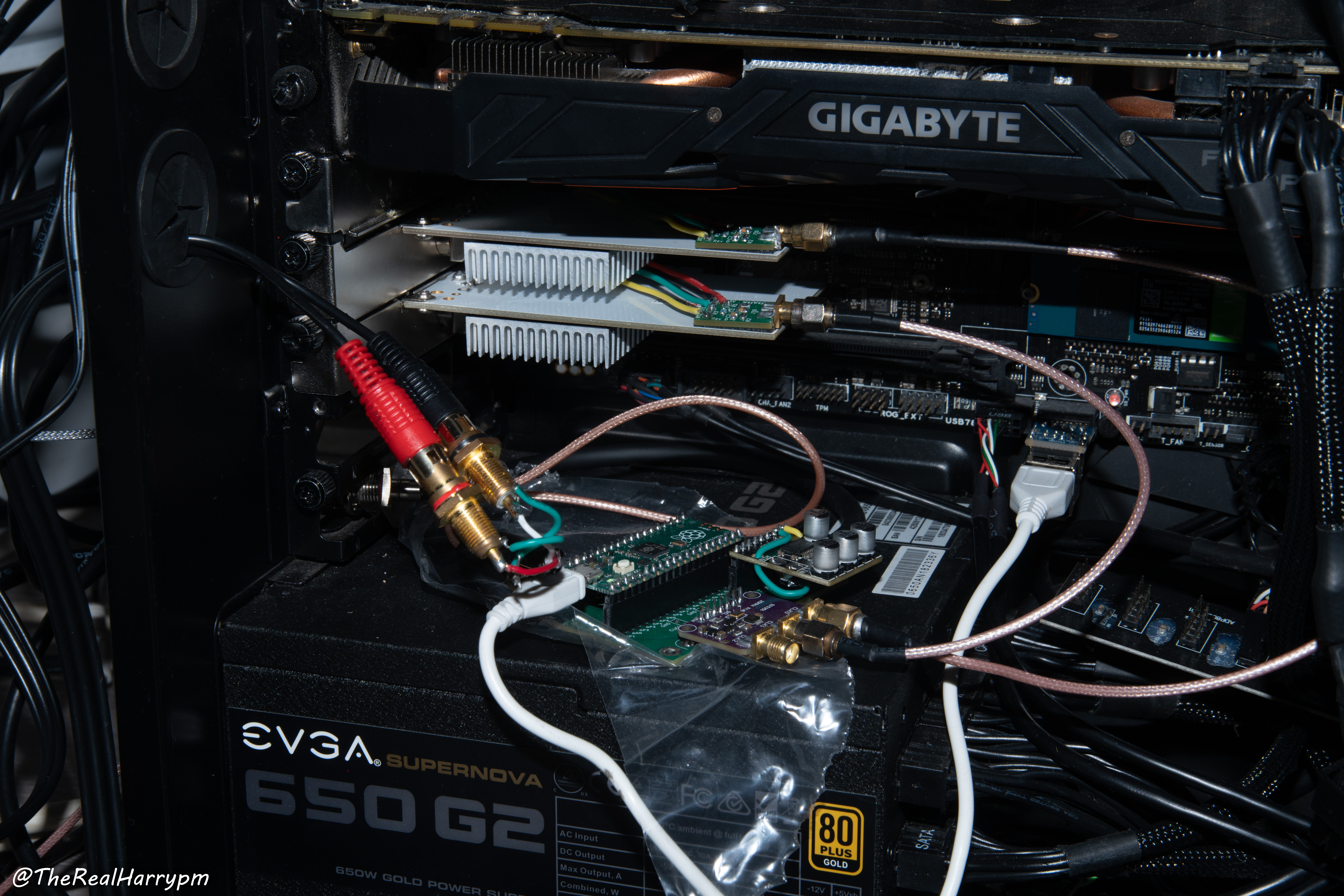
Deployed (With and without 3D printed bracket)
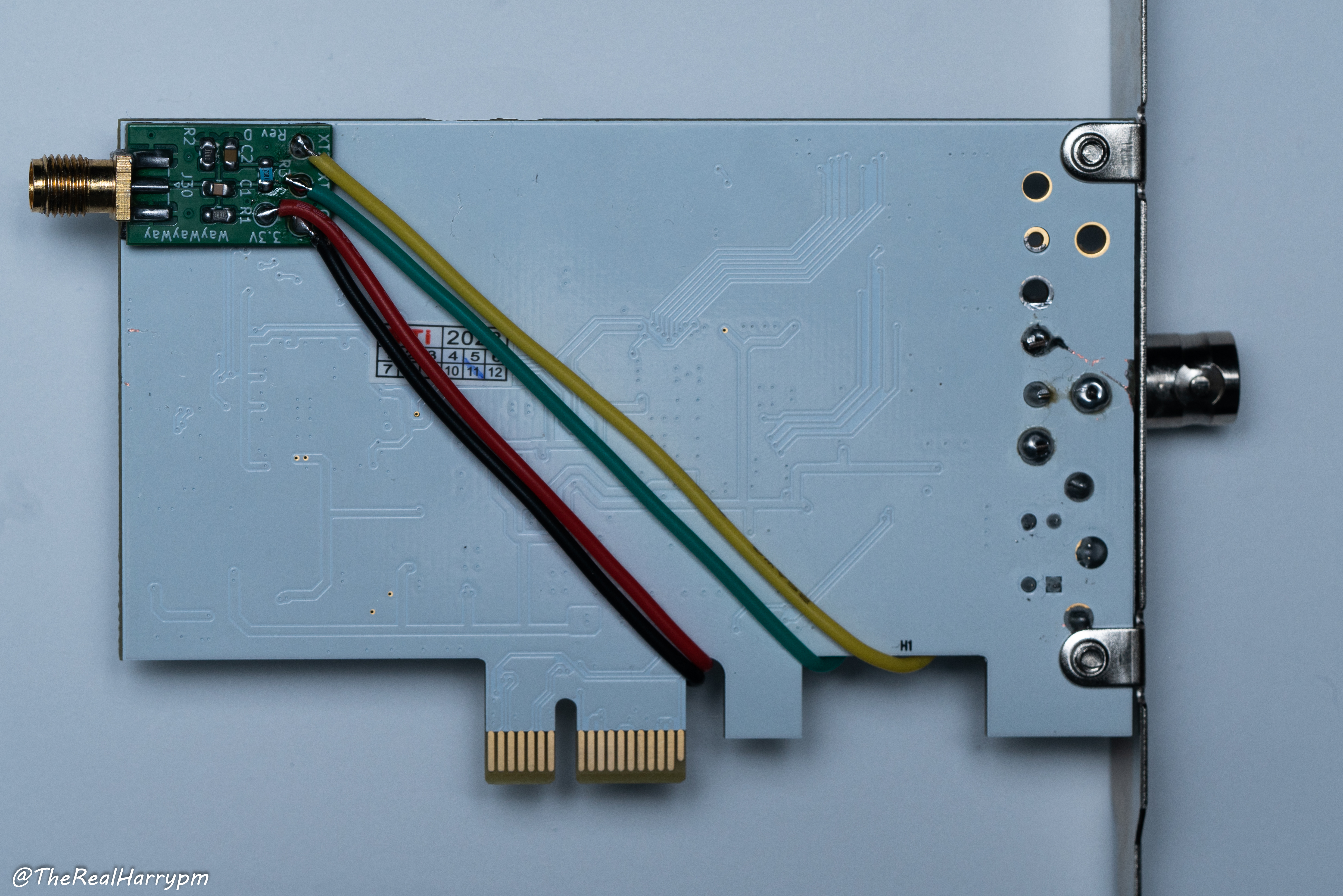
Warning
Ensure all parts are populated in the correct orientation as shown in the image below.
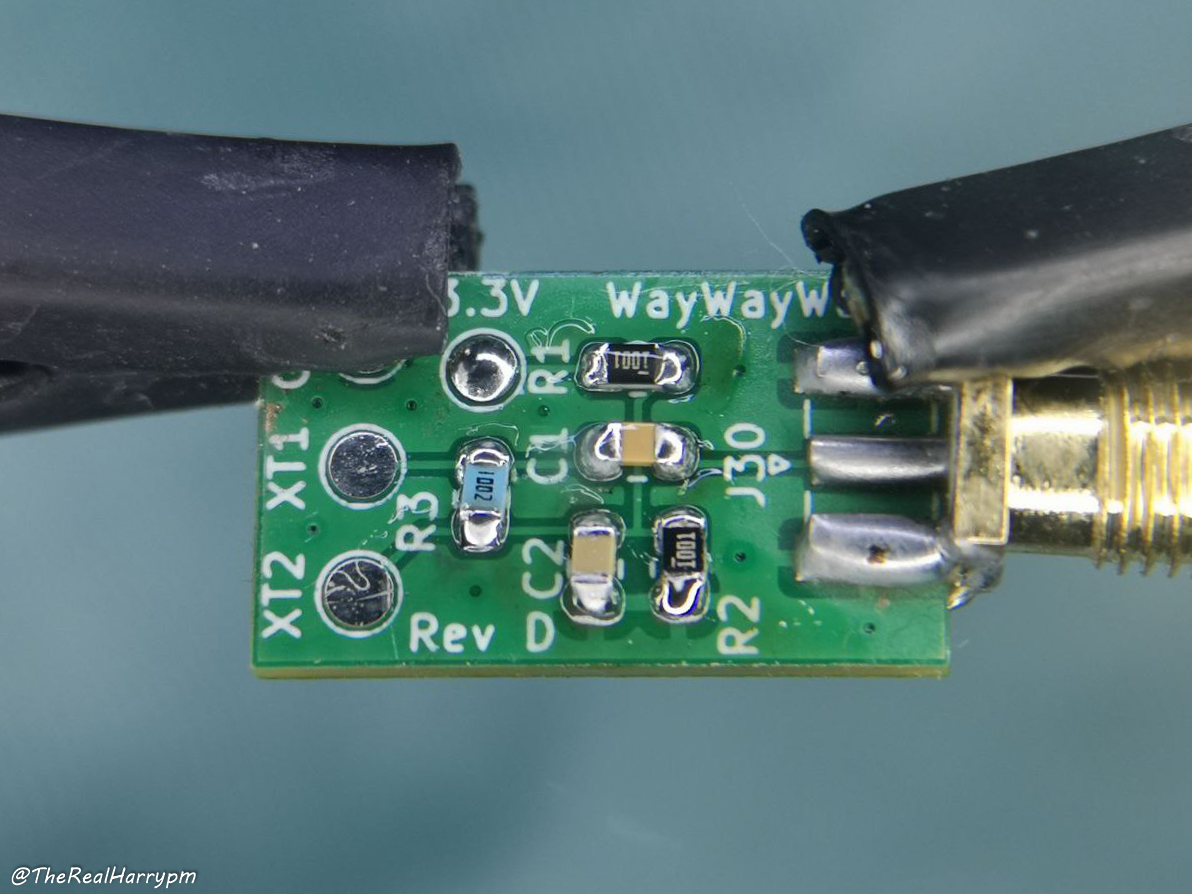
- J30: SMA Edge Mount
- C1: 1.5 nF (6V or greater, ceramic X5R or X7R)
- C2: 10 nF (6V or greater, ceramic X5R or X7R)
- R1: 1K Ohm (5% tolerance or better)
- R2: 1K Ohm (5% tolerance or better)
- R3: 10K Ohm (5% tolerance or better)
- 2mm thick 25mm wide double sided foam tape.
- 26AGW wire in 4 colours, works well and is very available.
Warning
Always check via line indicator on SMD ports the polarity of diodes are in-line with indicator on PCB
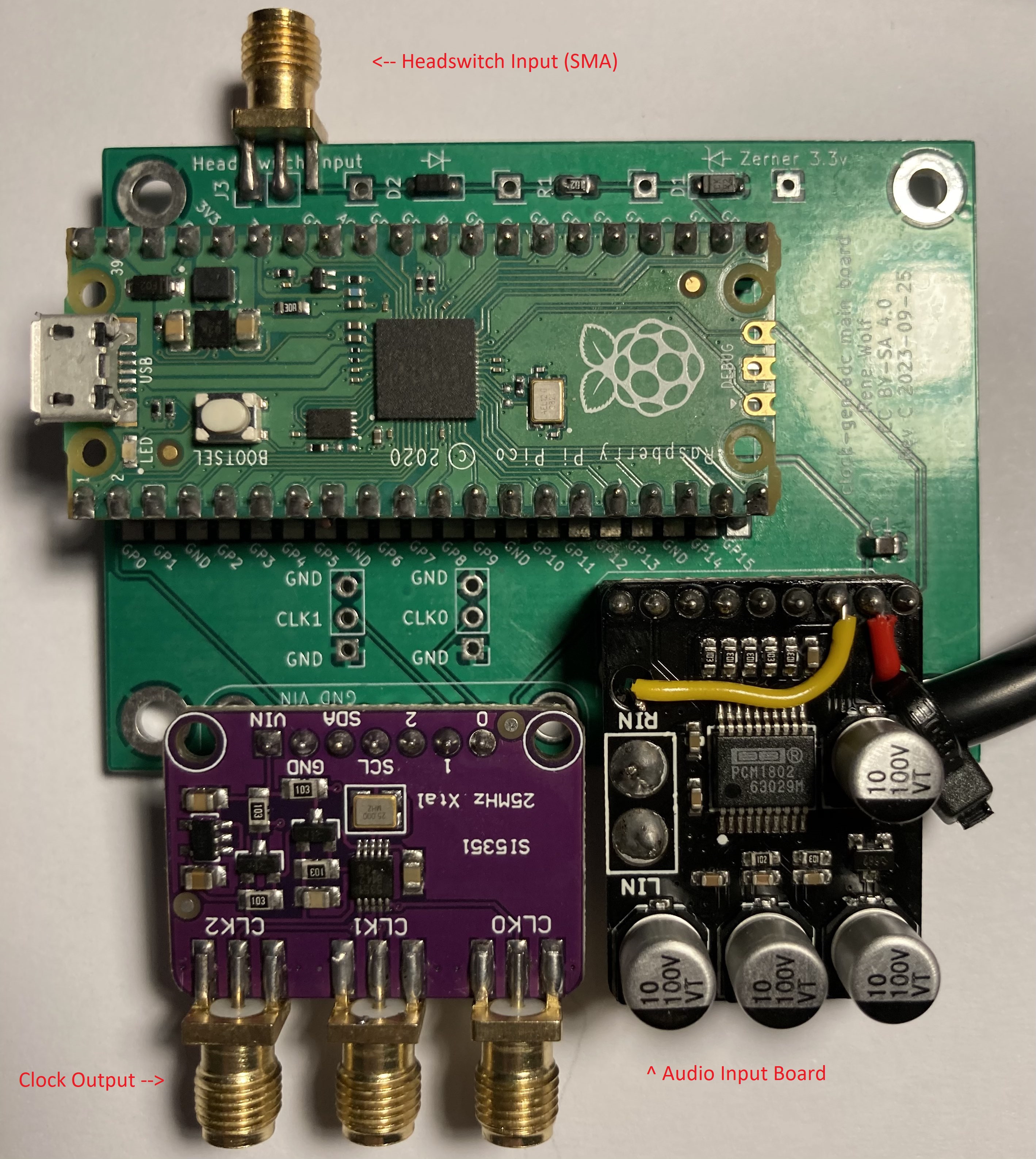
There is 3 off shelf boards used for this:
AliExpress is most likely the cheapest place to source these but are very available on Amazon and other venders globally.
-
Raspberry Pi Pico as the interface and control board via USB (you can use the stock one or USB-C ones)
-
Adafruit Si5351A for generating the shared clock source with 5 potential inputs.
-
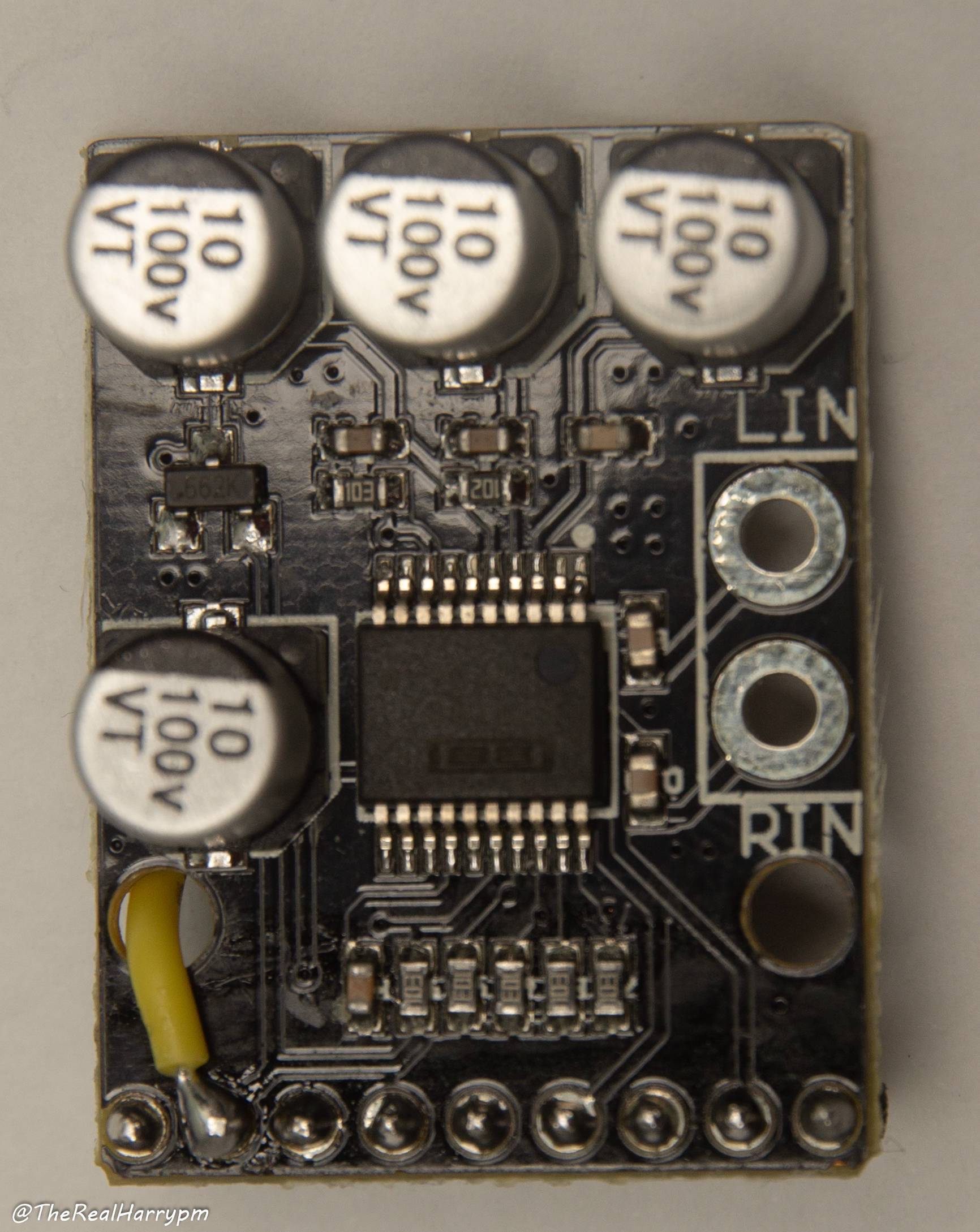
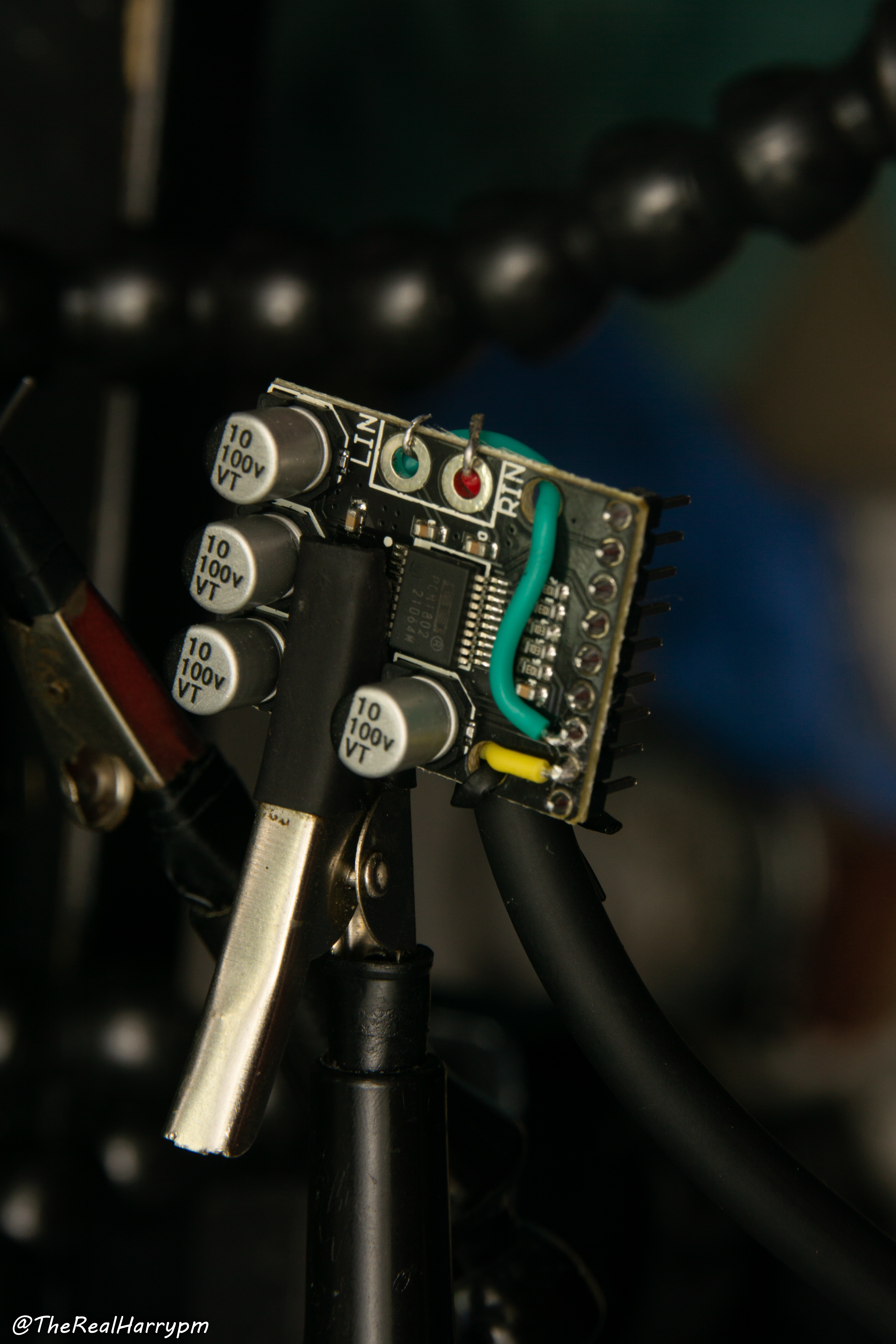
PCM1802 ADC for L/R input Linear/HiFi audio capture.
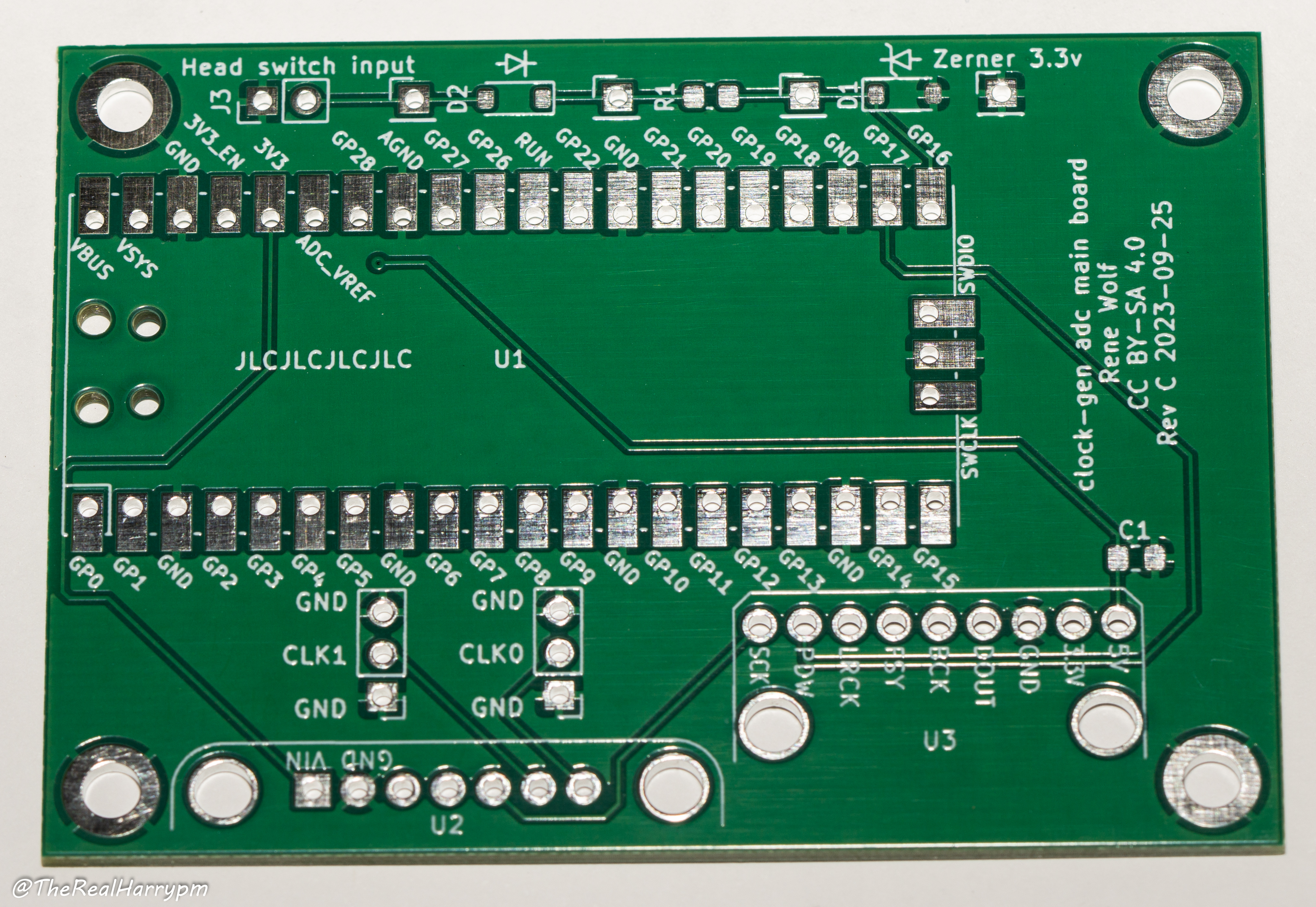
Parts:
- SMA Edge Mount (On Headswitch/Ground Pads)
- C1: 10 µF
- R1: 1K Ohm
- D1: 3.3V zener diode
- D2: Generic switching diode
Sockets:
Header Socket Pin Size: 2.54mm
- U1: 2x 20-pin Header Socket (Pi Pico)
- U2: 1x 9-pin Header Socket (PCM1802)
- U3: 1x 7-pin Header Socket (Si5351A)
Board Parts:
- 1x Audio Cable (A 1m XLR cable is ideal as its shielded)
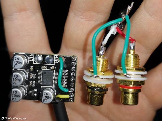
- 1x Pair of RCA or TRS audio connectors.
- 1x Small Zip-Tie or Cable-Tie (to secure audio line)
Interface:
- USB 2.0 Internal to Type-A or to Micro-B (or USB-C) cable
Note
The Si5351A kit headers are not recommended for socketed connectors, its recommended to solder headers then the board to said 2.54mm headers directly to ensure a secure connection.
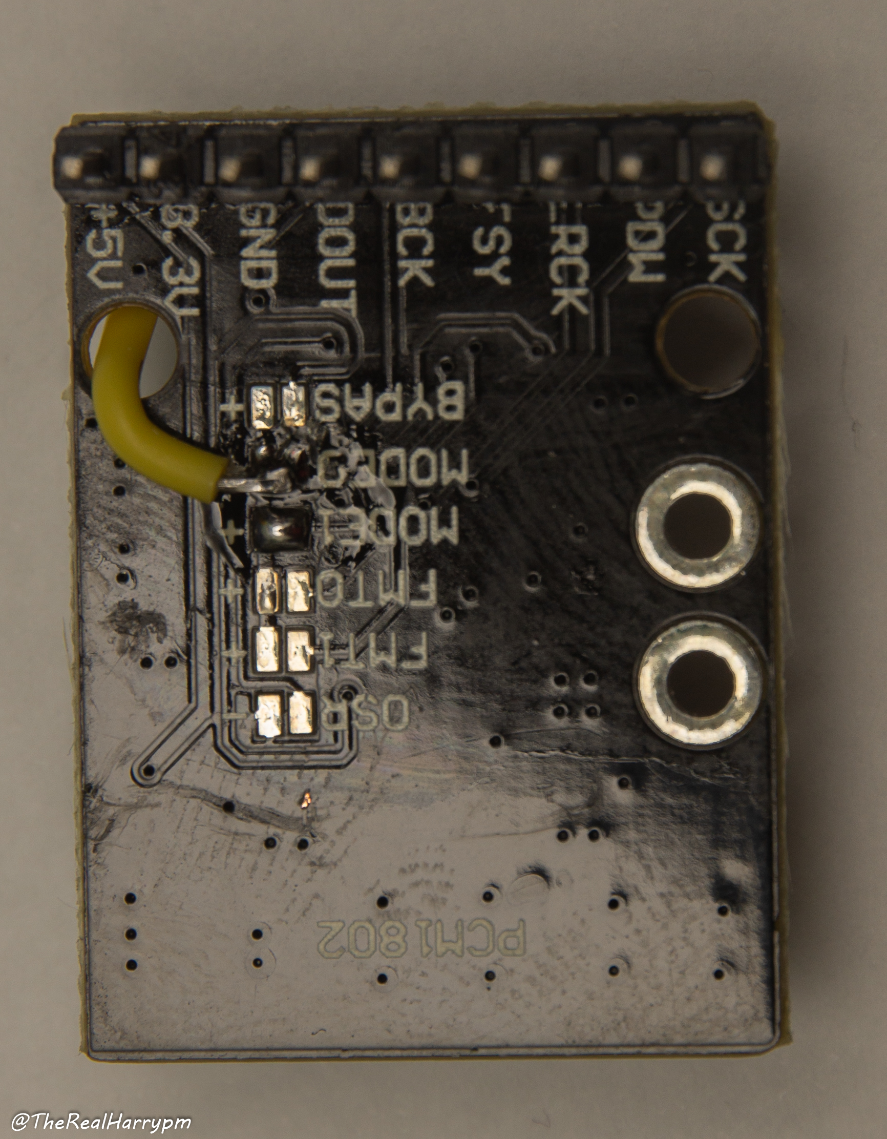
Note
The PCM1802 Board requires a boge wire bypass mod in most cases if 3.3v lines are not connected, its always good to test with a multi-meater if possible.
Parts
- PCM1802 Board
- 8Pin 2.54mm Headder
MODE0 with 3.3v Bridge Mod
Grounding
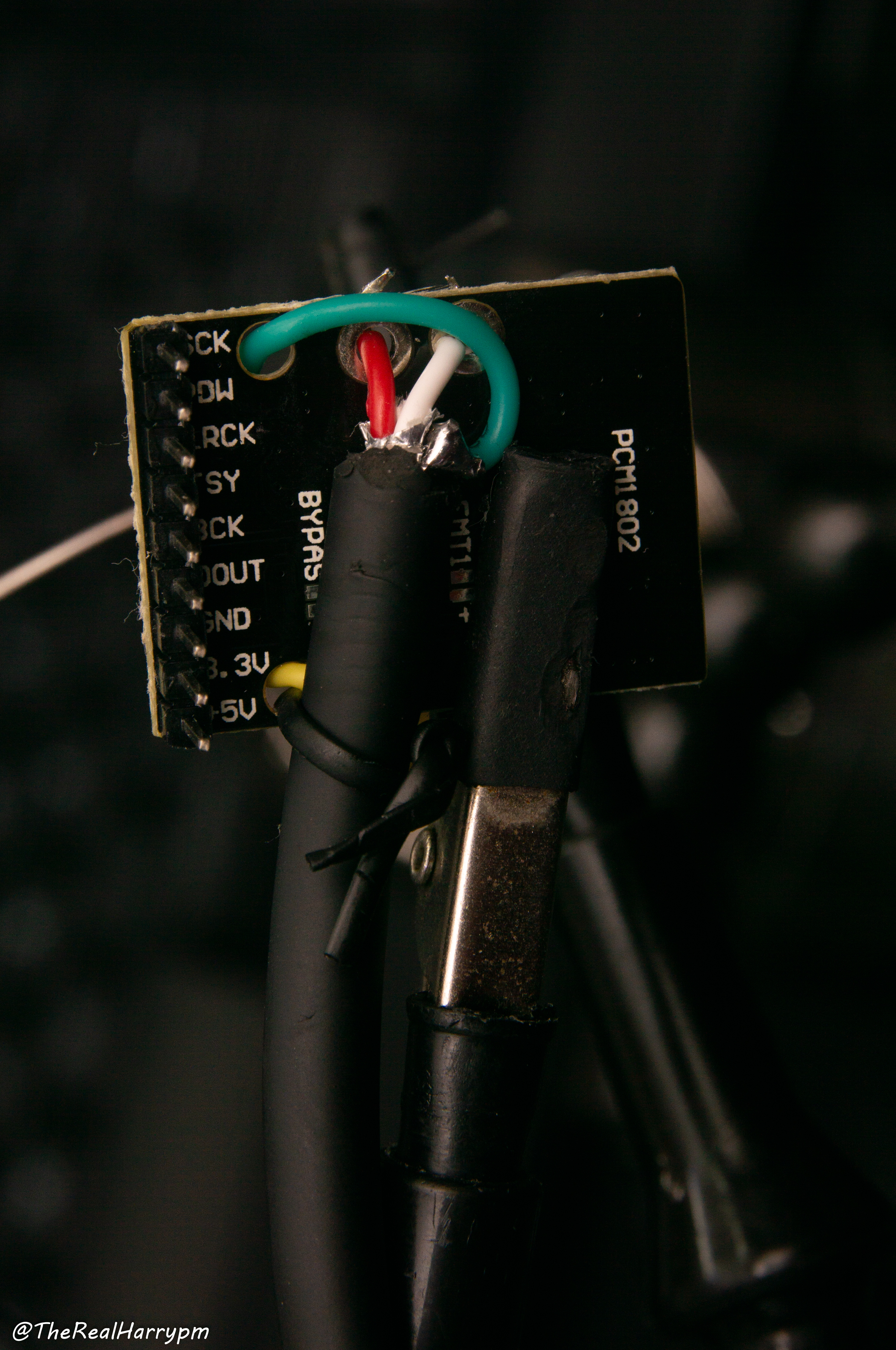
Finished Board (RCA as example)
L 40mm X W 40mm X H 11mm heatsinks are readily available.
Previous Page CX Cards
Sub-Page RF Capture Guide
Next Page Hardware Installation Guide
- FAQ - Frequently Asked Questions
- Diagram Breakdowns
- Visual-Comparisons
- VCR Reports / RF Tap Examples
- Download & Contribute Data
- Speed Testing
- Visual VBI Data Guide
- Closed Captioning
- Teletext
- WSS Wide - Screen Signalling
- VITC Timecode
- VITS Signals
- XDS Data (PBS)
- Video ID IEC 61880
- Vapoursynth TBC Median Stacking Guide
- Ruxpin-Decode & TV Teddy Tapes
- Tony's GNU Radio For Dummies Guide
- Tony's GNU Radio Scripts
- DomesDay Duplicator Utilities
- ld-decode Utilities