GunnsFluidCondensingHxSeparator - nasa/gunns GitHub Wiki
This extends GunnsFluidConductor with a model of the type of condensing heat exchanger typically used in a micro-gravity environment. The model consists of three main components:
- Condensing HX: This functions like a GunnsFluidHeatExchanger and interfaces with the thermal aspect in the same way. Additionally it calculates condensation rate based on water vapor concentration in the air stream, temperatures of the air and HX walls, and flow rates. Condensed water is removed from the air stream and pooled on the HX fins.
- Slurper: Condensation on the HX fins flows towards a slurper bar at the back of the HX and gets pulled inside by suction from the separator pump. The slurper carries this liquid/ air mixture into the separator itself. This models the transfer rate of the liquid from the HX to the separator as a function of pooled mass on the HX fins and the amount of suction from the separator (proportional to separator spin speed).
- Separator: This is a spinning drum that collects the liquid condensate towards the outside of the drum. The liquid is is pressurized by the centrifugal effect of the spinning and pumped into a water bus, whereas the air gas escapes through a gas impeller and is returned to the air stream. This model works in conjunction with a GunnsFluidSeparatorLiquid link in the same or an external network. This link sends the liquid pumped pressure & temperature of the condensate to the liquid bus link and receives a liquid transfer demand mass flow rate. The transferred liquid mass is removed from the drum. The separator can interface with a dynamic motor model just like a GunnsGasFan link.
This model doesn't track the air pulled through the slurper bar and separator, since it is always returned to the main air stream. Thus, to the network this link appears as a single air flow path between two nodes, from which some water vapor is removed.
This model can only condense water vapor (GUNNS_H2O fluid constituent).
Liquid water doesn't exist as a GUNNS fluid in this link; rather the liquid mass is tracked internally in the model. This link models evaporation of the liquid in the HX and separator when the system is drying out. Evaporated water is added to the air stream.
Unlike most other pipe & HX links, this link does not model isentropic expansion. This link can remove and add water vapor from/to the gas stream passing through it.
The following diagram shows how this link can interface with other GUNNS links, for best results: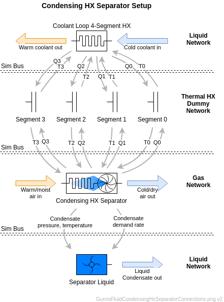
Port Connection Rules (These are limitations on the port connection to nodes that the link enforces in run-time):
- Same as GunnsFluidConductor.
Other Rules (These are extra rules you should always try to follow):
- Both nodes must be gas phase.
- Water vapor (GUNNS_H2O) must be a fluid constituent in the network.
- As with normal conductors, try to combine conductors and this link in series into a single GunnsFluidCondensingHxSeparator whenever possible to reduce network node count.
Configuration Data Parameters:
- maxConductivity: Same as GunnsFluidConductor.
- The following terms configure the Heat Exchanger portion of the model:
- hxNumSegments: Same as numSegs in GunnsFluidHeatExchanger.
- hxDryHtc: Same as heatTransferCoefficient in GunnsFluidHeatExchanger. This is the dry fin heat transfer coefficient of the heat exchanger. This gets divided equally among all segments - segments cannot have their own coefficient.
-
hxWetHtcFactor (default = 0 1/kg): This is the contribution of condensate
mass in the HX to the overall HX heat transfer coefficient. This can model the effect
that wetted surface area on the HX fins has on overall heat transfer, as opposed to
a purely dry area. This term can be set to zero if the effect is not desired.
The total heat transfer coefficient of the HX is calculated as:
UA_total = hxDryHtc * (1 + hxWetHtcFactor * HX_condensate_mass).
- hxWetFlowFactor (default = 0 1/kg, must >= 0): This is the effect the pooled condensate on the HX fins has on the air flow rate through the HX. In general there is a slight reduction in air flow the more condensate is pooled on the HX fins. This value is in percent flow reduction per kilogram of condensate mass, so a value of 1.0 will completely block the air flow at 1.0 kilogram of pooled condensate. This term can be set to zero if the effect is not desired.
- hxEvaporationCoeff (default = 0 kg/s/kPa, must >= 0): This controls the evaporation rate of water from the pooled condensate on the HX fins. Higher values cause more rapid evaporation. The rate is proportional to the difference in the water vapor pressure and concentration of water vapor in the air stream, so dryer & hotter air causes more rapid evaporation.
- The following terms configure the Slurper portion of the model:
- slurperFlowMassDry (default = 0 kg, must >= DBL_EPSILON): This is the mass of liquid pooled on the HX fins before it will begin flowing through the slurper and into the separator, from an initially dry state.
- slurperFlowMassWet (default = 0 kg, must >= DBL_EPSILON): This is the mass of liquid pooled on the HX fins before it will begin flowing through the slurper and into the separator, from an initially wetted state.
- slurperFlowRateRef (default = 0 kg/s, must >= DBL_EPSILON): This defines the rate at which the condensate flows from the HX to the separator via the slurper, at the wsReferenceSpeed. Actual flow rate varies with the separator spin speed, and is typically faster than the rate of condensation on the HX fins. Thus once this flow starts, it can drain the HX liquid faster than new condensate is being formed, and eventually the pooled mass on the fins reaches zero, and flow pauses. Typically it takes longer for flow to first begin when the HX is completely dried out (defined by slurperFlowMassDry), and subsequent pauses are shorter when the HX has been condensing ("wetted" -- slurperFlowMassWet). You can configure the above terms to control the relative length of flowing & paused cycles.
- The following terms configure the Separator portion of the model:
-
wsMassExponent (default = 0, must be (0.1 - 10): The pumped pressure of
the water in the spinning separator drum is exponently proportional to the pooled mass
by this exponent value. First, a constant
power curve coefficient Kp is initialized from these configuration parameters as:
Kp = wsReferencePressure / wsReferenceSpeed / (wsMaxCondensate ^ wsMassExponent).
Then, the pumped delta-pressure dp of the liquid is calculated during run-time as a function of the above constant, and current drum spin speed and pooled mass as:dp = Kp * spin_speed * (pooled_mass ^ wsMassExponent).
This gives you flexibility in controlling how rapidly the pumped pressure rises as condensate flows in from the slurper, etc. - wsMaxCondensate (default = 0 kg, must >= FLT_EPSILON): This is the maximum mass of pooled water the drum can contain before the water floods into the air outlet. When this happens, the model outputs a "liquid overflow" flag for sensors and controllers to respond to, etc.
- wsReferenceSpeed (default = 0 rev/min, must >= FLT_EPSILON): This defines the reference drum spin speed for the equations detailed above.
- wsReferencePressure (default = 0 kPa, must >= FLT_EPSILON): This defines the reference pumped delta-pressure for the equations detailed above.
-
wsReferenceTorque (default = 0, must <= 0): This defines the shaft torque
the model will output to a dynamic motor model at the wsReferenceSpeed. This
simplified model of shaft torque is proportional to current spin speed as:
torque = wsReferenceTorque * spin_speed / wsReferenceSpeed.
- wsDriveRatio (default = 0, must >= 0): Same as driveRatio in GunnsGasFan.
- wsEvaporationCoeff (default = 0 kg/s/kPa, must >= 0): Similar to hxEvaporationCoeff, except this pertains to the pooled water in the separator drum.
-
wsMassExponent (default = 0, must be (0.1 - 10): The pumped pressure of
the water in the spinning separator drum is exponently proportional to the pooled mass
by this exponent value. First, a constant
power curve coefficient Kp is initialized from these configuration parameters as:
Input Data Parameters:
- malfBlockageFlag: Same as GunnsFluidConductor. This malfunction blocks the main air flow path through the HX. It does not affect condensate flow through the slurper or pumped from the separator.
- malfBlockageValue: Same as GunnsFluidConductor.
- wallTemperature: Same as initialSegmentTemperature in GunnsFluidHeatExchanger.
- wsMotorSpeed: Same as motorSpeed in GunnsGasFan, this is the initial motor shaft speed for the water separator.
- wsCondensateMass (default = 0 kg, must >= 0): This is the initial pooled liquid mass in the water separator.
- hxCondensateMass (default = 0 kg, must >= 0): This is the initial pooled liquid mass in the heat exchanger.
- transferFlowRate (default = 0 kg/s): This is the initial flow rate of liquid being pumped out of the separator. Values are positive for water leaving the separator.
- slurperState (default = GunnsFluidCondensingHxSeparator::PAUSED_DRY): This is the initial flowing state of the slurper. When set to FLOWING, the sluper is actively flowing at the start of the run. When in PAUSED_DRY, the HX must pool slurperFlowMassDry mass of condensate before the sluper will resume flowing. Similarly, PAUSED_WET must pool slurperFlowMassWet mass before flow will resume.
- Health & Status Warning: limited segment temperature to valid range: This message indicates that the HX segment has a wall temperature that is out of range. Since the segment temperature usually comes from a thermal aspect, this will usually be due to the coolant loop being too hot or too cold, due to tuning or heat balance issues. Most often this will occur at the lower temperature range, as condensing heat exchangers try to get as close to the freezing point of water as possible without actually freezing, to condense the most water. The valid range is (273.15-572.999) K to avoid this message.
- N/A