GunnsGasFan - nasa/gunns GitHub Wiki

This extends GunnsFluidPotential with a model of a fluid impeller. This can be used to model all types of axial, radial, or mixed-flow ducted fans and centrifugal (constant-head) pumps. This is mainly used for gas impellers, but it can also be used for liquid centrifugal pumps if liquid cavitation is not desired. If cavitation is desired, use the GunnsLiquidCentrifugalPump instead. (We recommend that you do use cavitation for liquids). This link should not be used for positive displacement (constant-volume) pumps such as pistons, etc. For those types of pumps, use the GunnsGasDisplacementPump link instead.
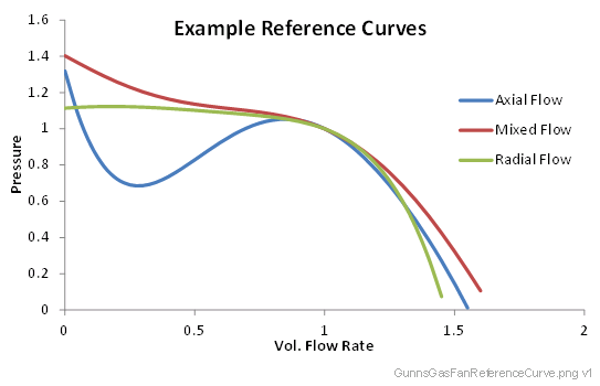
This link implements the fan performance curve for produced pressure (kPa) as a function of volumetric flow rate (m3/s), rotational speed (rev/min), and inlet density (kg/m3). The performance curve for fans is typically documented (sometimes called a P-Q curve in literature), and our curve is up to a 5th-order polynomial fit to it. Effects of spin speed and density are governed by the fan Affinity Laws. Users can supple their own performance curve, or the model can calculate one based on a best efficiency point.
This link is designed to interface with a motor model. The motor supplies a shaft rotational speed to the fan, and the fan returns a shaft torque to the motor. The shaft torque is due to the useful work applied to the fluid as well as hydraulic losses. Hydraulic losses use a generalized model for shaft power as a function of impeller specific speeds between 0.2 - 5 radians, which covers most radial, mixed and axial flow pumps.
This link models isentropic expansion and convection heat transfer between the fluid and the fan/pipe wall, similar to other pipe & HX links. This link does not modify the mixture of the fluid passing through it.
This link has the same connection rules as GunnsFluidPotential. Apart from the turbine effect, which is not modeled, multiple fans can be staged in any combination, either in parallel or series, and in sympathetic or opposing directions and interact in a realistic manner.
Port Connection Rules (These are limitations on the port connection to nodes that the link enforces in run-time):
- Same as GunnsFluidConductor.
Other Rules (These are extra rules you should always try to follow):
- Do not mix fluid phases across the link. That is, both nodes should contain the same phase (gas or liquid), and not different phases.
- As with normal conductors, try to combine conductors and GunnsGasFans in series into a single GunnsGasFan whenever possible to reduce network node count.
- The network solver has a configuration parameter called minLinearizationP which can interfere with the performance of these fan links if has too high a value. Always set this parameter to less than 5% of the lowest pressure rise that any of the fans in your network are expected to operate at. In other words, with all fans spinning at their lowest commandable speeds, and with all plumbing that they flow through as wide-open as possible, the lowest delta-pressure any of the fans creates.
- As with check-valves, it is a good idea to add some volume to the fan's downstream node. This promotes model stability.
- Always finish tuning this link and the system that it flows through before you attempt to hook up and tune a motor model.
Configuration Data Parameters:
- maxConductivity: Same as GunnsFluidPotential.
- expansionScaleFactor: Same as GunnsFluidConductor.
- The following "reference" terms define the fan performance curve at the reference speed and inlet density. This is up to a 5th-order polynomial defining fan pressure rise (kPa) as a function of true volumetric flow rate (m3/s). There are some requirements this curve must satisfy:
- At volumetric flow rate = 0, the curve must give pressure > 0.
- The pressure curve must cross from positive to negative at some volumetric flow rate between 0 - 1000 m3/s.
- Coefficients 1-5 are optional, provided the above requirements are met. Additionally, you
can have the fan model calculate it's own performance curve by setting coefficients 1-5 all
to zero, and coefficent 0 to the pressure rise at the Best Efficiency Point (BEP). When using
this configuration, the other BEP terms should also be defined (see below). Your GUNNS
repository contains a gunns/aspects/fluid/tuning/Gunns_Pump_Fan_Tuning_Helper.xlsx
spreadsheet that is mainly useful for tuning a motor model in conjunction with this fan link,
but its "Impeller Curve" sheet has some tools for helping to generate your fan performance
curve.
- referenceDensity (default = 0 kg/m3, must be > 0): This is the fluid inlet density for the reference performance curve.
- referenceSpeed (default = 0 rev/min, must be > 0): This is the impeller rotational speed for the reference performance curve.
- referenceCoeff0 (default = 0 kPa, must be > 0): This is the 0th-order polynomial coefficient for the reference performance curve. It also defines the reference dead-head pressure of the fan, which is the standing pressure rise the fan creates when there is zero flow. If all other coefficients are zero, this term defines the pressure rise at the BEP, and is used to estimate the rest of the reference coefficients.
- referenceCoeff1 (default = 0): This is the 1st-order polynomial coefficient for the reference performance curve.
- referenceCoeff2 (default = 0): This is the 2nd-order polynomial coefficient for the reference performance curve.
- referenceCoeff3 (default = 0): This is the 3rd-order polynomial coefficient for the reference performance curve.
- referenceCoeff4 (default = 0): This is the 4th-order polynomial coefficient for the reference performance curve.
- referenceCoeff5 (default = 0): This is the 5th-order polynomial coefficient for the reference performance curve.
- The following Best Efficiency Point (BEP) terms are optional. The efficieny and QBep govern the model of shaft power and torque for integration with an optional motor model. When not used (either term = zero), the impeller is assumed 100% efficient at all speeds, and only the "useful hydraulic" power to move the fluid downstream is modeled, as shown in the example charts below. When both are used, the modeled torque & power include more realistic affects such as hydraulic losses, bearing & seal friction, etc (the "total impeller" line in the example charts below). These terms should also be defined if you are relying on the model to generate a reference performance curve.
- bestEfficiency (default = 0, must be (0-1)): This is the total efficiency of the impeller at the Best Efficiency Point of the reference performance curve. The total efficiency is the ratio of the useful hydraulic to total impeller power, as shown in the example charts above. Real impellers typically have between 0.5 - 0.85 best efficiency.
- referenceQBep (default = 0 m3/s): This defines the volumetric flow rate of the Best Efficiency Point on the reference curve. It should be somewhere between zero and the maximum flow rate (where pressure crosses zero). Real impellers typically have BEP around 60-70% maximum flow rate.
- filterGain (default 0.5, recommend between (0.1-0.5)): This is the gain for a stability filter in the fan model. The default value of 0.5 usually suffices, but lower values can sometimes improve stability if needed (see below).
- driveRatio (default 1.0, must be > 0): This is the gear ratio of motor shaft to impeller speed.
- thermalLength: Same as GunnsFluidValve.
- thermalDiameter: Same as GunnsFluidValve.
- surfaceRoughness: Same as GunnsFluidValve.
- checkValveActive: (default false): This flag can be used to activate a built in check valve feature. This is a simplified check valve, with binary open/close positions, and assumes open pressure = close pressure = 0.0 (basically, fully open for positive flow, fully closed for negative flow)
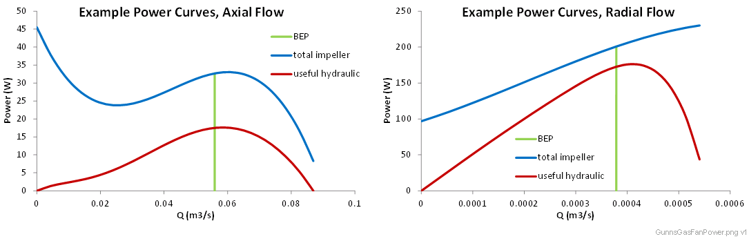
- The "useful hydraulic" curve comes directly from the reference performance
curve and the equation relating useful hydraulic power P to volumetric flow
rate Q and pressure rise dp:
- The "total impeller" power curve is a generalized function of impeller
specific speed, which the model automatically determines for you. The above example charts
show an axial fan with specific speed = 3.2 radians, and the radial example is for a specific
speed = 0.4 radians.
Input Data Parameters:
- malfBlockageFlag: Same as GunnsFluidConductor.
- malfBlockageValue: Same as GunnsFluidConductor.
- sourcePressure: Same as GunnsFluidPotential.
- motorSpeed (default = 0 rev/min, must be >= 0): This is the initial motor shaft speed.
- wallTemperature: Same as GunnsFluidValve.
- Pressure/flow instability: The pressure and flow created by this link should normally be smooth if it is tuned properly. Rapid and chaotic oscillation in these parameters are usually caused by poor tuning. Here are some guidelines to follow to avoid or fix this problem.
- Tune the system for reasonable flow rates. Real fans normally operate at flow rates at or slightly above their Best Efficiency Point. This is a function of the duct that the fan is flowing through. If the duct has too much conductivity, the fan will operate at close to the maximum flow rate on its performance curve, and this can sometimes cause instability in the model. Similarly, blocking the duct too much can drop the flow rate of axial fans into their stall region (the dip to the left of the BEP on their performance curve) and this can cause erratic fan pressure as it searches for equilibrium with the system (this is real-world behavior).
- Make sure the network solver's minLinearizationP configuration parameter is less than 5% of the fans lowest expected operating delta-pressure.
- If the fan is connected to a dynamic motor model, there is a feedback loop between the motor speed and the fan torque, which can be unstable if not tuned properly. This involves motor model tuning which is not covered here; common problems include an unrealistically powerful motor, too-low inertia, bad filter gains in the motor controller, or excessive data lag between the models.
- Sharp corners and steeply sloped regions of the fan's performance curve degrade stability. The vast majority of real impellers will have a performance curve that looks something like the examples above. If your curve has very steep areas and sharp corners, it is probably not a good curve fit to the fan you are modeling. Using a shallower and smoother curve can help.
- The fan's filterGain value can be lowered to promote stability if needed. This can fix some stability problems. This is particularly useful in cases with multiple fans affecting each other. Don't use too low of a value, such as below 0.1, as this can cause the fan model to become very sluggish and result in large long- period oscillations in flow & pressure.
- Health & Status Warning: failed to find the impeller-system intersection: Occasional warnings during large transients in the network are not a problem. Consistently repeated warnings indicate a serious problem with the fan setup. This is usually caused by a poorly-conditioned fan performance curve, or something that can be avoided by following the guidelines listed above.
-
Negative Inlet Pressure: The generic re-usability of the GUNNS solver allows for
negative node potentials - in the case of fluid networks, pressure. Obviously negative pressures
aren't possible in the real-world, so we desire to set up fluid networks such that they
don't produce negative pressure values. The GunnsGasFan is one link that can do so if it is
improperly tuned. The fan can pull a suction on the inlet node relative to the rest of the
system if the flow path conductivities leading to the inlet are very small. If the fan's
dead-head pressure is large enough, this can pull the inlet pressure down below zero.
Radial-flow fans & pumps typically can create large enough pressures that this can be a
concern. Take these precautions to avoid this problem:
- Have some volume on the fan's exit node.
- Use a realistic reference curve at realistic inlet fluid density -- then even completely choking off the fan inlet cannot pull the inlet pressure below zero.
- Liquid systems always have some way to pressurize the liquid at the pump inlet to avoid cavitation. This is often used with an accumulator or flexible lines, etc. Always include such a link near the pump inlet and do not isolate the pump from it.
- Parallel fans "shut off": In some cases when two or more fans are directly in parallel and running at the same time, one of the fans will stop producing pressure and the other fan will take over. Although the net effect on flow through the system is largely unaffected, this can cause incorrect power signatures in the fan's motor models because one fan is doing all the work. This is a current limitation of the model.
- N/A