GunnsFluidHeatExchanger - nasa/gunns GitHub Wiki

This link extends GunnsFluidConductor with convective heat flux between the pipe wall and the fluid passing through it. This heat transfer is computed for multiple segments along the length of the flow, each with its own wall temperature and heat transfer coefficient. The exit of one segment leads into the next segment, and so on. The number of segments is configurable.
The link does not modify the mixture of the fluid passing through it. Also note that this HX does not model condensation or the assocated extra heat of phase change. This is particularly important for air heat exchangers - this link will not model condensation of water vapor through a cold HX. For heat exchangers where condensation needs to be modeled, use the GunnsFluidCondensingHxSeparator instead.
The GunnsFluidHeatExchanger can be hooked up to nodes in exactly the same ways that regular fluid conductors can. We use this link for most heat exchangers and coldplates in a vehicle sim. The most typical uses of it are shown below:
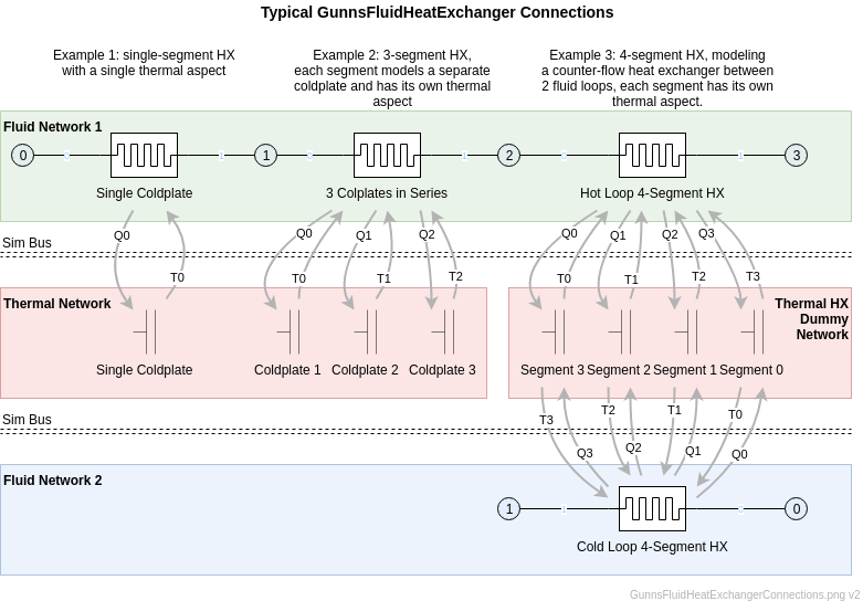
Each segment in a HX link typically has its own thermal aspect in a thermal network. Each fluid segment sends the convection heat flux to the thermal aspect (the "Q" sim bus data shown above), and receives a wall temperature from the thermal aspect (the "T" data). In these examples we label the individual segment's data being transferred as Q0, Q1, etc.
- Example 1, in which a HX link with a single segment interfaces with its thermal aspect, is identical in function to the thermal convection done in other links such as valves, fans, etc.
- In Example 2, we configure the HX link with 3 segments to represent 3 separate coldplates in series. The temperature of each coldplate is owned by a separate thermal aspect. We could model each coldplate with its own single-segment HX link, like in Example 1. However, using a single HX link with multiple segments to represent multiple coldplates in series reduces the number of nodes in the fluid network, which can save a lot of CPU time. This also illustrates how individual segments of the HX link can interface with their own thermal aspects.
- Example 3 shows a good way to implement heat exchangers between multiple fluid loops. The number of segments (numSegs below) is configured as needed for the correct HX performance (more on that below), and each segment interfaces with its own thermal aspect. Most real-world heat exchangers are counter-flow or cross-flow, meaning the hot and cold fluid paths flow through the box in opposite directions, for maximum efficiency. We achieve similar results by cross-wiring the simbus interfaces between the two fluid links, as shown. Cold loop segment 0 interfaces with Hot loop segment 3, and so on. This counter-flow in the sim is necessary to achieve high enough efficiency, just as it is in real-world.
This shows some less typical applications of the fluid heat exchanger:
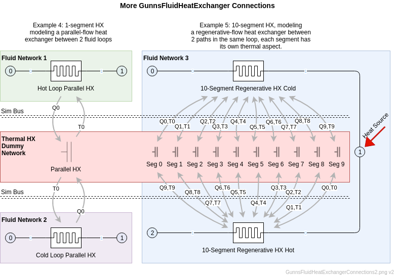
- Example 4 is very similar to Example 3 except a parallel-flow HX is modeled instead of a counter-flow HX. A parallel-flow HX only ever needs one segment (discussed below).
- Example 5 shows a counter-flow regenerative HX, in which the same fluid is both heated and cooled by itself through two opposing passes through the HX, with some process in between. This is typically used to efficiently heat the fluid up to perform some chemical reaction on it, then cool the products back down again. Such a setup usually requires 10 segments or more (discussed below).
Port Connection Rules (These are limitations on the port connection to nodes that the link enforces in run-time):
- Ports 0 and 1 cannot connect to the same non-Ground node.
Other Rules (These are extra rules you should always try to follow):
- Same as GunnsFluidConductor.
- Use the implementation from Examples 2 or 3 above for multiple heat-exchanging objects in series to reduce network node count.
- Use as few segments as you can and still achieve the desired results. An excess number of segments to model a HX uses up more memory but gives no additional fidelity.
- For heat exchanger models only (fluid-thermal-fluid heat exchangers as shown in Examples 3-5, not coldplates), use a separate thermal network just for their HX segment thermal aspects. Configure this network's solver to run in DUMMY mode. In DUMMY mode, nodes have no conductivities between them, each thermal capacitor updates its own temperature, and the GUNNS solver doesn't have to solve anything. This removes the CPU penalty for number of nodes and saves a large amount of CPU time. Then, since the network doesn't use significant CPU, update it at the same execution rate as the fluid networks for extra stability.
Configuration Data Parameters:
- maxConductivity: Same as GunnsFluidConductor.
- expansionScaleFactor: Same as GunnsFluidConductor. Note that this isentropic expansion happens before the convection heat transfer is calculated, and the inlet temperature to the heat convection is already chilled by this effect.
-
numSegs (default = 0, must be > 0): This is the number of segments used in this
heat exchanger link. As described in Example 2 above, segments can be used to model
individual heat-exchanging objects in series (such as coldplates). In Example 3, multiple
segments are used to simulate a single fluid-fluid heat exchanger device. In this case, the number
of segments needed depends on the maximum efficiency of the heat exchanger and the thermal
capacities of the fluid loops at that point. This differs for counter-flow and parallel-flow
setups:
-
Counter-flow: The vast majority of real heat exhangers are counter- or cross-flow
because this arrangement is much more efficient than parallel-flow.
The maximum possible efficiency of a counter-flow HX is 100%, given unlimited segments
and heat transfer coefficient.
The following equation provides a rough prediction of how many segments will be needed
to achieve a desired efficiency:
numSegs (round up) = (TC_hot / TC_cold) / (1 - efficiency),
where TC_hot and TC_cold are the thermal capacities (W/K) of the hot and cold fluid paths, respectively, and efficiency is fractional (0-1). Fluid thermal capacity is mass flow rate (kg/s) times fluid specific heat (J/kg/K). Efficiency (also called "hot-side effectiveness" in literature) is defined as the ratio of temperature drop of the hot loop to the difference in hot and cold inlet temperatures.
Conversely, the maximum possible efficiency (at infinite heat transfer coefficient) of a HX link with numSegs is:
max_efficiency = 1 - (TC_hot / TC_cold) / numSegs.As an example, a typical hot loop/cold loop counter-flow heat exchanger in space vehicles has about 1:3 hot/cold thermal capacity ratio, and 90% efficiency. To achieve this we need (1/3) / (1 - 0.9) = 4 segments, and our maximum possible efficiency would then be 1 - (1/3) / 4 = 92%.
As another example, a regenerative heat exchanger always has a near-1:1 thermal capacity ratio, so to achieve 90% efficiency it needs (1) / (1 - 0.9) = 10 segments.
-
Parallel-flow: In this case, always configure numSegs = 1.
The maximum possible efficiency of a parallel-flow HX,
given unlimited heat transfer coefficient, is limited to:
max_efficiency = 1 / ((TC_hot / TC_cold) + 1).
As an example considering the typical hot/cold ratio of 1:3 in a parallel setup, the maximum theoretical efficiency any such HX could ever achieve is 1 / (1/3 + 1) = 75%.
Note that this limit does not depend on the number of segments. Therefore, a parallel-flow HX should always be modeled with only one segment.
-
Counter-flow: The vast majority of real heat exhangers are counter- or cross-flow
because this arrangement is much more efficient than parallel-flow.
The maximum possible efficiency of a counter-flow HX is 100%, given unlimited segments
and heat transfer coefficient.
The following equation provides a rough prediction of how many segments will be needed
to achieve a desired efficiency:
Input Data Parameters:
- malfBlockageFlag: Same as GunnsFluidConductor.
- malfBlockageValue: Same as GunnsFluidConductor.
-
heatTransferCoefficient (default = 0.0 (W/K), must be >= FLT_EPSILON): This is the total
heat transfer coefficient of the HX link. It is also sometimes called UA or
"overall heat transfer coefficient" in
literature. Higher values cause more heat transfer between the fluid and the wall. There
are a few important things to note:
- Most other links that do heat convection such as valves, fans, etc. use three separate geometry-based terms to control their heat transfer: thermal length, diameter, and surface roughness. The combination of those three parameters ends up being the same thing as our single heat transfer coefficient (UA). The GunnsFluidHeatExchanger just uses the single term because it is what is typically given in documentation for a HX device, whereas valves, fans, pipes and such usually only have their geometry given.
- By default, each segment gets an equal share of this value for its own heat transfer. If it is desired for segments to have differing coefficients, this must be set by the Trick input file. Each segment has an override for its heat transfer coefficient in the link's input data object. These overrides are in an array by segments called mSegmentHtcOverrides. This is most often needed in cases such as Example 2, where each segment represents a different coldplate device in series.
- A multi-segment HX's total heat transfer is strongly affected by its numSegs as well as the overall heat transfer coefficient. The combination is not linear, so a 3-segment HX with a heat transfer coefficient of 300 will transfer less heat than a 4-segment HX with the same coefficient. Adding more segments give diminishing returns, so 11 segments will perform almost exactly the same as 10 segments, etc.
- When tuning a 2-path heat parallel- or counter-flow heat exchanger such as in examples 3-5 above, you can use a vendor's quoted value for UA as follows: set the heat transfer coefficient of each of the 2 GunnsFluidHeatExchanger links to 2 times the quoted UA value. With enough segments (based on the desired efficiency above), this model matches the NTU method theoretical result for a heat exchanger very well.
- For a 1-path coldplate, you can use the vendor's UA value directly with one segment, and the model is accurate.
- You can always tweak this value further to adjust to the desired heat transfer as needed. The HX Tuning Helper Spreadsheet can help you predict how your tuning will perform. It is located in your GUNNS repository at (works best with MS Excel): gunns/aspects/fluid/tuning/Gunns_HX_Tuning_Helper.xlsx
- initialSegmentTemperature (default = 0.0 (K), must be >= FLT_EPSILON): This is the initial wall temperature of all segments in the HX link. There is no capability to differ the initial temperature for each segment. However, note that the segment wall temperatures are almost always driven by their thermal aspects, and those thermal aspect temperatures can be initialized to different values. The initialSegmentTemperature term's main purpose is to provide some wall temperature when thermal aspects are not used.
- mTemperatureOverride (default = 0.0 (K)): Note: This term is not available in GunnShow but can be set via the Trick input file, like mSegmentHtcOverrides. This value, when set > 0, overrides the temperature of the incoming fluid before it exchanges heat with the first segment. This can be useful for "keep-happy" or "magic" heat applications, when it is desirable to control the inlet temperature to a heat exchanger.
-
Wall Temperature-Heat Flux Instability: Fluid-to-Fluid heat exchangers typically
have a very thin plate of metal between the fluid layers to maximize the heat transfer and
reduce the thermal lag in response to changing inlet conditions. We represent that metal layer
as the thermal aspect for the segment (as in Examples 3-5 above). This metal, being thin,
would realistically have a very small thermal capacity, which is an important configuration
data of the thermal capacitor. However, if this thermal capacity is too small compared to the
heat fluxes we place on it, the system can go unstable and the temperature of the thermal
aspect can oscillate wildly. Some tips to avoid this:
- Making the capacitance of the thermal aspect large enough. The gunns/aspects/fluid/tuning/Gunns_HX_Tuning_Helper.xlsx Spreadsheet estimates a safe value for the 4-segment counter-flow HX setup.
- Make sure to update the HX dummy thermal network at the same rate as your fluid networks, and the simbus read/writes too.
- N/A