Testing IO Pins
The Gotek components and I/O pins are sensitive to over-voltage and static discharge. An alternative firmware is provided to allow you to test the Gotek inputs and outputs for correct function.
Follow steps for Firmware Update but use the update file contained in the alt/io-test subfolder of the FlashFloppy distribution.
NOTE: Please update back to the normal firmware after diagnosing your issue.
All outputs at the 34-pin floppy header are toggled every two seconds. When the outputs toggle, a short pulse is sent to jumper JB to test the buzzer or speaker (if attached).
Meanwhile all inputs are continually sampled and their current states are printed on the Gotek display. All inputs are HIGH by default (except two inputs which are unconnected on a standard unmodified Gotek, and are held permanently LOW). When you connect an input to Ground (eg via a wire, or by pressing a button) this should be immediately be reflected on the display. When you connect an input to an output, it should toggle with the output, thus verifying correct operation of both I/O lines.
Inputs are represented on the display as follows. The representation differs between LCD/OLED and standard 7-segment LED displays.
| LCD | LED | Input Assignment | Pin / Jumper | Notes |
|---|---|---|---|---|
| 0 | 1-A | Drive Select A | See note | 1 |
| 1 | 1-B | Drive Select B | - | 2 |
| 2 | 1-C | Motor On | Floppy-16 | 2 |
| 3 | 1-D | Direction | Floppy-18 | |
| 4 | 1-E | Step | Floppy-20 | |
| 5 | 1-F | Write Data | Floppy-22 | |
| 6 | 1-G | Write Gate | Floppy-24 | |
| 7 | 2-A | Side/Head Select | Floppy-32 | |
| 8 | 2-B | Button: Down/Left | - | |
| 9 | 2-C | Button: Up/Right | - | |
| A | 2-D | Button: Select | JA | |
| B | 2-E | Rotary CLK | J7-1 | |
| C | 2-F | Rotary DAT | J7-2 |
- 1: Floppy pin 10, 12 or 16 depending on S0/S1/MO jumper setting on standard Gotek
- 2: Not connected on a standard unmodified Gotek, and will always read LOW
Individual segments of the first two digits of the display correspond to individual Gotek inputs. A segment is illuminated only when the corresponding input is HIGH. Segment G of digits 2 and 3 are illuminated only when outputs are HIGH.
The segments are conventionally identified by letters A-G as follows:
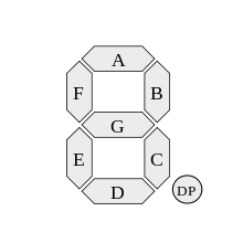
First row is 0123456789ABC, corresponding to each of the 13 inputs. Only the inputs which are currently HIGH have their corresponding characters printed. Inputs which are LOW are represented by a blank space.
Second row displays LO while outputs are LOW, and HI 888 while outputs are HIGH.
For your reference, the Gotek floppy header has the following pin assignments:
| Pin | Signal | Pin | I/O | Signal |
|---|---|---|---|---|
| 1 | Ground | 2 | O | Disk Change / Density |
| 3 | Ground | 4 | - | Reserved |
| 5 | Ground | 6 | - | Reserved |
| 7 | Ground | 8 | O | Index |
| 9 | Ground | 10 | I | Drive Select 0 |
| 11 | Ground | 12 | I | Drive Select 1 |
| 13 | Ground | 14 | - | Reserved |
| 15 | Ground | 16 | I | Motor On |
| 17 | Ground | 18 | I | Direction |
| 19 | Ground | 20 | I | Step |
| 21 | Ground | 22 | I | Write Data |
| 23 | Ground | 24 | I | Write Gate |
| 25 | Ground | 26 | O | Track 0 |
| 27 | Ground | 28 | O | Write Protect |
| 29 | Ground | 30 | O | Read Data |
| 31 | Ground | 32 | I | Side/Head Select |
| 33 | Ground | 34 | O | Disk Change / Ready |