Host Platforms
Computers:
- Acorn Archimedes
- Acorn BBC Micro
- Amstrad CPC
- Amstrad PCW
- Amstrad PPC
- Atari ST
- Commodore Amiga
- DEC
- Dragon
- IBM 3174
- IBM PC
- IBM PS/2
- Kaypro
- Memotech
- Microware
- MSX
- NEC PC-98
- Sharp
- Sinclair QL
- Spectrum
- Tandy Color Computer
- TI-99/4A
- TSC Flex
- UKNC, DVK
Electronic synthesizers:
- Akai
- E-mu ESI-32
- Ensoniq
- General Music (GEM)
- Korg
- Kurzweil
- Roland
- Sequential Circuits Prophet 3000
- Yamaha
Embedded & Industrial:
Most systems require Shugart interface (the default) and select line 0 (jumper on S0). Such systems will work out of the box with a factory-fresh Gotek programmed with FlashFloppy firmware, requiring only a physical jumper at the rear to be moved from S1 to S0.
If this does not work then also try the following:
- Jumper at S1 only
- Jumpers at JC and S0
- Jumpers at JC and S1
If the system still does not work and the Gotek green LED is permanently lit then you may need to try connecting the ribbon cable 'upside down'.
This gives a total of eight possible jumper/ribbon configurations to try, and there are further instructions for certain specific systems listed below.
A final note: In most cases except when connecting to an IBM PC, FlashFloppy requires a straight floppy cable with no 'twist' between the connectors. If you do use a twisted cable, you should jumper MO instead of S0. The exception is the one case that the twist was designed for: connecting FlashFloppy as Drive A to an IBM PC or compatible.
To use ADFS D/E/F sector images, which usually have suffix ADF, you must explicitly configure the host type in FF.CFG as Amiga sector images share the same suffix:
host = acorn
Some ADF images may not be exactly the correct size (usually 800kB or 1.6MB) and thus not be detected as valid by FlashFloppy. These can be modified to the exact correct size using the dd utility on Mac or Linux. For example, for an 800kB image:
# dd if=/dev/zero of=fixed.adf bs=5120 count=160
# dd if=bad.adf of=fixed.adf bs=5120 count=160 conv=notrunc
Note that on A3xx/A4xx/R140 models the orientation of the IDC connector is flipped 180 degrees on the motherboard (Pin 1 becomes Pin 34, Pin 2 becomes 33 etc.) so will require a standard cable to be turned over. A3000/A540/R2xx models have standard orientation.
These use WDC-177x controlled double density drives for up to 800kB capacities so use:
interface = shugart
The A3xx/A4xx models drive pin 1 so to avoid 'Drive Empty' messages and damaging the IC29 line driver they require pin 1 (Disc Eject) to be disconnected, either on the cable or on the Gotek since the standard Gotek grounds this signal along with the rest of the odd pins.
A3xx/1, A4xx/1 & R140 models have the same issue which can alternatively be deactivated by removing LK9 jumper if it is fitted.
These use PC-compatible HD drives for 1.6Mb capacities and require the
drive-select jumper at position S1, and interface = ibmpc in
FF.CFG.
Also these models may use index pulses to determine whether a disk is inserted in the drive. If you are seeing spurious "Drive Empty" messages then add the following to FF.CFG:
index-suppression = no
BBC Micro systems using the original single-density 8271 controller
require regular index pulses to avoid disk-not-ready errors
(described here). These errors are reported on the
video screen as Drive fault 10 at xx/xx.
This issue is solved by specifying the following FF.CFG option:
index-suppression = no
Akai systems require explicit configuration in FF.CFG to recognise IMG files correctly:
host = akai
The correct jumper selection is usually S0, with the following interface selections in FF.CFG, depending on model:
interface = ibmpc-hdout
interface = akai-s950
interface = ibmpc-hdout
pin34 = dens
interface = shugart
These hosts send a signal to the floppy drive on pin 2, hence this pin
must be configured nc:
interface = shugart
pin02 = nc
The Quick Disk version of the FlashFloppy firmware has been tested working on X7000. Follow the Quick Disk connection and installation instructions: Note that you require a jumper at location MO only, and pin ordering of the QD header is reversed. No explicit configuration is required in FF.CFG.
FlashFloppy works with a wide range of CPC DSK images, however compatibility is not perfect with copy-protected images. If you have an original image which does not work, this is often due to 'GAPS protection' where extra data is stored in the gaps between sectors. These images can sometimes be fixed to work with FlashFloppy by running a script included in the FlashFloppy distribution, for example:
# python scripts/edsk_fix_gaps.py crazy_cars.dsk crazy_cars_fixed.dsk
See here for guidance on connecting the CPC's 26-pin cable to the Gotek 34-pin header. Also note that the CPC's power cable has +5v and +12v reversed: you must use an adapter or otherwise somehow insert the power connector backwards. If you do not, you will damage your Gotek and destroy any USB stick that you insert!
Note that Gotek clones designed specifically for CPC (or Spectrum +3) will use the data and power connectors as-is, and the above should be ignored.
WARNING: Some PCW models (PCW9512+, PCW9526, PCW10) use a 26-pin header with integrated power as described here (CPCWiki), requiring an adapter to connect to the Gotek 34-pin header plus power. Please note that this is NOT the same as the CPC 26-pin header, and if you use a CPC-compatible adapter or cable you may damage your Gotek or your PCW!
Later versions of LocoScript and CP/M require Drive A to correctly respond to the Motor signal (Gotek pin 16), by deasserting Ready (Gotek pin 34) when the motor is off. Unfortunately the Gotek usually ignores Motor, and the PCW will hang during boot waiting for the drive to respond correctly. This page (in Italian, so use Google Translate) explains how to modify the Gotek to fix this problem. Section 8.3 of this document gives more technical information on the floppy-drive probe logic which causes this issue.
Alternatively, an option for correct motor emulation is provided in
FF.CFG: motor-delay = 200. Note that a standard Gotek needs a
circuit modification to connect the
motor signal. This is an alternative to the extra external circuitry
described in the previous paragraph.
If the PCW determines that the Gotek is an 80-cylinder (80c) drive, it will support 40c disk images by double-stepping the drive heads to move between tracks. This is because 40c disks have their tracks twice as far apart as on 80c disks. The effect on Gotek is that 180k DSK files will give disk errors, as the double steps will skip every other track in the disk image!
There are two possible solutions:
- Convert to HFE: Using the HxCFloppyEmulator software, Load the DSK image, then in SD HxC Floppy Emulator settings tick the Double Step box. Now Export your DSK image as an HFE file. The resulting HFE file is flagged to expect double-step behaviour.
- Track-Double the DSK: A script is provided to double up the tracks in your DSK file. The resulting 'fixed' DSK file will respond correctly to the PCW's double-step behaviour.
# python scripts/edsk_double_step.py my.dsk my_fixed.dsk
Although IBM PC compatible, the Amstrad PPC (Portable PC) series uses the Shugart floppy interface, and thus require a jumper at position S0 only.
If you find that large file writes, and disk copies, to the Gotek drive
cause "Not Ready" errors, then you should add write-drain=eot to
your FF.CFG file (#320).
No special configuration is required. Interface is Shugart (the default) and drive-select jumper should typically be at position S0.
To replace an existing Amiga internal drive usually requires a jumper
on S0 only. One exception are Escom A1200 boards, which are modded to
use PC drives: if you have one of these then you require a jumper on
JC (or interface = ibmpc in FF.CFG). For improved compatibility you
can undo the Escom mod as described by RetroGameModz.
Replacing an external drive depends on the enclosure or cable being used. Amiga external drive enclosures usually include the circuitry to allow the Amiga to identify the presence of the drive. In this case the Gotek with S0 jumper is usually a straight swap for the old floppy drive. If using a passive cable such as this Ebay item then be aware that this identification circuitry is missing, but for arcane reasons identification will typically happen to work as long as the Gotek has an image mounted when the Amiga boots. If you are having problems with your drive being identified, see Drive Identification.
Amiga Kickstart versions 2.05 and later support high-density disks with 1760kB formatted capacity. This enhancement required a customised (and nowadays expensive!) HD drive modified to rotate at half speed and emit a special ID sequence to the Amiga when an HD disk is inserted.
FlashFloppy supports this enhancement for 1760kB ADF images, but the high-density ID sequence must be explicitly enabled in FF.CFG (see Drive Identification).
If using an Amiga external drive enclosure, please bear in mind that the enclosure's interface board usually emits a fixed double-density ID sequence which will make HD images unreadable. In this case you must disconnect the enclosure's ID circuitry on its interface PCB:
- Cut the PCB connection to external connector, pin 1.
- Connect a jumper wire between internal connector pin 34 and external connector, pin 1.
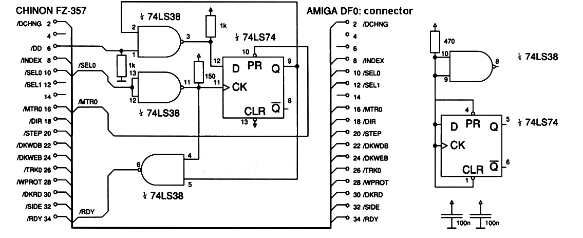
Amiga hosts expect a drive ID sequence from external and
Amiga-high-density drives on pin 34 of the floppy interface when the
drive motor is disabled (pin 34 carries the Ready/RDY signal
when the drive motor is enabled). In contrast, FlashFloppy's default
interface mode (interface = shugart) permanently attaches RDY
to pin 34, regardless of motor.
This default behaviour usually works fine:
- Drive ID signalling is not required for double-density DF0 operation
- External drive enclosures often implement the drive-ID circuitry
- A mounted disk image asserts RDY which happens to match the Amiga ID sequence for a double-density drive anyway
However, there are a couple of cases where this default behaviour may not suffice:
- Using high-density disk images (1760kB formatted capacity)
- Using as an external drive with a passive interface cable, if FlashFloppy does not assert RDY during boot (eg. eject-at-power-on, no USB stick, or too slow to initialise)
In the above cases FlashFloppy can be configured to emulate the drive ID in several ways:
The following line in FF.CFG will force FlashFloppy to emit the drive ID on pin 34 at all times:
interface = amiga
When high-density images are not being used, and when FlashFloppy is
being used as DF0 or without problems as DF1-DF3, then the default
interface type (interface = shugart) is preferred as this gives more
accurate behaviour on pin 34 when the drive motor is on.
This method requires FlashFloppy running on an AT32F435 microcontroller, an additional jumper strap at position MOR, and the following lines in FF.CFG:
interface = amiga
motor-delay = 500
This correctly multiplexes ID and RDY signals onto pin 34 based on motor, synchronises the high-density ID signal to motor off, and emulates a realistic 500-millisecond delay from motor on to RDY.
Unfortunately only AT32F435-based Goteks emulate these signals fast enough to benefit from this more accurate method.
When interface = amiga is configured in FF.CFG, FlashFloppy outputs
a density signal at jumper pin JC:
- JC floats when a high-density disk is mounted
- JC is LOW in all other cases
This can be used by an external circuit (eg the FZ-357 circuit with some modifications) to generate pin 34 independently of FlashFloppy.
DEC systems require host = dec in FF.CFG for correct IMG layout detection.
The RX33 and RX50 formats are supported.
No special configuration is required in order to use Dragon VDK disk images.
If you wish to use DSK images for Tandy Coco, with appropriate ROM and
disk controller, then you will need host = tandy-coco in FF.CFG.
Requires jumpers at S0 and JC. Works with 1.44MB (HD) IMG files.
Ensoniq systems use custom 800kB and 1600kB disk formats which are supported as IMG files if the host-type is configured in FF.CFG:
host = ensoniq
The common EDE/EDA/EDS/EDT/EDV image formats are not directly supported by FlashFloppy. These can be converted to HFE or IMG format using HxC software. Notes:
-
host = ensoniqis required in FF.CFG for IMG-format support - IMG format is not supported for Mirage or SQ-80 (ie. 880kB) formats
- IMG format is especially preferred for 1600kB HD disks
ASR, MR61, TS: These series require an IBM-PC interface with density-select output. These require a jumper on S0 only, and the following additional line in FF.CFG:
interface = ibmpc-hdout
EPS: Ensoniq EPS series typically requires a jumper on S0 only, and the following lines in FF.CFG:
interface = shugart
chgrst = delay-3
The chgrst line requires v3.3a or later: disk changes may not be detected reliably with earlier firmwares.
SD1: Requires a jumper on S0 only. Standard Shugart interface (requires no configuration in FF.CFG).
GEM systems using the 1.6MB high-density disk format require explicit configuration in FF.CFG to recognise IMG files correctly:
host = gem
GEM WS1: Requires jumpers at S0 and JC. Supports 720kB disk images.
IBM 3174 establishment controllers require the following options in FF.CFG:
host = ibm-3174
interface = ibmpc
Select-line jumper S1 should be installed. The actual drive ID will be determined by the interface cable.
A ready signal is required on pin 4 of the interface. This can be acheived by connecting a diode between pin 1 and 10 of the jumper block as shown below:
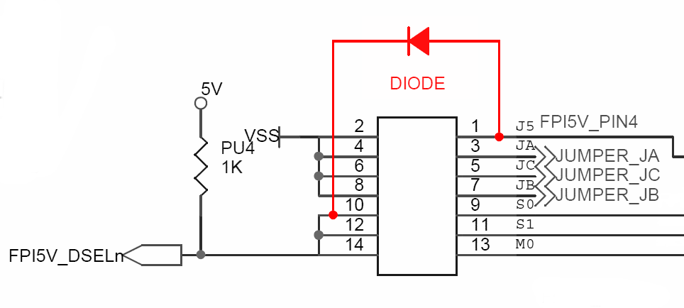
If only a single drive is present then you can install jumper J5 instead of the diode which will cause the ready signal to be permanently asserted.
IBM PC compatibles have a non-Shugart interface which must be explicitly configured in FlashFloppy:
- IBM-PC interface mode must be configured
- Strap jumper JC at the rear of the Gotek; or
- Specify via FF.CFG:
interface = ibmpc
- Strap select-line jumper S1 at the rear of the Gotek
- S0, S2, MO should all be left open
A number of interfaces are used in the various models of PS/2. You may require a 40-pin edge to 34-pin IDC adapter.
Take particular care with models which feature a 34-pin header (eg Model 30): These provide power on pins 3 and 6 which must be disconnected in your interface cable!
Also note: You may need to ground pin 4 (place a jumper at J5) for the Gotek to be detected as a High Density drive.
Kaypro disk images are typically TD0 or IMD format. These can be converted to HFE, or to IMG (raw sector image). In the latter case you will require the format definitions defined in examples/Host/Kaypro/IMG.CFG, distributed with FlashFloppy. Copy this file to your USB stick.
Korg synths require host = akai in FF.CFG for correct IMG layout detection.
Trinity: Jumpers at positions S1 and JC.
Triton: Jumper at position S1 and interface=ibmpc-hdout in
FF.CFG.
KUKA KRC1 uses normal IBM-PC HD drives and PC-format disks. You should place jumpers at locations S1 and JC and you can use PC-formatted 1440kB IMG files.
Kurzweil K2500 requires jumpers at S0 and JC. This is likely to apply across the entire K range.
Memotech systems require the following options in FF.CFG:
host = memotech         # auto-detect IMG layout
index-suppression = no  # SDX/FDX require regular index pulses
Microware OS-9 system requires jumper at S0 and the following lines in FF.CFG. Emulation will work with 1.6MB IMG files.
interface = ibmpc
host = akai
MSX systems require host = msx in FF.CFG for correct IMG layout detection.
PC-98 FDI and HDM disk images are supported directly. For raw IMG files
(rare), host = pc98 needs to be set in FF.CFG.
For most machines the default Shugart interface is correct (jumper only at position S0 at rear of Gotek). Internal pinout varies between PC-98 machines but many use a 26-pin laptop floppy drive connector. Appropriate adapters can be sourced from eBay or wired directly as follows:
(26-pin) -> (34-pin + power)
1 -> 5V
2 -> 8
4 -> 10
6 -> 2
7 -> 12
8 -> 34
10 -> 16
12 -> 18
14 -> 20
15 -> GND
16 -> 22
18 -> 24
20 -> 26
22 -> 28
24 -> 30
26 -> 32
Roland synths typically work out of the box with no special configuration required in FF.CFG, and a jumper at position S0 only at the rear of the Gotek.
OS and System disks will load very slowly using default FlashFloppy settings on some synths. This can be fixed using examples/Host/Roland/IMG.CFG copied to your USB drive, and rename your OS image file to have suffix .os.img. Read the comments in the IMG.CFG file for more information.
E-96, G-800, MT-200, MT-300: Jumper at S0 only, and
interface = jppc-hdout in FF.CFG.
G-1000 Arranger: Jumper at position S1 only.
MT-120: This synth is reported to require jumpers at S0 and
MO, and pin02 = high in FF.CFG.
MKS-100, MT-100, PR-100, S-10, S-20: The Quick Disk version of the FlashFloppy firmware has been tested working on these samplers. Follow the Quick Disk connection and installation instructions, and note that you require jumpers at locations MO and JC.
S-760: Jumper at S0 only, and
interface = ibmpc-hdout in FF.CFG.
Requires host = akai in FF.CFG for correct IMG layout detection.
MZ-800: The Quick Disk version of the FlashFloppy firmware has been tested working. Follow the Quick Disk connection and installation instructions, and note that you require jumpers at locations MO and JC.
The QL has been tested to work with IMG files on all of the floppy interfaces tried so far: Sandy Q-Board, Miracle Systems Trump Card, and Super Gold Card. FF.CFG needs to be configured as follows, otherwise formatting will not work and HD disks won't work on the Super Gold Card (even if FLP_DENSITY is used to manually set the disk type):
interface = shugart
pin02 = dens
All other drive-related settings should be left at their default values.
Note that all interfaces which use the default Q-Jump Toolkit II version of the FORMAT command fail to determine the correct number of sides on in a floppy image and hence format single sided, giving 720 sectors rather than the expected 1440. However, if a pre-formatted image generated by dumping a real floppy or from an emulator is used then everything works. This is due to a trick used by the command to determine the number of sides only working on real hardware, or when using the HFE image format.
The version of FORMAT on the Miracle Systems Gold Card and Super Gold Card use a different algorithm and work correctly. It is unknown if the FORMAT command in SMSQ/e running on a Super Gold Card works or not.
You cannot format ED disk images but, using examples/Host/Sinclair_QL/IMG.CFG copied to your USB drive, you can read and write to pre-formatted IMG images.
Images can be generated using the Qltools utility in the following manner:
Double-sided, double-density: qltools myimage.img -fdd DSKLABEL
Double-sided, high-density: qltools myimage.qlhd.img -fhd DSKLABEL
Double-sided, extended-density: qltools myimage.qled.img -fed DSKLABEL
Qltools is available as a pre-built binary for Linux and Windows and will build with minor modifications on macOS using the Xcode command line tools up to macOS Mojave (Catalina onwards support only 64-bit executables).
FlashFloppy boasts 100% compatibility with the TOSEC collection of DSK images, however some are missing 'weak sector' information and must be fixed up before use. If you find a game title fails to boot then you can fix the image in two ways.
- Using Simon Owen's SAMdisk
# SAMdisk robocop.dsk robocop_fixed.dsk --fix
- Using the Python script included in the FlashFloppy distribution
# python scripts/edsk_fix_speedlock.py robocop.dsk robocop_fixed.dsk
See here for guidance on connecting the Spectrum +3's 26-pin cable to the Gotek 34-pin header. Also note that the +3's power cable has +5v and +12v reversed: you must use an adapter or otherwise somehow insert the power connector backwards. If you do not, you will damage your Gotek and destroy any USB stick that you insert!
Note that Gotek clones designed specifically for CPC and Spectrum +3 will use the data and power connectors as-is, and the above should be ignored.
Requires host = tandy-coco in FF.CFG to indentify DSK images as JVC format.
Requires host = ti99 in FF.CFG to identify DSK images as V9T9 format.
Flex disks can have mixed density (single-density track 0, double-density everywhere else). Suitable formats are defined in examples/Host/TSC_Flex/IMG.CFG distributed with FlashFloppy. Copy this file to your USB stick.
These Soviet PDP-11 clones have a modified IBM track format which must
be explicitly configured via host = uknc in FF.CFG.
This vintage synthesizer uses an old drive type with an explicit Disk Change Reset signal on pin 1 of the ribbon cable. This requires a hardware modification to the ribbon cable or Gotek, as described in the Hardware Mods.
It also requires the following line in FF.CFG:
chgrst = pa14
Reported working as an IBMPC drive (jumpers at S1 and JC).
Reported working with a custom adapter cable to interface to the Yamaha's 24-way FFC connector. Please note you will need soldering experience and the risk of damage is high if you don't know what you're doing! To my knowledge no pre-made adapter kit exists.
Reported working as a Shugart drive (jumper at S0 only) using HFE image files.
Requires connecting or jumpering the Motor signal. On SFRKC30AT4.35 you should strap jumper position MOR. On other Gotek models a hardware modification is required. In addition you will require a jumper at location S0 and the following line in FF.CFG:
motor-delay = 500
Reported working as an IBMPC drive (jumpers at S1 and JC).
Reported working as an IBMPC drive (jumpers at S1 and JC). IMG files on the USB drive need to be formatted using the RM1x Disk job menu.
Uses a 26-pin connector with integrated power, for which you will need an adapter to convert to 34-pin plus power. A jumper is then required at S0.