UserGuide - sci-bots/dropbot-v3 GitHub Wiki
- DropBot DB3-120 kit
- Install MicroDrop
- Connect DropBot
- Run the on-board hardware diagnostic tests
- Attach the Webcam
- Insert a DMF chip
- Align webcam video to device drawing
- Program electrode actuation
- Load liquid onto the chip
- Dispense, move, mix, and split droplets
- DMF chip specifications and sample mask

You should have received the following items with your DropBot kit (see here for a larger image):
- DropBot DB3-120 instrument
- +12V power supply
- Test board
- USB A/B cable
- 3x DMF chips
- Device spacer
- Webcam
- Webcam holder
- Test tubes containing:
a) PBS + 0.1% Tetronic 90R4: aqueous “wash buffer” solution.
b) Propylene glycol: our preferred liquid for testing and demonstrations. It has a much lower evaporation rate relative to water which means that you can manipulate droplets for several hours before they become too small. It also has low surface tension making it easy to load into reservoirs and split. Finally, in our experience, chips tend to last longer using propylene glycol relative to aqueous solutions (e.g., we experience less surface degradation and electrolysis). Note: propylene glycol is more viscous than water, so it tends to move more slowly.
MicroDrop is a Windows app for programming and controlling the DropBot and the latest release can be downloaded here.
MicroDrop currently supports Windows 10.
- Plug +12V power supply into wall outlet.
- Connect +12V power supply to DropBot.
- Connect USB cable between PC and DropBot.


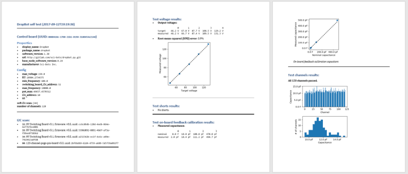
Once you have MicroDrop installed and have connected the DropBot, the next thing you will want to do is test that your hardware arrived in a working state:
- Launch
MicroDropfrom theWindows Startmenu. - From the
Tools\DropBotmenu, selectRun all on-board self-tests.
Note: If you have any trouble connecting to the DropBot, please see the Troubleshooting guide.
The software will pop up a wizard showing you how to insert the test board into your DropBot. These tests confirm that:
- The high-voltage source is working.
- The feedback-sensing circuit is working.
- There are no short-circuits on any of the actuation channels.
- All actuation channels are functional.
See below for an example report:
Attach the webcam to the DropBot as shown below:

Note: For (optional) advanced control over webcam settings (e.g., fixed focus), download the Logitech Webcam Software from the Logitech C920 support page.
The following steps are illustrated in the figure below (see here for a larger image):
- Pick up DMF chip by edges, being careful not to touch the surface.
- Insert DMF chip into front of DropBot, and;
- ...push forward until it hits the back of the chip guide.
- Insert device spacer under the chip guide surface.
- Push device spacer in as far as possible.

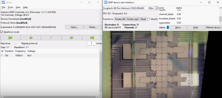
See this screencast demonstrating how to register the webcam video to align with the device drawing in the DMF device user interface.
| Action | (click for full-size image) | |
|---|---|---|
| Actuate electrodes | Click with left mouse button to toggle electrode on/off. |  |
| Draw route | Click and drag to draw route following mouse cursor. |  |
| Draw mix | End a route at the starting point to draw a mixing route/cycle. |  |
| Auto route | Hold <alt>, click on source electrode, and release on target electrode to automatically find a route between the source and target. |
 |
| Adjust layer alpha | The alpha/opacity of each layer (e.g., connections, electrode shapes, labels) can be adjusted independently. |  |
| Parameter | Description |
|---|---|
 |
Length of time (in seconds) to apply each actuation |
 |
Actuation voltage (in RMS voltage) |
 |
Actuation frequency (in Hz) |
| Parameter | Description |
|---|---|
 |
Number of seconds to loop cyclic routes |
 |
Number of times to loop cyclic routes |
 |
Number of consecutive electrodes to actuate along route, e.g., trail length of 2: 
|
- Electrodes actuations are only applied to DropBot when either:
a) realtime mode is enabled (see below; note that duration is ignored); or
b) protocol is run by pressing the "play" button. -
Routes are only executed when the protocol is run by pressing the "play" button.
- Actuation duration is applied for each actuation along route.
To load liquid on the DMF chip:
-
Enable realtime mode. This allows you to control the actuation state of electrodes by left-clicking on electrodes in the device view.
-
Actuate a reservoir electrode using the MicroDrop software by left-clicking on it with your mouse. Note that you may need to adjust the voltage depending on the liquid and the chip. Generally, it is best to start with a low voltage (e.g., 80-90V) and increase it as necessary. Using too high of a voltage can reduce the lifetime of the chip.
-
Manually pipette ~6 uL of liquid at the edge of the top plate over the reservoir electrode.
Note: Liquids must have a sufficiently low surface tension to be loaded into reservoirs (e.g., the surface tension of pure water is too high to be drawn between the two hydrophobic plates). You can lower surface tension by adding surfactants (e.g., Tetronic 90R4). Reducing the surface tension also makes it easier to dispense/split drops.
Try out the basic droplet operations (dispense, move, mix, and split) by following along with this video playlist.

The DropBot DB3-120 kit includes sample DMF chips
with a 90-pin electrode array configuration.
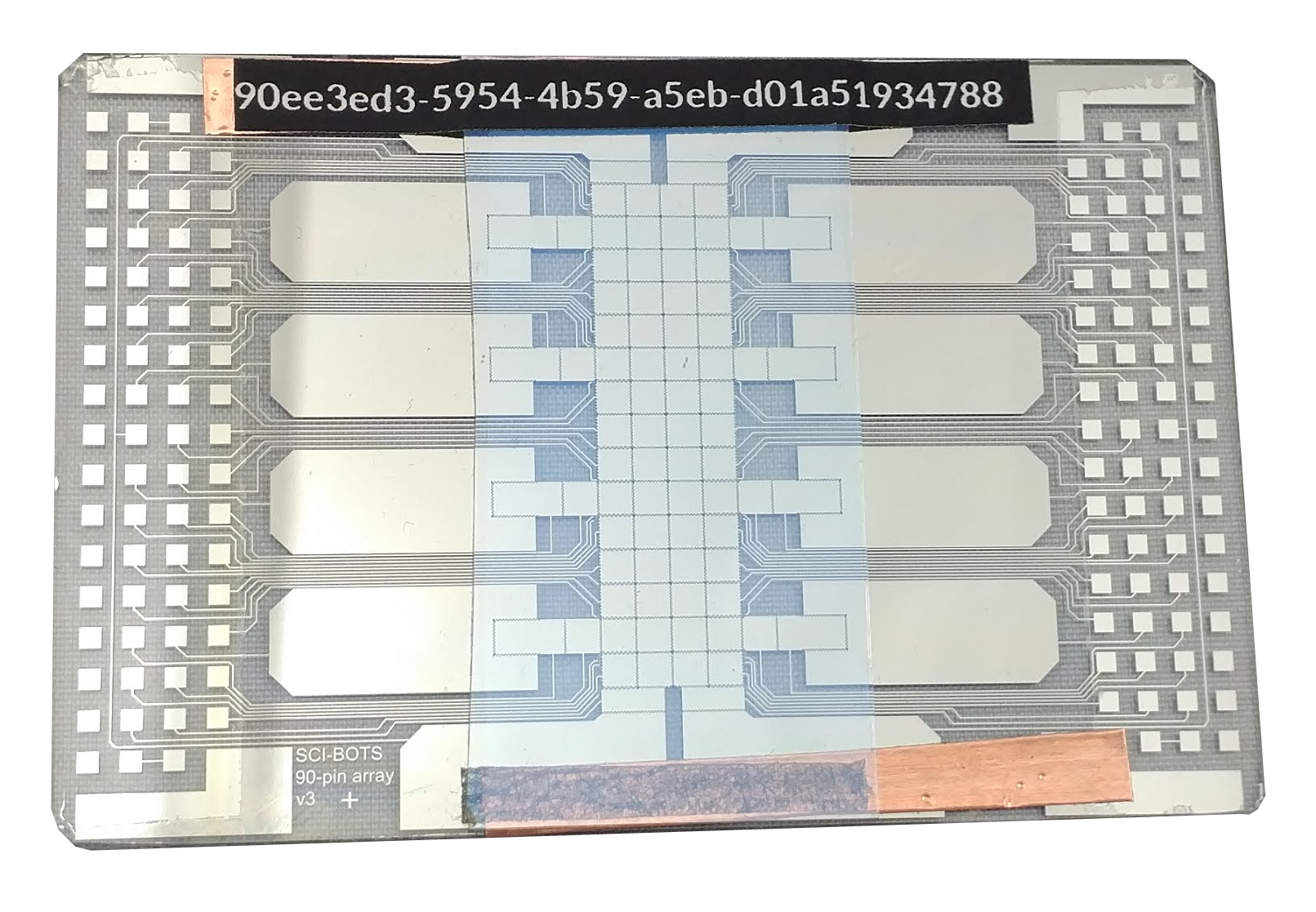
These chips are available for purchase from the Sci-Bots online shop.
Note: custom chips may also be used with the DropBot DB3-120 system.
Please see the DropBot DB3-120 chips specifications for more information.