driveboard_v1403 - nortd/lasersaur GitHub Wiki
Driveboard v14.03 (and earlier)
Home | Driveboard | Wiring Guide
NOTE: For the latest Driveboard see: Driveboard Element
NOTE: We have detailed instructions and schematics on the Wiring Guide page.
The Driveboard is the main electronics board of the Lasersaur (successor of LasaurShield). It interfaces all the electronics components and runs the Lasersaur software. This makes the Lasersaur fully controllable from any modern web browser over the local network (ethernet, wifi). The software is modular (firmware, backend, frontend) and allows for simple hacking and modding. The board is z-axis ready but is typically only operated with the x- and y-axis stepper drivers and motors.
Features
- three stepper drivers (x,y,z)
- two limit sensors per axis
- two door sensors (one redundant)
- one chiller sensor
- emergency interlock (e-stop) via solid state relay
- e-stop doubles as system on/off
- two 24V, 1A, opto-isolated outputs (e-valve, solenoid actuators)
- all sensor and control wiring with shielded Cat5 patch cables
- hard-logic laser safety system (laser is switched off reliably by the following events: door open, chiller failure, limits hit)
- zero software install solution, full control with any modern browser (embedded web app)
- build for easy hacking and modding in mind (minimal real-time firmware, powerful Linux-based UI programing, future expandability like camera, wifi, etc ...)


Required Parts
The following parts are required to get the Driveboard working. All of these items are in the Lasersaur BOM:
- Two GeckoDrive G201X stepper drivers
- GeckoDrive G203V are also fully compatible.
- A BeagleBone Black (BBB)
- loaded with LasaurApp
- Experimental headers for the RaspberryPi are also provided.
- Two PSUs
- 24V, 3A
- 5V, 3A
- Standard shielded Cat5 Patch cables for wiring (SFTP, 26-24AWG, TIA/EIA-568-A or B)
- 4x 1m (1x limit, 1x laser, 1x e-stop, 1x e-valve)
- 5x 2m (2x limit, 1x door, 2x stepper)
- 3x 3m (1x limit, 1x door, 1x chiller)
- Power chords with C-14 plug (same cable what most desktop computers use)
- 1x main power
- 2x internal wiring (cut as necessary)
- both interlocks can also be connected with a jumper
- E-Stop
- (optionally) E-Valve
- (optionally) acrylic mount/cover sheets

Power Wiring
The power wiring involves AC input, 24V PSU, 5V PSU, laser PSU, and frame. This is all about the screw terminals on the left side of the Driveboard. The recommended wire gauge is 18AWG (standard power cord gauge). All three PSUs are powered through the board.
- AC input connects to
AC_in_1,AC_in_2, andGND_in - The laser PSU connects to
AC_laser_psu_1,AC_laser_psu_2, andGND_laser_psu - The 24V PSU connects to
AC_24V_psu_1,AC_24V_psu_2, andGND_24V_psu. The 24V output connects toDC_in_24V+, andDC_in_24V-. - The 5V PSU connects to
AC_5V_psu_1,AC_5V_psu_2, andGND_5V_psu. The 5V output connects toDC_in_5V+, andDC_in_5V-. - The Lasersaur frame connects to
GND_frame. Be aware that the aluminum extrusions have a non-conductive coating. Either sand or connect to an angle bracket. Alternatively if the laser PSU casing has connectivity to the frame (sanding may be required), the Driveboard will be grounded too.
The screw terminals labeled air_assist+, air_assist-, aux1_assist+, aux1_assist- are optional and redundant to the assists jack. Typically the assists are wired with a Cat5 patch cable.
Sensor and Control Wiring
Most of the sensor and control wiring is done with shielded Cat5 patch cables (ethernet cables). This has the advantage of not having to assemble plugs while still being affordable and highly available. The following shorthands are the colors of the patch cable leads: wgr,wor,gr,or,bl,br,wbr,wbl
- x1 limit (left)
- cable length: 3m
- wgr,wor -> either side of the sensor (=vcc 1,3)
- gr,or -> either side of the sensor (=sig 2,6)
- (wbr,br must not connect to wbl,bl) (=gnd 7,8 =sig 4,5)
- x2 limit (right)
- cable length: 2m
- (connect same as x1)
- stepper_x (Nanotec)
- cable length: 2m
- wgr, wor -> orange (=A 1,3)
- gr,or -> brown (=A' 2,6)
- bl,br -> red (=B 4,8)
- wbr,wbl -> yellow (=B' 7,5)
- y1 limit (rear)
- cable length: 1m
- (connect same as x1)
- y2 limit (front)
- cable length: 2m
- (connect same as x1)
- stepper_y (Nanotec)
- cable length: 2m
- wgr, wor -> green (=A 1,3)
- gr,or -> black (=A' 2,6)
- bl,br -> red (=B 4,8)
- wbr,wbl -> blue (=B' 7,5)
- red-white -> blue-white
- black-white -> green-white
- door1
- cable length: 3m
- wgr,wor -> either side of the sensor (=vcc 1,3)
- gr,or -> either side of the sensor (=sig 2,6)
- (wbr,br must not connect to wbl,bl) (=gnd 7,8 =sig 4,5)
- door2
- cable length: 2m
- (connect same as door1)
- laser
- cable length: 1m
- gr,or -> P or WP (=dis 2,6)
- bl -> H or TH (=pwm 4)
- wbr,br -> G or GND (=gnd 7,8)
- wgr,wor -> not used (=vcc 1,3)
- wbl -> not used (=aux2 5)
- Also on the laser PSU connector: 5V(pin1) -> IN(pin6)
- See Laser Adjustment page for output calibration.
- chiller
- cable length: 3m
- wgr,wor -> H3 (=vcc 1,3)
- gr,or -> H1 (=sig 2,6)
- (wbr,br must not connect to wbl,bl) (=gnd 7,8 =sig 4,5)
- e-stop interlock
- cable length: 1m
- wgr, wor -> e-stop_1 (=1,3)
- gr,or -> e-stop_2 (=2,6)
- e-valve
- cable length: 1m
- wgr,wor -> air_assist+ (=1,3)
- gr,or -> gnd (=2,6)
- bl,br -> gnd (=4,8)
- wbr,wbl -> aux1_assist+ (=7,5)
- z1, z2, stepper_z (optional)
- (analogous to x- and -y-axis)
Current Set Resistors
The Driveboard (assembled version) comes with current set resistors that match the stepper motors of the current BOM. If you are upgrading an older build or using alternative stepper motors for some other reasons make sure to adapt these resistors. The resistors are located right to the stepper drivers. Their value is calculated as follows, "I" being the current rating of the motor in Ampere:
R (kOhm) = 47*I/(7-I)
Alternatively you can also remove these resistors and use the dip switches of the stepper driver to set the current. See the driver's manual on how to do this.
Software Installation
See Lasersaur Software.
Safety Systems
During operation the Lasersaur hardware (hard-logic safety) and firmware monitor various sensor events and make sure safe operation is maintained.
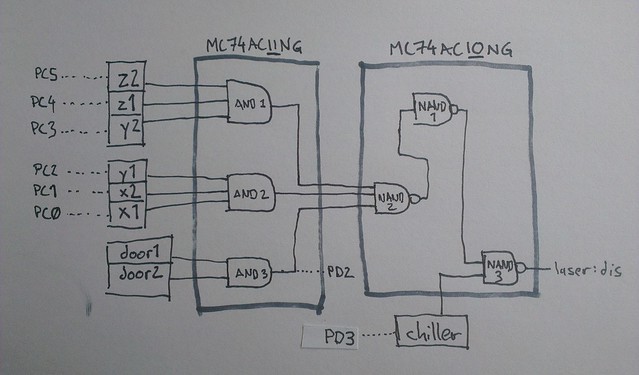
- hardware safety functions (Driveboard logic):
- the laser is disabled via the "laser:dis" pin when any of the following happens
- any limit interlock is open
- chiller interlock is open
- any door interlock is open
- the laser is disabled via the "laser:dis" pin when any of the following happens
- firmware safety functions:
- the controller is put into "stop mode" when any of the following happens:
- any of the limit interlocks opens
- serial data contains a '!' character
- the controller resumes from "stop mode" when serial data contains a '~' character. LasaurApp sends this character when pressing 'Cancel' or 'Homing Cycle'.
- the controller is put into "stop mode" when any of the following happens:
- e-stop
- when open the following subsystems are turned off:
- 5V board power
- Laser PSU AC line (via SSR)
- 24V PSU AC line (via SSR)
Driveboard Safety Logic in Detail
Various Mods (optionally)
Using an Arduino instead of a BeagleBone
Usually the BeagleBone runs LasaurApp and sends G-code to the Driveboard's Atmega chip. If no BeagleBone is available you can also run LasaurApp on your computer. An Arduino's USB-to-Serial converter can then be used for connectivity (in fact pretty much any USB-to-serial converter can be used).
For this to work you need to remove the Atmega chip from the Arduino and connect three pins to the Driveoard: TX, RX, and GND. You can find these pins on the Driveboard's "serial" header (v13.03 and newer). Connect as such: Arduino:TX -> Driveboard:RX, Arduino:RX -> Driveboard:TX, Arduino:GND -> Driveboard:GND. (If you want to power through the Arduino, also connect 5V pins)
Then start LasaurApp on your computer by running python backend/app.py. The browser-based GUI should then open automatically.
Troubleshooting
- BeagleBone/BBB does not boot up (no blinking blue LEDs)
- Make sure the BBB is aligned with the Driveboard pins correctly. It must align on the left. Read the notes on the Driveboard.
- Make sure the Driveboard power is 5V (+/- 0.2V). Higher deviations may prevent the BBB from booting up. If necessary adjust the voltage on the PSU via the trimpot ("VR1").
- Homing works but any other motion commands do not move the gantry.
- One of the limit interlocks is not closed. (1) Make sure the z1, z2 pigtail connectors are plugged in. (2) No limit error shows up in the LasaurApp log. If yes, check all the limit switches. They must be closed.
- Take note of the fact that limit sensors and door sensors are not the same part. Make sure not to have swapped them.
- Motion commands move the gantry but no lasing.
- Make sure the chiller interlock and door interlocks are closed.
- Cutting jobs get randomly interrupted and continue with somewhat erradic movement.
- This can be caused by electrical interference with the Driveboard. Specifically a laser tube cable that is wired in close proximity can cause this. Also make sure all the Driveboard's patch cables are shielded (SFTP).