driveboard - nortd/lasersaur GitHub Wiki
Driveboard Element
Home | Driveboard | Wiring Guide | Buy
Driveboard Element is the main electronics board for the Lasersaur. It's a highly capable yet simple device for precise and robust control of the Lasersaur. It is automatically recognized by DriveboardApp on all major platforms and interfaces via USB. Since DriveboardApp also runs on ARM it can easily be network-enabled with a RaspberryPi, Beaglebone, or similar.
Feel free to use it with other CNC machines like mills and plasma cutters.
Changes from Driveboard v14.03
Driveboard Element is the successor of the Driveboard v14.03 and earlier boards. It replaces the Driveboard, the LasaurBBB, and the GeckoDrive G201X stepper drivers. Typically it also does not need an external 5V PSU (but can).
- Designed to be mass-produceable and therefore available preassembled.
- Simpler yet more powerful by moving some complexities into the DriveboardApp.
- Support for both direct (USB) and network-enabled operation. Pretty much plug-and-play with prepackaged DriveboardApp binaries.
- Enhanced shielding and opto-isolation for additional resistance to electrical interference. Aluminum enclosure and wire shields are now tied to the frame ground of the Lasersaur. All control and sensor wiring are opto-isolated.
- The valve supply voltage can now be different from the stepper voltage. This makes it possible to run the steppers with 48V and the valves with 12V, for example (requires cutting a trace).
- Prevents excessive beeping on new RECI laser PSUs.
- No pig tails required on Z1 and Z2 limit inputs when 3rd axis not in use.
Ports
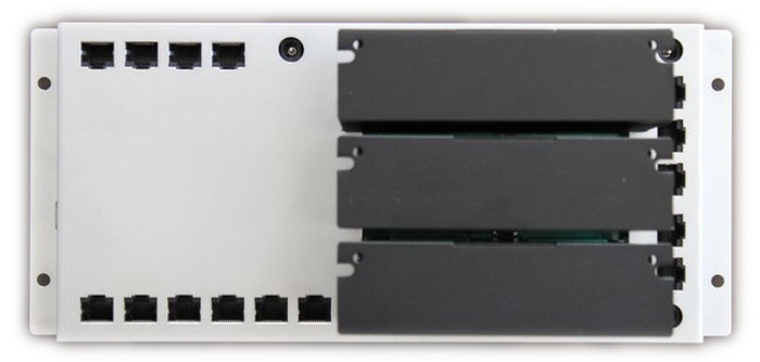
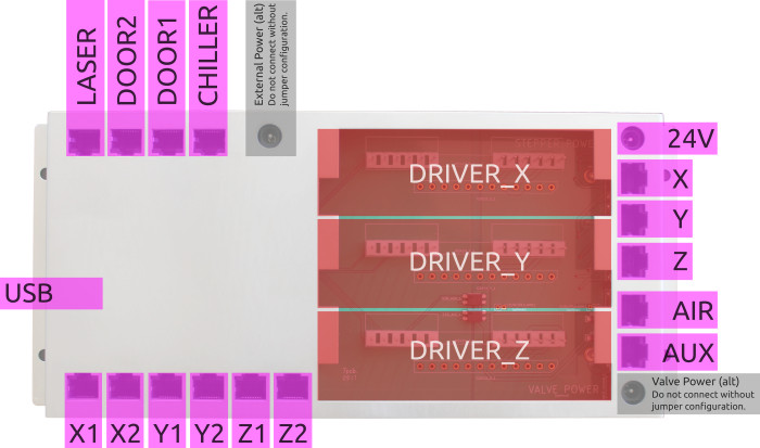
The board has 1x USB type-B, 3x barrel 5.5/2.1mm, 15x RJ45, 3x 12-pin headers.
USB
Port for connecting to the computer running DriveboardApp.
- USB, type-B
Power
The default configuration requires the board to be powered by one external PSU for the stepper drivers. In addition the board draws 5V from the USB line, and 5V from the laser PSU. Former is for the MCU and core logic, and latter for the opto-isolated wiring.
Alternative power setups require certain jumper default traces to be cut. This allows for a different voltage between steppers and valves. And also allows for an external 5V PSU instead of using the 5Vs from the laser PSU.
- Stepper power - 24V - barrel 5.5/2.1mm, 3A (or 75% of summed stepper motor setting)
- Sensor power - 5V - barrel 5.5/2.1mm, 100mA (optional, do not connect without cutting trace)
- Valve power - barrel 5.5/2.1mm, 100mA (optional, do not connect without cutting trace)
Stepper Drivers
The board comes with three stepper drivers. For assmebly instructions and the correct dip-switch settings see the stepper drivers page.
- DRIVER_X, 12-pin header (top)
- DRIVER_Y, 12-pin header (middle)
- DRIVER_Z, 12-pin header (bottom)
Interlocks
These are the inputs for the limit, door, and chiller switches. Switches are expected to be normally closed (NC). When triggered they should disconnect the loop. The point of the RJ45 jacks is to use ethernet patch cables for external wiring: Flexible Cat5 or Cat6 shielded (FTP, STP, or SFTP) patch cables with 26 AWG. Polarity does not matter.
- CHILLER - RJ45
- DOOR1 - RJ45
- DOOR2 - RJ45
- X1 - RJ45
- X2 - RJ45
- Y1 - RJ45
- Y2 - RJ45
- Z1 - RJ45
- Z2 - RJ45

| pin# | color | interlock |
|---|---|---|
| pin-1 | orange-white | pin-1 |
| pin-2 | orange | pin-2 |
| pin-3 | green-white | pin-1 |
| pin-4 | blue | - |
| pin-5 | blue-white | - |
| pin-6 | green | pin-2 |
| pin-7 | brown-white | - |
| pin-8 | brown | - |
Chiller Note: Pin-1 and pin-2 are usually designated as H1 and H3 (polarity is irelevant).
Laser Control
The control wire connects to the control port of the laser PSU. The typical pins are | 5V | TH | TL | WP | GND | IN | and all but TH need to connected as follows. NOTE: This is different from previous boards!!!
- LASER, RJ45

| pin# | color | laser PSU |
|---|---|---|
| pin-1 | orange-white | 5V |
| pin-2 | orange | WP |
| pin-3 | green-white | 5V |
| pin-4 | blue | TL |
| pin-5 | blue-white | IN |
| pin-6 | green | WP |
| pin-7 | brown-white | GND |
| pin-8 | brown | GND |
Stepper Motors
Stepper motors are all driven by energizing two sets of coils. A and A' is one set and B and B' is the other set. This board assumes 2x 26 AWG for wiring and results in a maximum supported nominal current of about 3.5A. Make sure to configure the stepper drivers to match the motors.
- X, RJ45
- Y, RJ45
- Z, RJ45

| pin# | color | motor |
|---|---|---|
| pin-1 | orange-white | A |
| pin-2 | orange | A' |
| pin-3 | green-white | A |
| pin-4 | blue | B |
| pin-5 | blue-white | B' |
| pin-6 | green | A' |
| pin-7 | brown-white | B' |
| pin-8 | brown | B |
Valve Control
Electronically speaking the e-valves are solenoids. Polarity does not matter. While Lasersaur typically uses these to switch compressed air and gas assist either of them can also be used to switch various other peripherials up to 48V and 1A.
- AIR, RJ45
- AUX, RJ45

| pin# | color | valve |
|---|---|---|
| pin-1 | orange-white | pin-1 |
| pin-2 | orange | pin-2 |
| pin-3 | green-white | pin-1 |
| pin-4 | blue | - |
| pin-5 | blue-white | - |
| pin-6 | green | pin-2 |
| pin-7 | brown-white | - |
| pin-8 | brown | - |
Troubleshooting
- After launching the DriveboardApp and connecting to the board all the interlocks trigger.
- Firstly, the sensor wiring needs to be powered with 5V to operate (opto-isolators need it). By default the board gets this from the laser PSU. If the laser PSU is disconnected or off the sensor wiring will not work. Alternatively (e.g. for testing) you can power the 5V input of the board with an external 5V power supply.
- Secondly, this is normal behavior when the sensors are not wired properly/missing.