wiring_v1403 - nortd/lasersaur GitHub Wiki
Lasersaur Wiring Guide (v14.03)
Home | DriveBoard v14.03 | Wiring Guide
NOTE: For the latest wiring guide see: Driveboard Element wiring
The electronics subsystem consists of the DriveBoard v14.03 and its sensing and control peripherials: laser system, gantry steppers, limit switches, door switches, chiller. Additonally it implements a reliable stop mechanism.
WARNING: The laser PSU supplies the laser tube with roughtly 25kV. This poses a lethal risk. Take special care when dealing with the red power cable (rear side of the laser tube) and make sure proper insulation is in place before flipping the on switch. Also be informed that the capacitors inside the PSU may possibly stay charged after disconnecting from grid power.
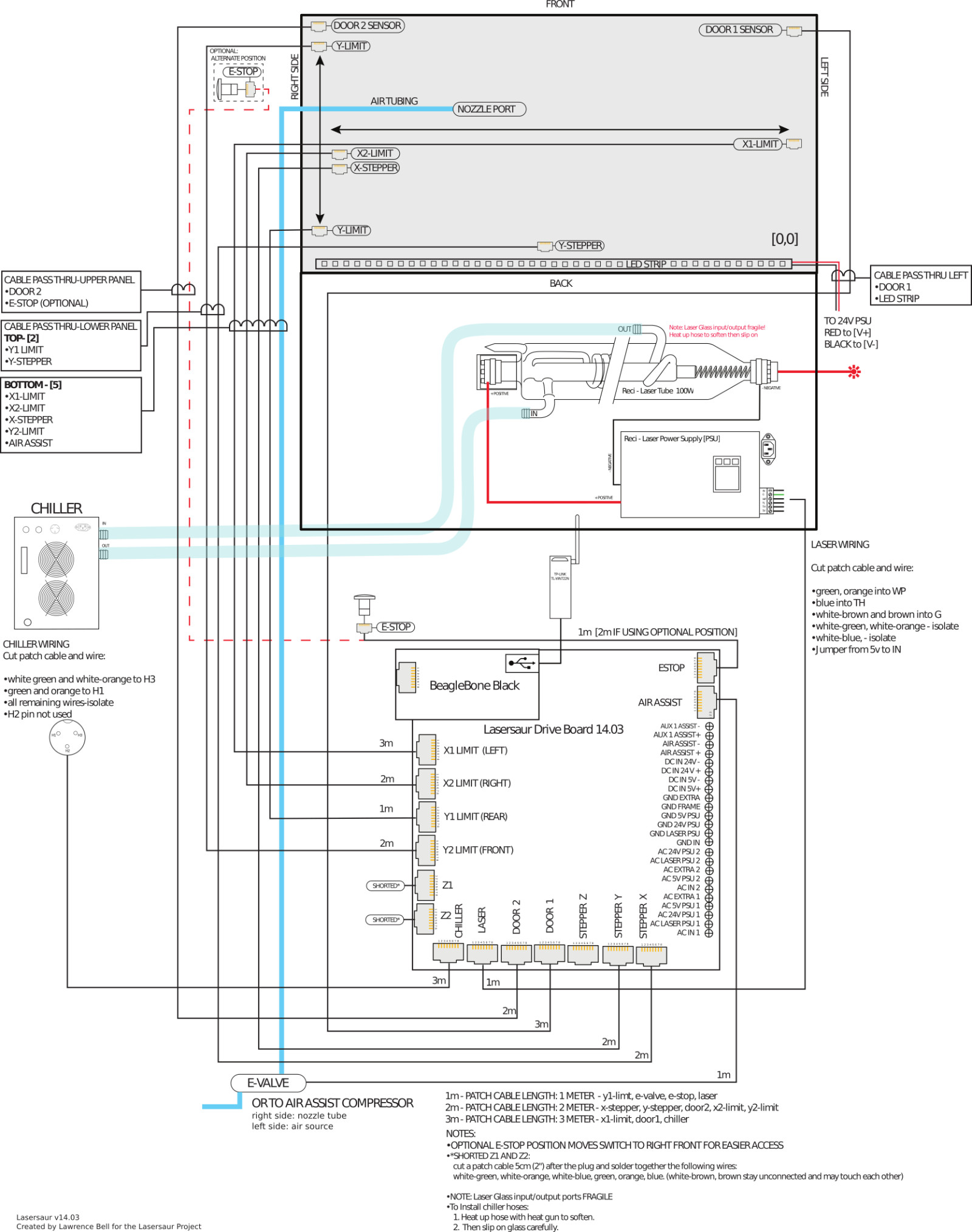
Schematic
Please use this schematic for wiring your Lasersaur. Many details are in the small print and may require you to zoom in and/or download the hi-res version. Soldering/assembly instructions follow below.
Assembly of Control and Sensor Wires
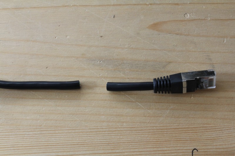
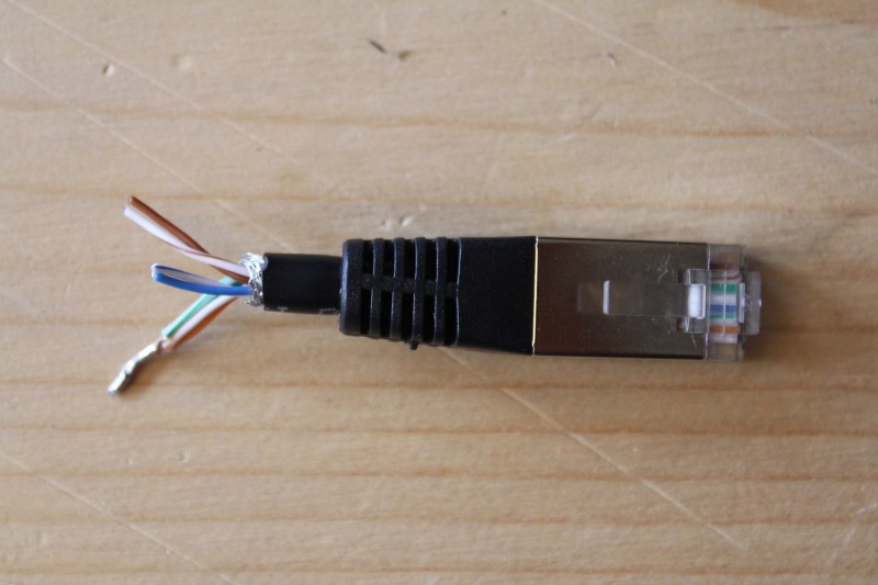
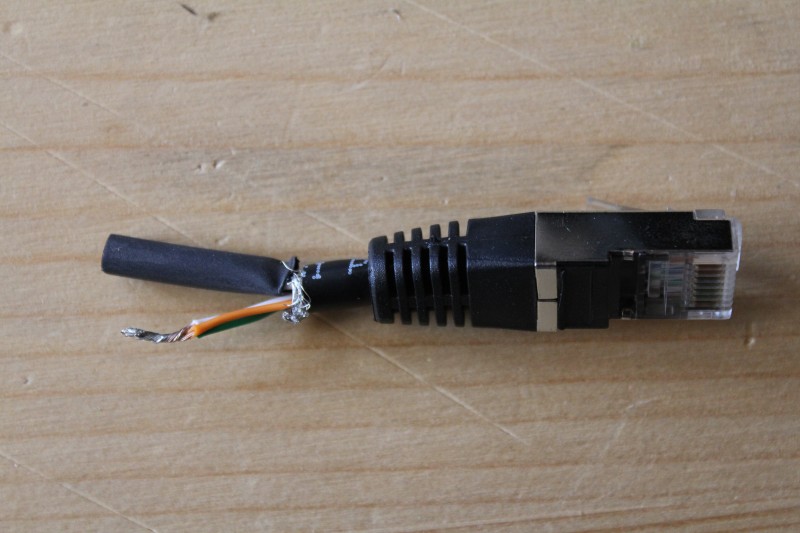
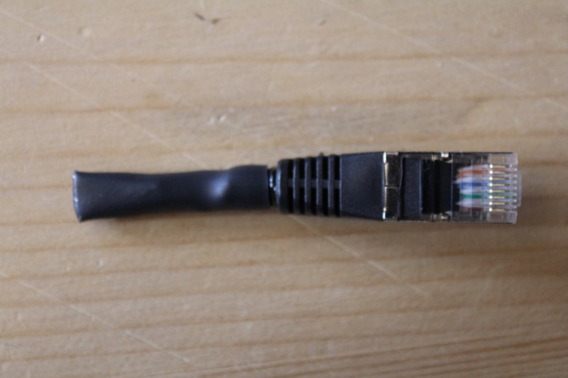
The Driveboard makes extensive use of standard Ethernet patch cables. Laser control, stepper control, e-stop, and all the sensors use them.
Please make sure to use standard patch cables with the following properties: Cat5 , shielded (FTP, STP, SFTP), stranded, 26 or 25 AWG. Cables with solid leads, cables without a shield, or 27+ AWG cross-section are not suitable. (also see: Cat5)
We also recommend the following head shrink tubing with adhesive on the inside: Mouser: 517-EPS400.35048BLK (0.35", 4:1) and 5174-348018 (0.125", 3:1)
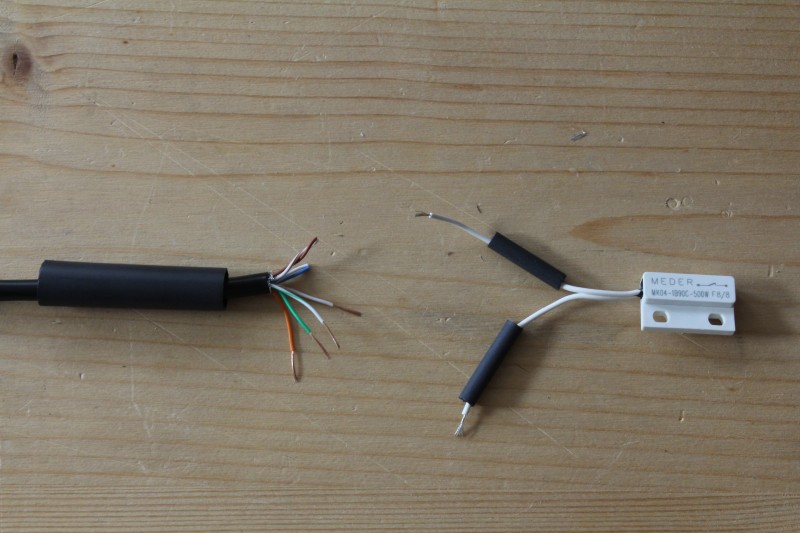
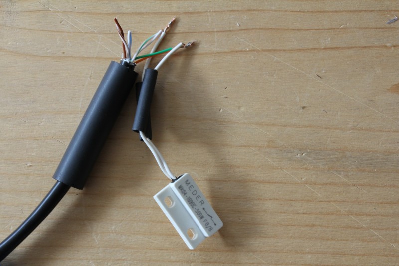
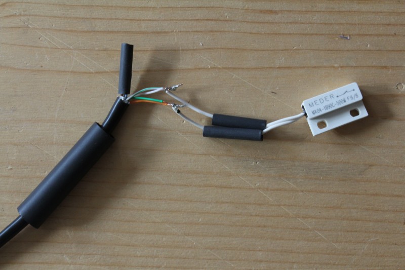
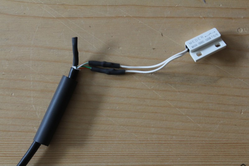
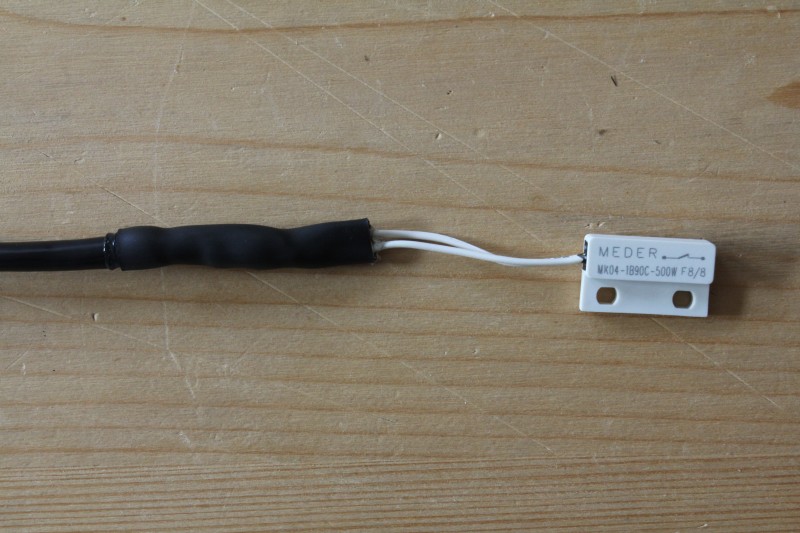
Limit and Door Switches
Limit and door swiches are mostly identical apart from being inversed from each other. The four limit switches (MK04-1B90C-500W) are normally closed (NC). The two door switches (MK04-1A66B-500W) are normally open (NO).
- cable length:
- x1: 3m
- x2: 2m
- y1: 1m
- y2: 2m
- door1: 3m
- door2: 2m
- connections:
- white-green and white-orange connect to either side of the switch
- green and orange connect to other side of the switch
- white-brown and brown must not connect to white-blue and blue
Limit Disable Plugs (z1, z2)
The z-axis limit switches need to be disabled (shorted) when not being used (standard Lasersaur setup). This is accomplished by creating little pig tail plugs for the z1 and z2 limit jacks.
- connections:
- white-green, white-orange, green ,and orange connect.
- white-brown and brown must not connect to white-blue and blue
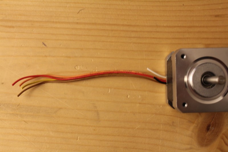
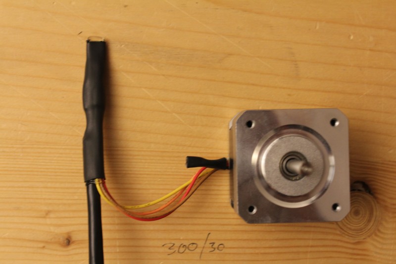
X-Stepper Motor
- cable length: 2m
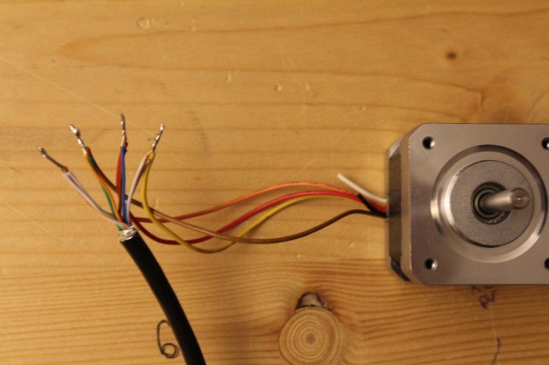
- connections - Vexta PKE244A-L:
- white-green and white-orange connect to red
- green and orange connect to blue
- blue and brown connect to black
- white-brown and white-blue connect to green
- all others disconnected
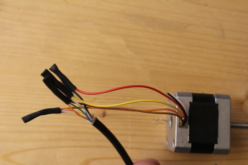
- connections - Nanotec ST4118M1206:
- white-green and white-orange connect to orange
- green and orange connect to brown
- blue and brown connect to red
- white-brown and white-blue connect to yellow
- white must not connect to black (stepper will run too weak)
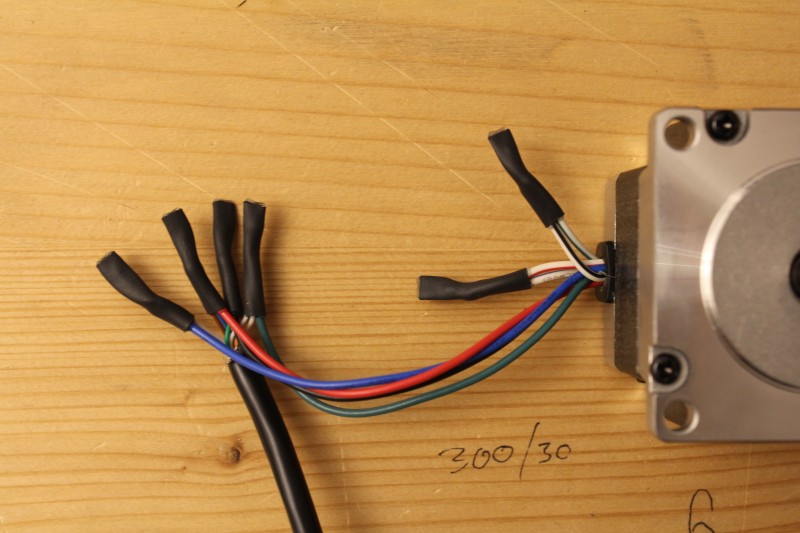
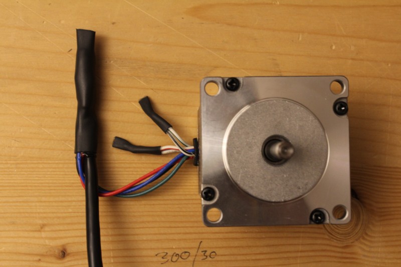
Y-Stepper Motor
- cable length: 2m
- connections - Vexta PK266-03A:
- white-green and white-orange connect to red
- green and orange connect to blue
- blue and brown connect to black
- white-brown and white-blue connect to green
- all others disconnected
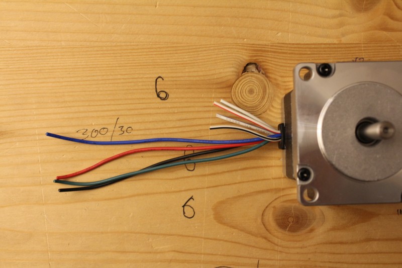
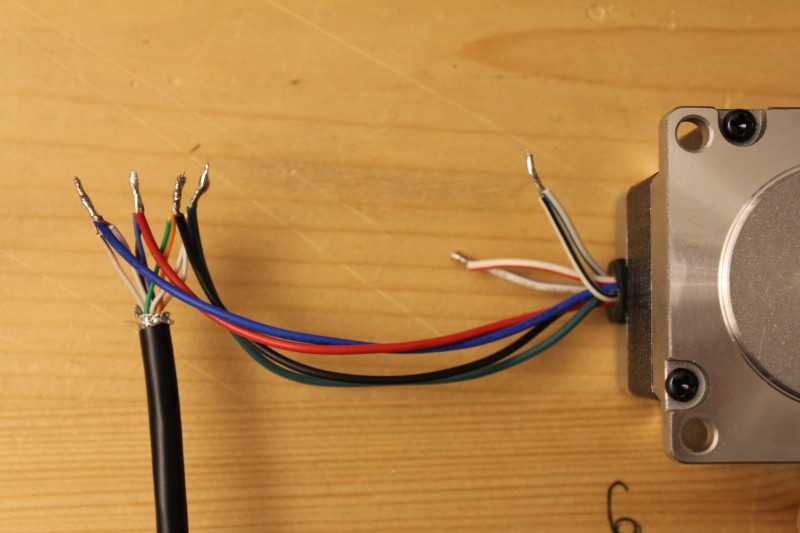
- connections - Nanotec ST5918M3008:
- white-green and white-orange connect to green
- green and orange connect to black
- blue and brown connect to red
- white-brown and white-blue connect to blue
- red-white connects to blue-white (motor loop)
- black-white connects to green-white (motor loop)
Checklist
- Is the high-voltage wire (red wire to backside of tube) properly insulated with the insulation cover? Also is it wired as far as possible away from any other wires and low voltage logic?
- Are the AC wires properly insulated and is the Lasersaur frame grounded?
- Does the E-Stop turn off the machine?
- Has the chiller's water circulations been properly tested and is the tubing mounted in ways not to cause stress on the inlet and outlet ducts.