GunnsFluidCapacitor - nasa/gunns GitHub Wiki

This link is the simplest fluid volume object. This link gives volume, and hence capacitance and fluid mass, to the connected fluid node. The node's fluid contents, mass and volume are all stored within the node object. However the capacitor link controls the node's volume and stores the node capacitance for using in the network system of equations. Nodes with an attached capacitor or similar link are called capacitive nodes, those that do not are called non-capacitive nodes.
The capacitor link has user controls to edit the node volume.
The attached node can model the cooling/heating of a contained gas as it expands/compresses over time. This is called isentropic expansion, and the amount of this effect is tuned with a scale factor owned by this link.
This link does not model heat transfer between the container wall and the node fluid contents. For such a heat flux, the GunnsFluidTank link is needed.
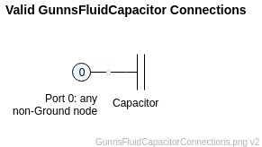
This picture shows the proper way the fluid capacitor is connected to a node:
Port Connection Rules (These are limitations on the port connection to nodes that the link enforces in run-time):
- Port 0 must connect to a non-Ground node.
- Port 1 must connect to the Ground node. This is an optional port in GunnsDraw, and GunnsDraw automatically connects it to Ground when the port connector is omitted.
Other Rules (These are extra rules you should always try to follow):
- Never put more than one capacitor or other capacitive link on the same node.
- Use a GunnsFluidCapacitor instead of the more complicated GunnsFluidTank on nodes where user edits of the node fluid contents are not required and where heat conduction with the container wall is not required.
- The initialFluidState mixture cannot be of mixed-phase - it must either be all gas or all liquid.
- Volume and capacitance provide stability to fluid networks. Links that depend on the last-pass node pressure, such as external supplies, pressure-sensitive valves, pumps & fans, etc, all benefit from having volume in the connected nodes. It is a good idea to account for all of the real volume of the modeled system at the appropriate node locations in the network. Not only do large obvious containers such as tanks and cabins have volume, but small ducts & pipes do as well.
- A "feature" of GUNNS is that any node or nodes that are isolated from any capacitance or pressure/flow sources have their pressure solve to zero. This is because non-capacitive nodes have no volume and therefore zero fluid mass, and pressure is therefore undefined -- the GUNNS solver handles this ambiguity by setting it to zero. To avoid a sensor detecting zero pressure in an isolated node, add some small non-zero capacitance to the node.
- In liquid networks, do not use fixed-volume links such as this and GunnsFluidTank in places where an accumulator would be more appropriate. Because of the fixed volume and liquid imcompressibility, the total liquid mass in the node is essentially fixed, and can't be changed without using excessively large and unrealistic volume. These links are single-phase: liquid volume in this link cannot be displaced by gas volume. For liquid containers where you need to model liquid pouring out and replaced by gas volume, you must use a gas accumulator link. Someday we may have 2-phase tanks and pipes in GUNNS that will handle this automatically, but for now we are limited to using the accumulator links. See the discussion in GunnsFluidAccum.
- Avoid large counts of mass overflows in the node during high flowrate conditions. See the discussion on Mass Overflows below.
Configuration Data Parameters:
- expansionScaleFactor (default = 0.0, must be (0-1)): similar to the same term in GunnsFluidConductor, this scales the temperature change of gas in the attached node in response to compression or expansion over time. A value of 1.0 gives the full theoretical amount of temperature change from isentropic flow theory and a value of 0.0 turns this effect off. This effect only applies to gas phase, and for liquids the term is ignored.
Input Data Parameters:
- malfBlockageFlag (default = false): Initial state of the blockage malfunction activation flag. NOTE: the blockage malfunction is deliberately not implemented in this link and has no effect.
- malfBlockageValue (default = 0.0, must be (0-1)): Initial state of the blockage malfunction activation value.
- initialVolume (default = 0.0 m3, must be >= 0): Initial volume of the container. The volume is usually constant for most objects, but the fluid nodes have the ability to model compression effects due to changing volume, so this term is technically "input data" to allow for changing volume. The volume is usually a well-documented property of a system being modeled and therefore rarely needs to be tuned.
- initialFluidState (default = NULL, must != NULL): Pointer to a Fluid State drawing object (which is a PolyFluidInputData), defining the initial state of fluid within the node. This overrides the node's initial fluid state in the drawing.
-
Mass Overflows: If over any timestep, the mass flowed through a node is greater than
the mass contained in the node at an instant in time, this is called a "mass overflow". For example,
say a node's fluid contents mass is 1.0 kg, and the network executes at 10 Hz, and the flow rate
through the node is 11 kg/s. The integrated flow through the node over the timestep
is 11 kg/s * 0.1 s = 1.1 kg, which is greater than the contained mass of 1.0 kg. This
increments an overflow counter in the node (mMassOverflows). The occasional mass overflow
is not a serious problem, but a sustained continuation of overflows over time is a problem
because it can build up significant temperature (energy) and mass errors, meaning those
properties are not conserved in the network. Overflows are more likely to occur when there
are large flow rates through small volumes over large time steps. To avoid overflow:
- First tune flow rates to be accurate - unrealistically high flow rates are not needed, especially when they can exacerbate the mass overflow problem.
- In general, highly dynamic systems have to be simulated at very small time steps to ensure accuracy. If there are many nodes in the network with a large overflow problem, this is a clear sign that the network needs to be run at a higher execution rate. This is of course very expensive with respect to CPU budget.
- A more practical and common solution is to increase the volume of the overflowing nodes. Although this can make network volumes unrealistically high, this is often an acceptable limitation to ensure conserving mass and energy in the model.
- N/A