GunnsFluidTank - nasa/gunns GitHub Wiki

This link extends GunnsFluidCapacitor with several extra features:
- Temperature & Pressure Edits: Like the volume edit in the capacitor link, these edits
allow the user to directly override or ramp the temperature and pressure state of the fluid
contents of the tank's node. These are the additional edit modes:
- Temperature edit
- Temperature/Total-Pressure
- Temperature/Partial-Pressures
- Partial Pressure Ramp
- More Thermal Effects, such as heat conduction between the tank shell and the contained fluid, and equilibrium with thermal masses in the vessel.
- Delta-Pressure/Delta-Time (dp/dt) Readout: this calculates a total pressure time rate of change truth value from the model for reference. A low-pass filter is included to smooth out model noise.
Other than the above features, this link functions exactly like a GunnsFluidCapacitor. Use the capacitor link when these features aren't needed for your application.
Port Connection Rules (These are limitations on the port connection to nodes that the link enforces in run-time):
- Same as GunnsFluidCapacitor.
Other Rules (These are extra rules you should always try to follow):
- Same as GunnsFluidCapacitor.
Configuration Data Parameters:
- expansionScaleFactor Same as GunnsFluidCapacitor.
- dpdtFilterGain (default = 0, must be (0-1), recommend 0.1): This is a low-pass filter gain for the node's true dp/dt calculation. Lower values smooth out the dp/dt value at the cost of making it more sluggish.
- thermalDampingMass (default = 0 kg, must be >= 0): This is an optional shortcut for modeling the thermal mass of equipment, structures, and parts of the shell that for all intents & purposes can be assumed to always be in thermal equilibrium with the fluid. Heat flows into or out of to the node get split between the node fluid and this mass, damping the expansion of the gas and resulting dp/dt. This fake mass uses the same specific heat as the contained fluid. This parameter is particularly useful for vehicle cabin volumes with sensitive dp/dt sensors, where the damping effect of the equipment and structures in the cabin is important, but we don't want to model them specifically with their own thermal aspects.
- editFluxTarget (default = 0 kg*mol/s, must be >= 0): Edits of various types can create fluid flows into or out of the node as the surrounding network tries to come to equilibrium with the edited node. The Temperature/Total-Pressure and Temperature/Partial-Pressures edits automatically shut off when the net molar flow rate into the node drops below a certain absolute value. This parameter sets that value. Leaving this value = 0 keeps these edits from turning off automatically. Larger values cause the edit to shut off before the system has finished coming to equilibrium. Depending on the network configuration, some nodes always have a non-zero net flux, so this parameter can be adjusted above that value to shut off the edit in the presence of those permanent flows. Edits can always be stopped manually.
- The following parameters configure the tank's own internal calculation of heat flux
between the tank shell and the contained fluid. When both are set to non-zero values, the
tank uses its own calculation, and makes this heat flux value available for optional
integration with a thermal aspect:
- surfaceArea (default = 0 m2, must be >= 0): This is the inner surface area of the tank shell in thermal contact with the fluid. This is used for calculating the conductive heat flux between the shell and the fluid. Both this parameter and shellRadius must be set > 0 for the conduction heat to be applied.
- shellRadius (default = 0 m, must be >= 0): The shell heat conduction model assumes a spherical tank shape, with this parameter as the radius. It can be adjusted along with the surfaceArea to tweak the flux value for other shapes as needed.
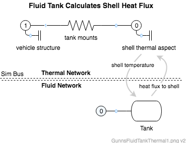
An example of the shell heat integration with the thermal aspect is shown below. In this method, the fluid tank uses its surfaceArea and shellRadius to calculate the heat flux to the shell from the fluid, given the shell temperature from the thermal aspect. The heat flux is passed to the thermal aspect for integration into a new temperature.
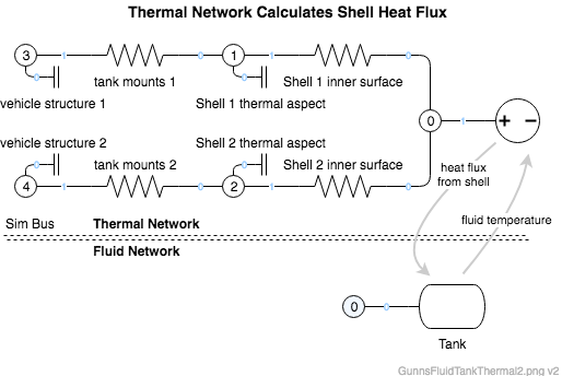
Alternatively, the tank can use a shell heat flux calculated from outside. One example of such an integration with the thermal aspect is shown below. In this method, we leave the fluid tank's surfaceArea and shellRadius zero, and let the thermal network calculate the heat flux to the fluid from the shell. The advantage of this method is that the shell can be divided into multiple pieces sharing portions of the fluid surface. The Tank fluid is represented in the thermal network as a potential (temperature) source, with the fluid network providing the temperature. The thermal network solution results in a flux through the potential source link (from Node 0 to Ground in this picture), which is passed to the fluid network as the conducted heat flux to the fluid.
Input Data Parameters:
- malfBlockageFlag Same as GunnsFluidCapacitor.
- malfBlockageValue Same as GunnsFluidCapacitor.
- initialVolume Same as GunnsFluidCapacitor.
- initialFluidState Same as GunnsFluidCapacitor.
- initialShellTemperature (default = 0 K, must be >= 0): Similar to the wall temperature of valves and other conductor links, this is the initial temperature of the tank shell for heat conduction to the contained fluid.
- biasHeatFlux (default = 0 J/s): This is the initial value of a user-controlled bias heat flux into the fluid. Positive values are heat added to the fluid.
- Same as GunnsFluidCapacitor
- N/A