GunnsFluidAccum - nasa/gunns GitHub Wiki
A hydraulic accumulator is a special tank that pressurizes a liquid system while providing flex to accommodate changes in the liquid density and volume. This link models any accumulator or flexible liquid volume that is not gas-charged. This includes spring-loaded, raised weight, tower, and piston-type accumulators. For gas-charged accumulators and flexible volumes, use the GunnsFluidAccumGas link instead.
Accumulators are important for liquid systems in order to maintain and control the liquid pressure. An accumulator can be used to pressurize a liquid system, either to create flow or to maintain inlet pressure for a pump. A pumped liquid system will usually have some form of flexible volume (accumulator) on the pump's inlet side to avoid cavitating the pump. In the case of a non-loop system where liquid is simply being moved from A to B, accumulator-like containers are needed on both sides to supply & receive the liquid volume.
Just about any liquid network should have at least one accumulator somewhere. Fixed-volume links like the GunnsFluidTank and GunnsFluidCapacitor should never be used by themselves in a liquid system without somewhere else for liquid to go. The reason for this is that liquids are almost perfectly incompressible. This means that it takes a very large increase in pressure to compress liquid even a little bit. The reverse is also true -- in a fixed volume, any slight change in liquid density causes a very large change in pressure. Large changes in pressure are generally bad -- too low a pressure will cause the liquid to boil and cavitate, which can damage pumps, and too high a pressure will burst pipes & containers. Liquid density, just like gas, is affected by temperature. So as heat is added to or removed from a liquid, it will undergo a slight change in density, which causes a large change in pressure within a fixed volume. This is all modeled in GUNNS -- fixed-volume capacitors like GunnsFluidTank and GunnsFluidCapacitors always contain a fixed volume of liquid and do not change their volume to accommodate flows in and out, and therefore cause large changes in pressure if any significant mass is forced in or out. Just like in the real world, you need a flexible volume that can absorb the liquid density change and reduce the corresponding pressure change. This is what our accumulator links are for.
Regardless of the physical accumulator type being modeled, it always has some flexible barrier that contains the liquid in a flexible volume. We call this barrier the "bellows" in GUNNS. The actual barrier being modeled might be a stretchy membrane like a bellows or balloon, a moving rigid wall like a piston, or simply gas sitting above the liquid in a tank like in a water tower. Physical barriers such as bellows & pistons may have something that pressurizes the liquid, such as weights or compressed gas. In an acceleration field such as gravity, the weight of the liquid also pressurizes it. Whenever there is a gas involved, whether it is in direct contact with the liquid as in a water tower, or pressurizing the liquid through a physical barrier, you should use the GunnsFluidAccumGas link instead.
On the other side of the bellows from the liquid is either a pressurized gas, or a spring-equivalent mechanism (or both). This is what determines which type of accumulator link you will use in your network. Most accumulators are gas-pressurized, meaning that opposite the liquid volume from the bellows is an amount of gas. The gas exerts pressure on the bellows, which in turn pressurizes the liquid. Thus as the bellows expands, the gas is compressed, which increases the gas and liquid pressures. Likewise, in a spring accumulator, a mechanical spring is squeezed between the bellows and an opposite mount, so that as the bellows expands, the spring pressure exerted on the bellows (and hence the fluid) increases. The bellows itself is stretchy, which means that it can also act like a spring on its own. Some accumulators don't need a spring or a gas, because the bellows itself provides enough spring force to adequately pressurize the liquid.
Applications:
- Accumulator bottle: The most typical application, a physical accumulator used to pressurize the system and/or provide flex for changing liquid volume.
- Liquid tank: Any kind of significant liquid storage should be modeled with an accumulator link, even if it's described in literature only as a "tank". In reality, liquid tanks are almost always some form of accumulator.
- Flexible hose: Liquid flow systems will sometimes have flexible hoses at various points. These usually help maintenance by making connections and disconnections easier, but they also act to provide flex in the system to accommodate changes in the total liquid volume due to heating and cooling, etc. To model this, we place accumulator links at the nodes where this flex occurs in the modeled system, and tune the bellows spring stiffness to a relatively high value and a small bellows volume (to model a semi-rigid rubber hose, for instance). We could either use a GunnsFluidAccumGas or GunnsFluidAccum, depending on whether or not we also want the pressure contribution of the outside room.
-
Gravity-pressurized tank: the bellows can be tuned to model the pressure head in a tank
created by the acceleration sensed by the liquid. This can be a gravitational field, an
accelerating vehicle, or both. This acceleration effect can be combined with the pressure created
by other mechanical effects of the bellows, such as a weighted piston, spring, etc. The pressure
head P due to acceleration a is related to the liquid density rho and height
h of the fluid above the tap in the acceleration direction as:
P = rho * a * h
If the acceleration vector is constant and if you know the relationship between h and the liquid volume based on the geometry of the tank, you can compute the springCoeff1 configuration data term to model this pressure head effect.
The picture below shows how to connect accumulators in a network. The liquid and gas nodes can be connected to further liquid & gas plumbing via other links.
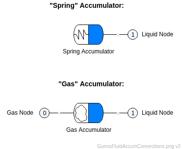
Port Connection Rules (These are limitations on the port connection to nodes that the link enforces in run-time):
- Port 0 (the spring side) must always connect to the network Ground/Vacuum node. This is an optional port in GunnsDraw, and GunnsDraw automatically connects it to Ground when the port is omitted.
- Port 1 (the blue side) must always connect to a non-Ground node containing liquid.
Other Rules (These are extra rules you should always try to follow):
- Never attach other capacitive links, tanks or accumulators to either node.
- Use the GunnsFluidAccumGas instead of this link when you want to model the effect of gas pressurizing the liquid, either in direct contact with the liquid or through the bellows barrier.
- You should always have an accumulator wherever there is flexible volume in the modeled system. Real-world liquid systems are engineered to include flex to prevent trapped liquid bursting pipes, etc. Likewise, if you provide no place for expanding liquid to go, it can blow up your network -- analogous to bursting pipes.
Configuration Data Parameters:
- maxConductivity (default = 0 m2, must >= 0): This models the opening through which liquid flows in and out of the accumulator's liquid volume, just like a GunnsFluidConductor. A higher conductivity allows faster flow in and out of the accumulator, but too high a value can make the model unstable. You should tune this to correspond to the real orifice area -- see the GunnsFluidConductor notes on tuning.
- minConductivityScale (default = 0, must be (DBL_EPSILON-1), recommend 0.1): When the accumulator reaches completely full or empty of liquid, it becomes a rigid tank that can no longer receive flow in that direction, so the link isolates itself from the rest of the liquid-side network. The isolation happens gradually when the accumulator quantity is inside a deadband of the full/empty limit. This adds stability and creates a smooth transition to the point where the conductance is closed off completely. The conductivity becomes completely closed off (zero) when the bellows is at a limit (0 or 1). In this condition, if the pressure is keeping the bellows at the limit, then the conductance remains forced to zero to keep the accumulator isolated from the liquid-side network. When the pressure condition reverses such that the bellows will be forced off of the limit, the conductivity is cracked open to allow flow. This minConductivityScale term is used to accomplish this. It is the fraction of maxConductivity that the accumulator's conductance is cracked to. Too small of a value can make the resumed flow too slow, while too large a value can cause instability in the network.
- accumVolume (default = 0 m3, must be (FLT_EPSILON-1)): This is the maximum liquid volume contained in the accumulator when the bellows is 100% full. This should include a small amount of "unusable" liquid volume trapped in the accumulator between the bellows and the exit opening when the bellows is completely empty (0% full). That unusable trapped volume is given by minChamberVolPercent below.
- minChamberVolPercent (default = 0 %, must be > 0 and <= 50, recommend 5-10): This is the percentage of the liquid accumVolume that is trapped in the accumulator when the bellows is completely empty and can no longer flow out. All real-world accumulators have some unusable volume, and this also promotes stability in the model.
- minChamberVolDeadBandPercent (default = 0 %, must be > minChamberVolPercent and <= 50, recommend 10-15): This defines the deadband range described above - it is the percentage of full below which the accumulator starts to gradually isolate itself from the liquid-side network as it is emptying, for stability. The same deadband range is applied when approaching full, i.e. at 100 minus this value. Lower values causes the gradual isolation effect to be more sudden when approaching the limits and too low a value can cause instability in the network.
- forceBellowsMaxRate (default = 0 1/s, must be > 0, recommend 0.016): This sets the maximum rate at which the bellows can move when the user overrides the bellows position via edits & malfunctions, etc. Too small a value can make overrides take too long, while too large a value can cause model instability.
- editHoldTime (default = 0 s, must be >= 0, recommend 5.0): When the bellows reaches the user-edited position, this term defines how long the bellows is forced to remain at that position before the edit is turned off. This allows time for the network to become stable at the edited position. Too small a value can cause a quick jump from the edit position when the edit completes.
- minTemperature (default = 0 K, must be >= 0, recommend liquid freezing point): This sets the lower limit on the liquid temperature in the accumulator. This is a safety limit to prevent run-away thermal conditions from blowing up the network.
- maxTemperature (default = 0 K, must be > minTemperature, recommend < liquid boiling point): This sets the upper limit on the liquid temperature in the accumulator. This is a safety limit to prevent run-away thermal conditions from blowing up the network.
- maxPressure (default = 0 kPa, must be >= DBL_EPSILON, recommend > max operating pressure): This sets the upper limit on the liquid pressure in the accumulator. This is a safety limit to prevent run-away conditions from blowing up the network.
- The following parameters define the bellows pressure curve. This is a 2nd-order
polynomial of pressure (kPa) as a function of fractional bellows position (0-1). This allows you
to combine many effects into a total pressure exerted on the liquid, such as bellows stiffness,
external spring constant, neutral point, external weights, piston force, gravity, etc:
- springCoeff0 (default = 0 kPa): The 0th-order coefficient to the polynomial. A non-zero value here combined with zeroes in the other two coefficients causes the accumulator to always control its pressure to this value when it is not completely empty or full. An example of this use would be in a system that uses constant weights on the bellows, etc.
- springCoeff1 (default = 0): The 1st-order coefficient to the polynomial. This is the slope of the pressure vs. bellows position. Effects such as spring constants and gravity/acceleration show up in this term.
- springCoeff2 (default = 0): The 2nd-order coefficient to the polynomial. This can be used to exhibit non-linearity in the bellows pressure, such as stiffening of the bellows at certain points, etc.
Input Data Parameters:
- malfBlockageFlag (default = false): Initial state of the blockage malfunction activation flag. NOTE: the blockage malfunction is deliberately not implemented in this link and has no effect.
- malfBlockageValue (default = 0.0, must be (0-1)): Initial state of the blockage malfunction value.
- initialBellowsPosition (default = 0, must be (0-1)): This is the initial bellows postion and fraction of liquid fill of the accumulator.
- liquidFluidInputData (default = NULL, must != NULL): This defines the initial fluid state of the liquid in the accumulator. Similar to initialFluidState in GunnsFluidCapacitor.
- Pressure & Bellows Position Instability: Minor oscillation in pressure and bellows position is not dire, but can indicate a potentially larger problem. Large and/or diverging oscillations indicate a tuning problem. Such instability is usually the result of the bellows pressure being too sensitive to flows in & out of the accumulator. Pay attention to the recommended tuning values, ranges, and notes on stability for the configuration data parameters above. In addition, the bellows spring polynomial can be reduced to encourage stability.
- Bellows Position Drifts to Limits: Normally the bellows position is always moving slowly due to temperature & density changes in the liquid system. Because the accumulator is the source & sink of all liquid in & out of the system, it responds to almost anything going on in the system -- flows going in or out of the system, leaks, pump speed changes, valve movement, changing heat loads, etc. However if it keeps drifting until it completely fills or empties without any obvious reason why it should, this indicates a setup & tuning problem. Make sure that the accumulator has adequate volume and that the bellows spring polynomial is fit properly to bound the normal operating pressure range of the system between its fully empty & full positions. Make sure temperatures are stable. If temperatures and pressures are correct but the problem still occurs, this indicates mass flow in or out of the system.
- Liquid Pressure or Temperature Drifts to Limits: Like with the bellows position, it is normal for pressure & temperature to move around in a liquid system. Uncontrolled pressures indicate either the bellows spring curve isn't properly tuned, or there is unaccounted for mass leaving or entering the system. Uncontrolled temperatures indicate a heat load imbalance in the system.
- N/A