vB5 Board Stack - alanbjohnston/CubeSatSim GitHub Wiki
These instructions are for the vB5 version of the CubeSatSim. Information on the latest version is here.
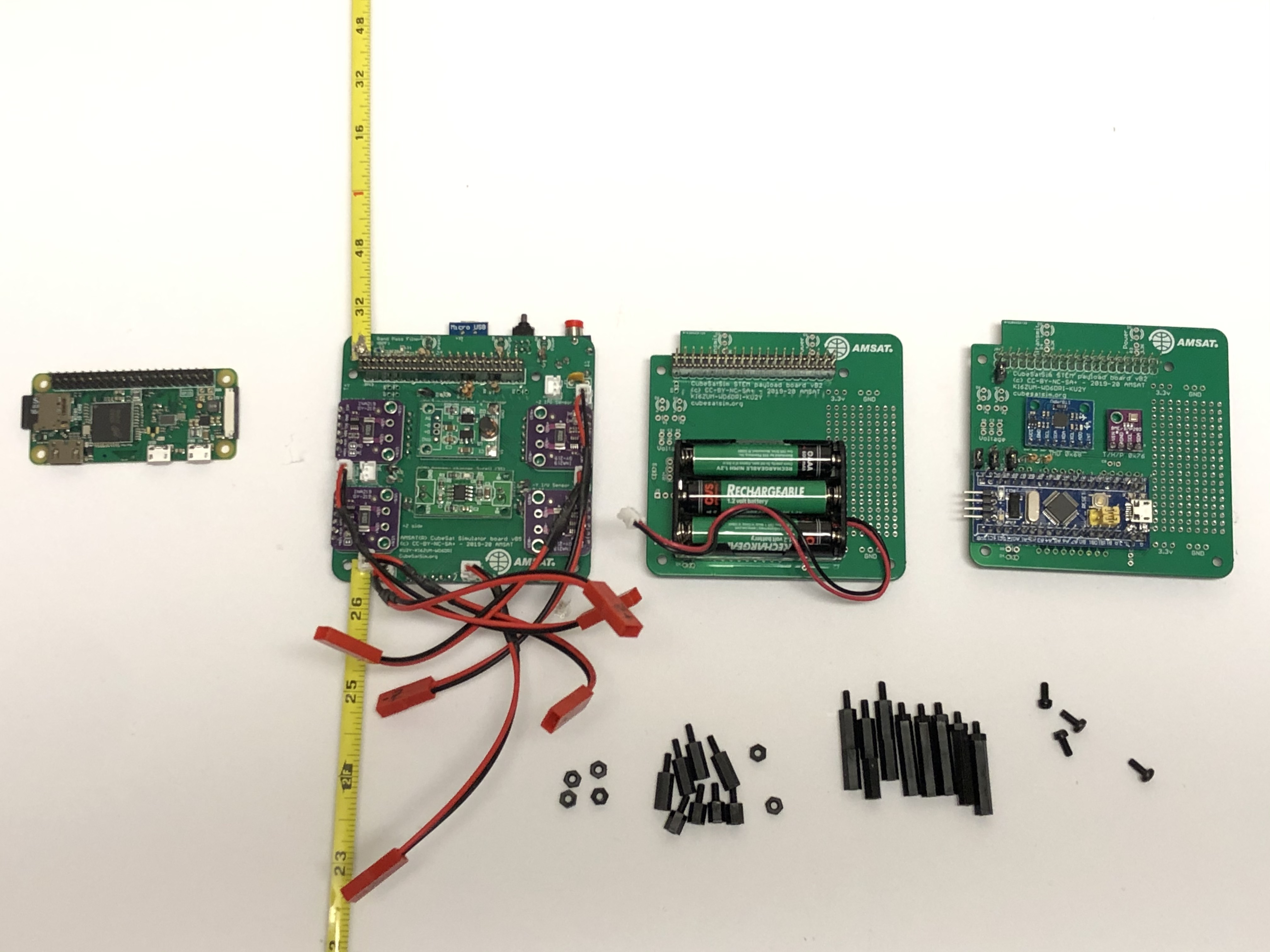
The four boards in the board stack are shown here along with the 2.5mm nylon spacers:
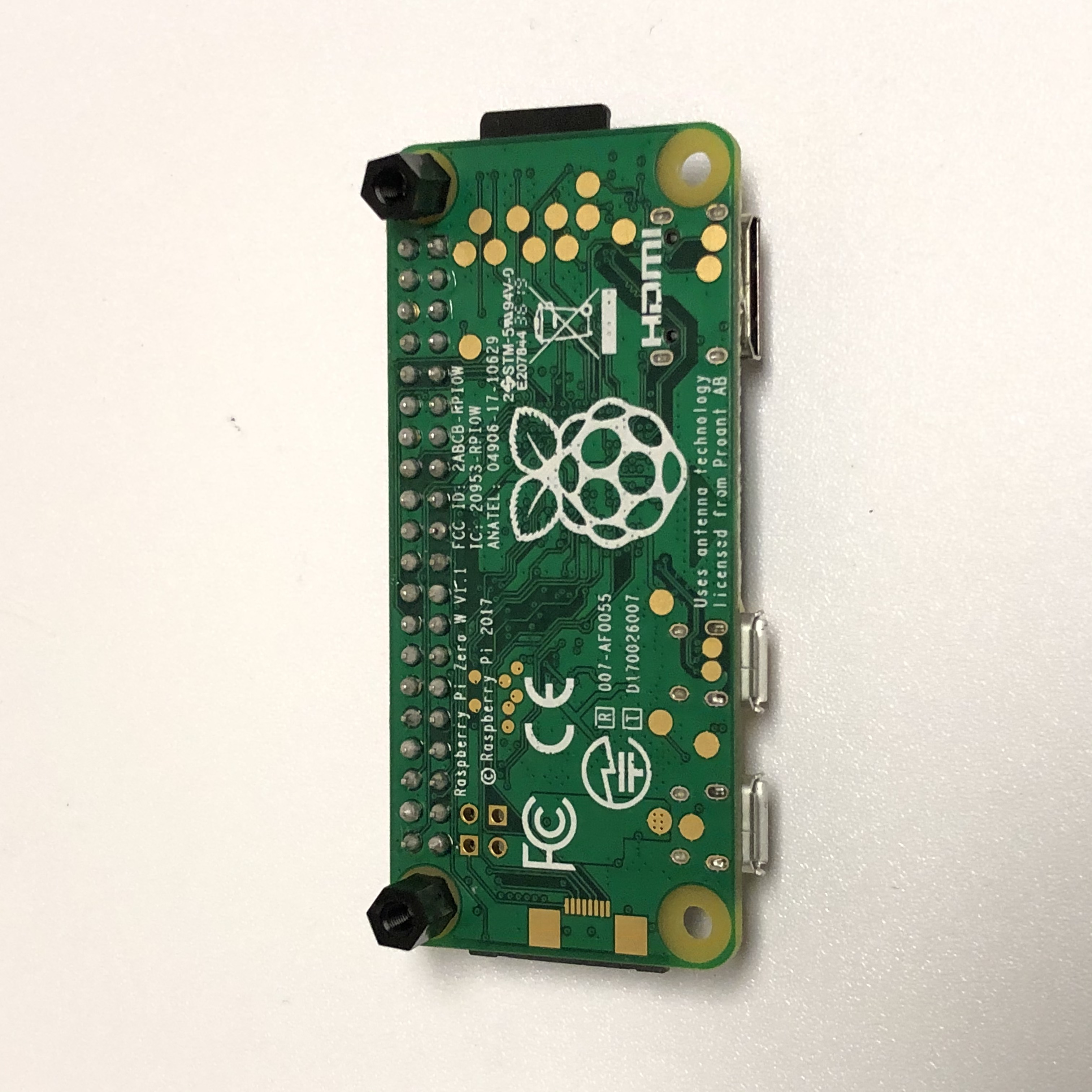
Start by adding spacers to the bottom of the Pi Zero W board next to the GPIO header:
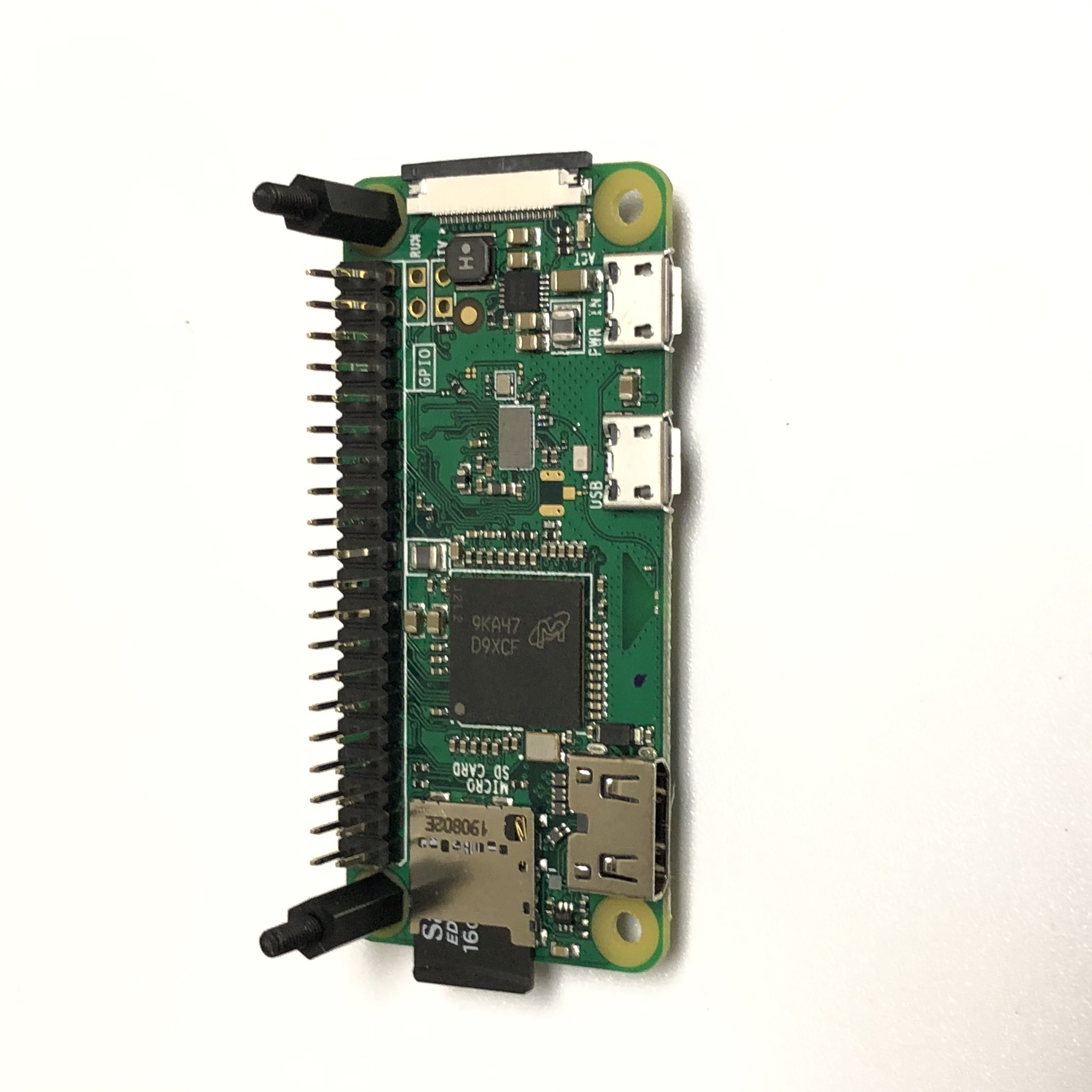
Next, add spacers to the top of the Pi Zero W board next to the GPIO header:
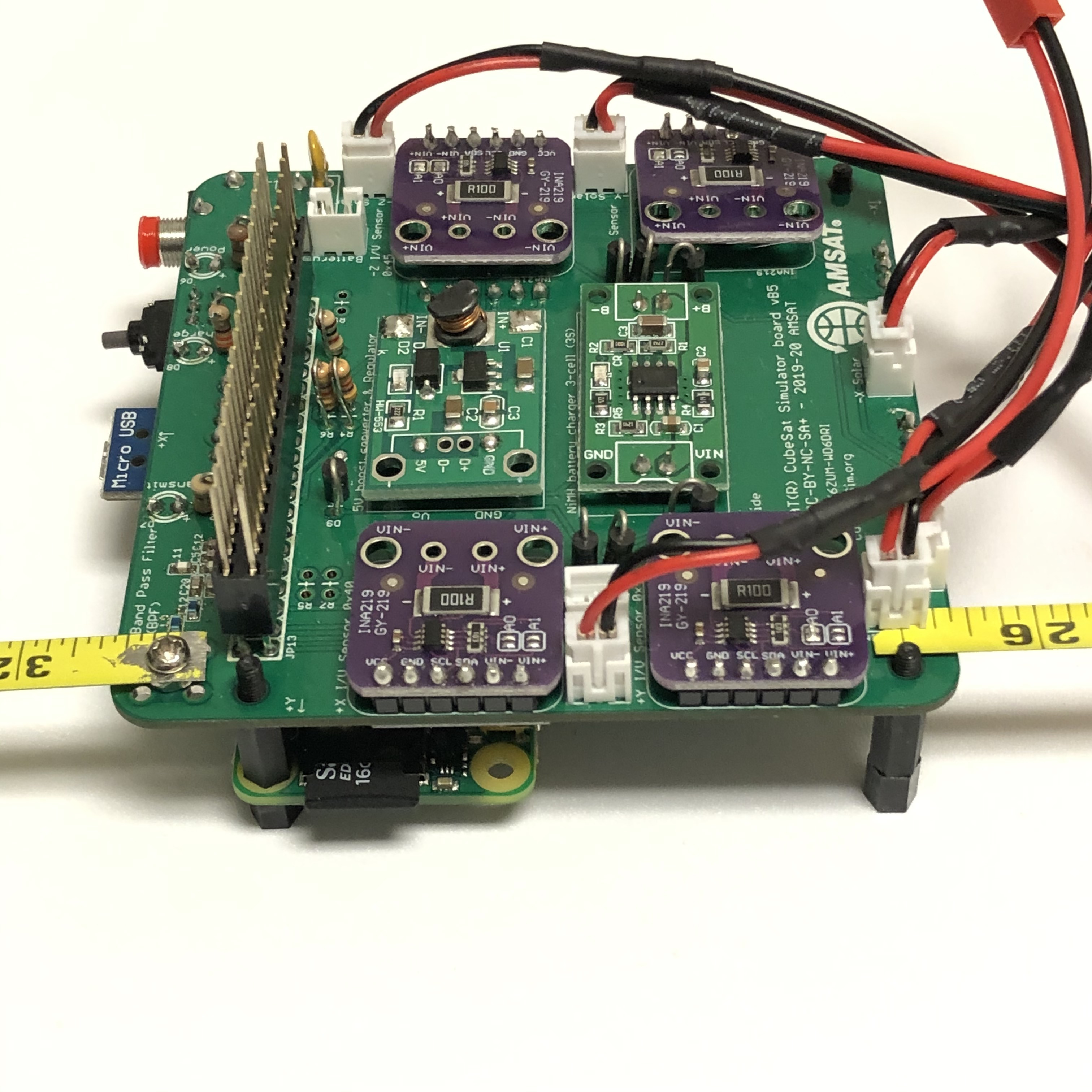
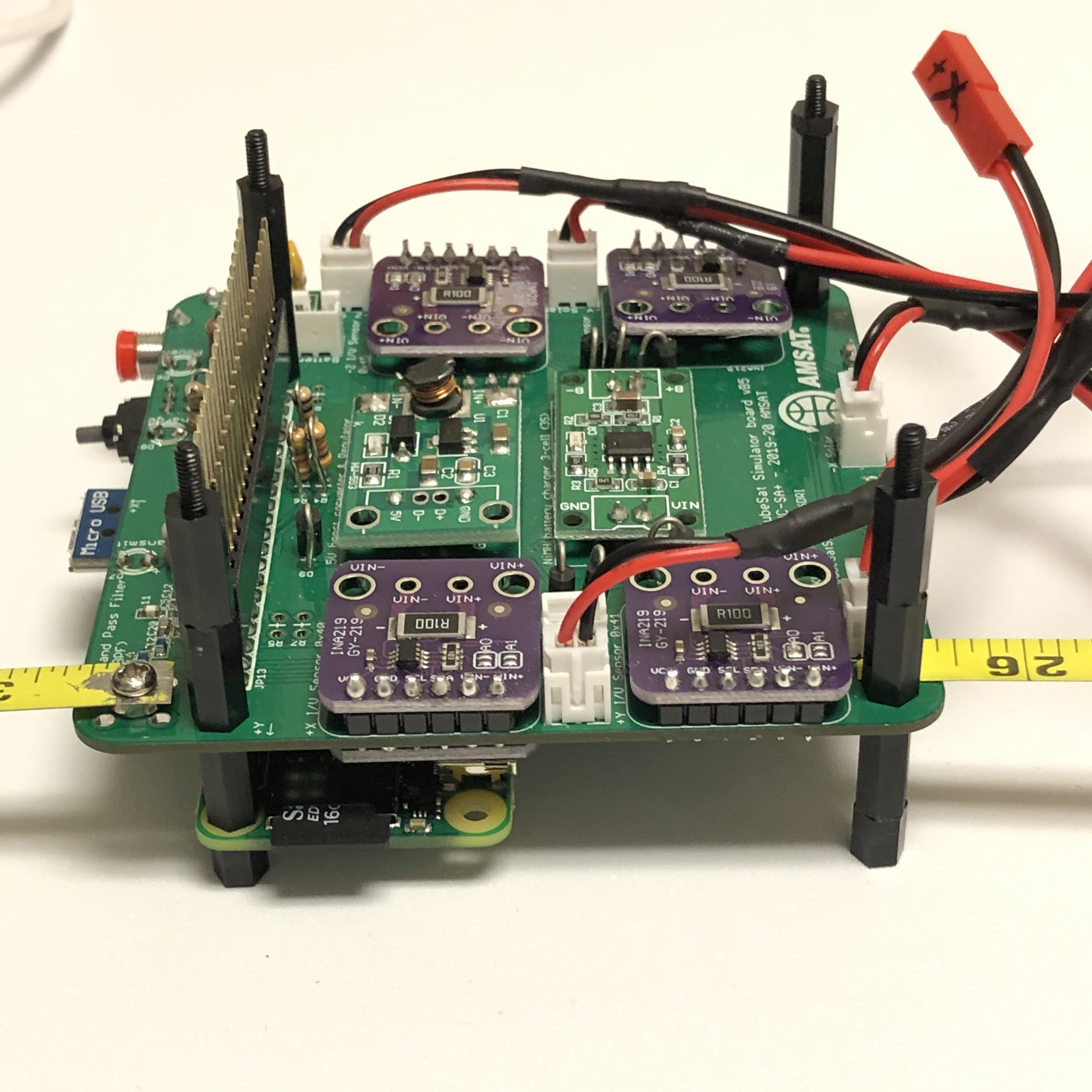
Now, put the Main Board on top of the Pi Zero W while also adding two spacers under the main board:
At this point, you can still plug a Pi power supply micro USB connector directly into your Pi and run the Pi and the Main Board. If, however, you plug the Pi power supply into the Main Board, the Pi will not boot - the board does not run without the batteries connected.
When the Pi powers up, and you have done the software installation, you will hear your Morse Code (CW) callsign then you will hear telemetry radio signals. Note that the pushbutton will not function yet to shutdown or reboot the Pi.
To continue your build, add four spacers on top of the Main Board. Note that an extra stacking GPIO header is used:
Make sure the Remove Before Flight (RBF) pin is inserted and the Pi power supply is not connected directly to the Pi. This will ensure that the Pi will not power up before you are ready. Test the polarity of the Battery Board before plugging it in:
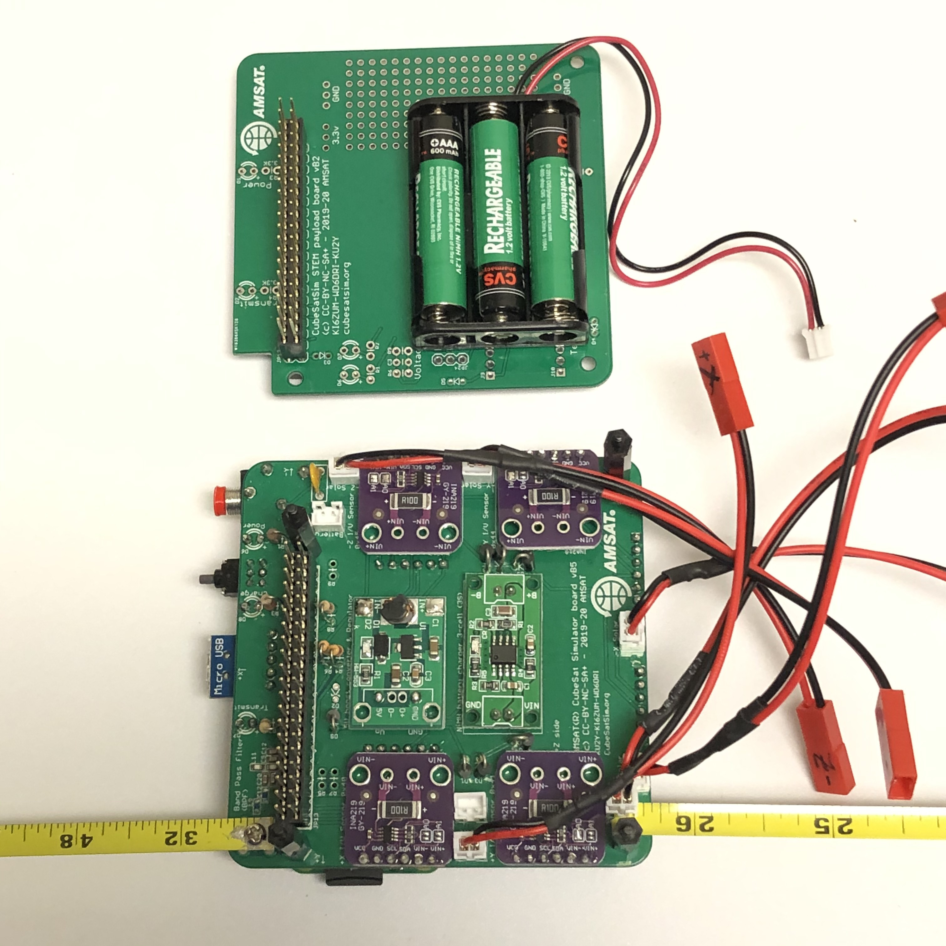
Plug in the JST 2.0 connector from the Battery Board into the Main Board:
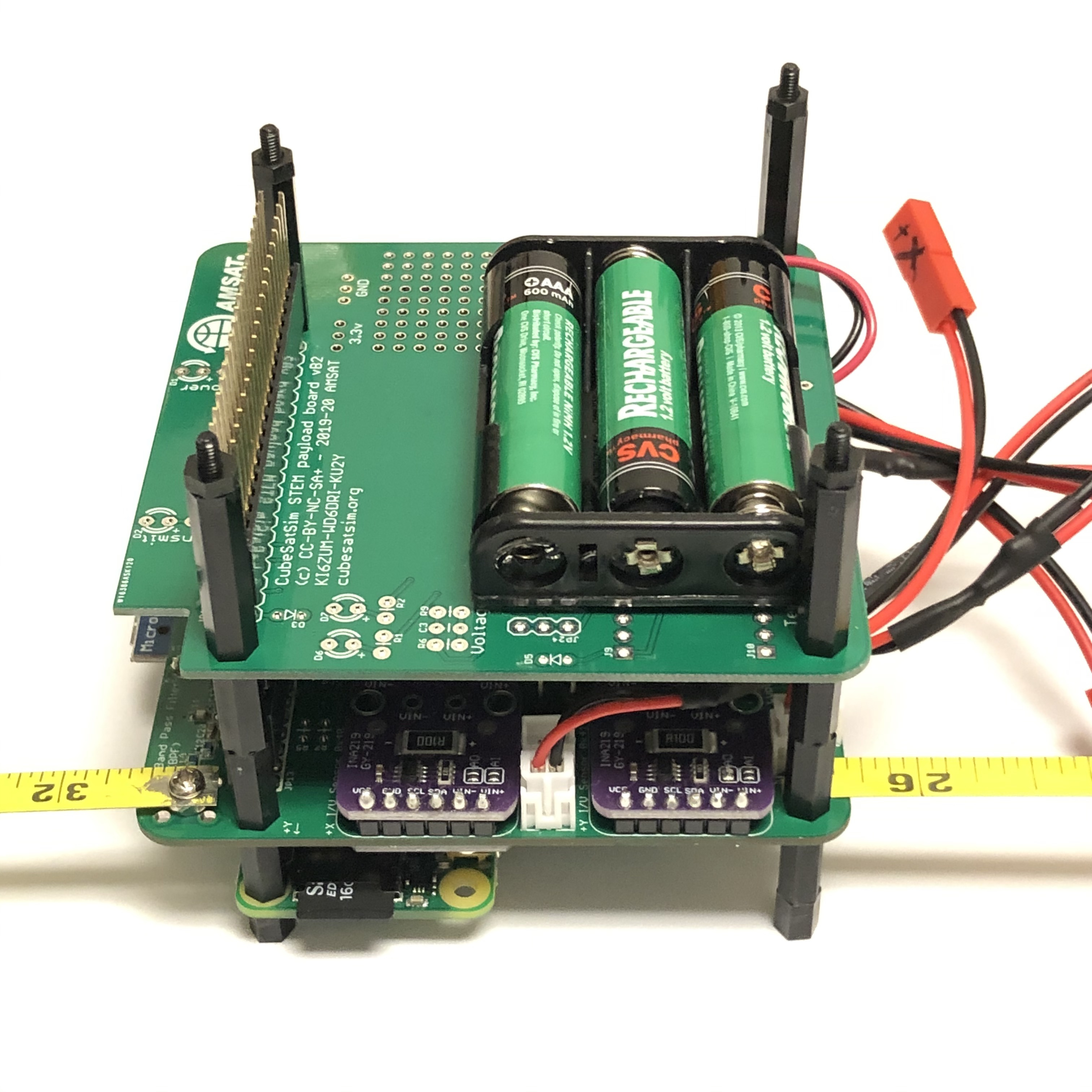
Plug the Battery Board on top of the Main Board:
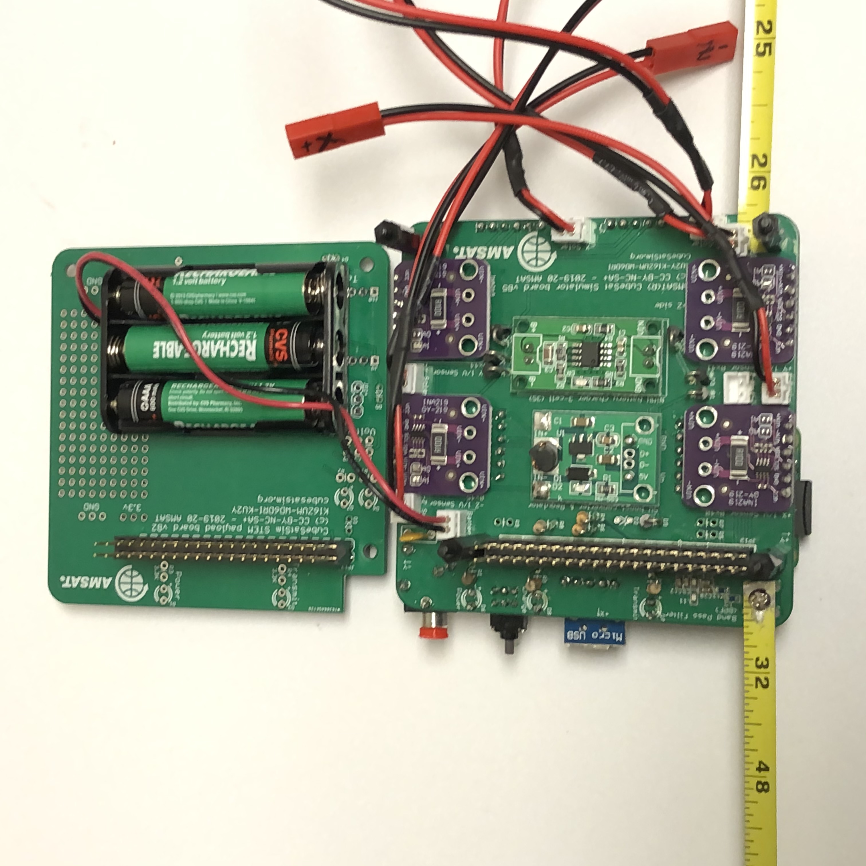
Now that the battery is connected, the Pi power supply micro USB connector should only be plugged into the Main Board. It will charge the battery and also power the CubeSatSim.
You can test the CubeSatSim by removing the RBF pin. Unless the batteries are fully depleted (NiMH batteries normally come charged up), the green light on the Pi will flicker and the CubeSatSim will boot up and start running.
The green LED on the Main Board will be lit up after booting is complete and the software is running. The blue LED on the Main Board will be lit up when the CubeSatSim is transmitting. The red LED on the Main Board will be lit up when the battery is being charged by either the micro USB power supply or by the solar panels.
The pushbutton on the Main Board can now be used to reboot or shutdown the CubeSatSim. Pressing and releasing the pushbutton will cause the green LED to turn out and the Pi to reboot. This will cause the demo.sh script to switch to the other mode (i.e switch from alternating telemetry mode and continuous DUV FSK mode). Pressing and holding the pushbutton for 3 seconds will cause the green LED to flash three times then go out. This will shutdown the Pi. Once it has shutdown, it is safe to plug the RBF pin back in. Pressing the pushbutton with the RBF pin inserted will not turn on the Pi.
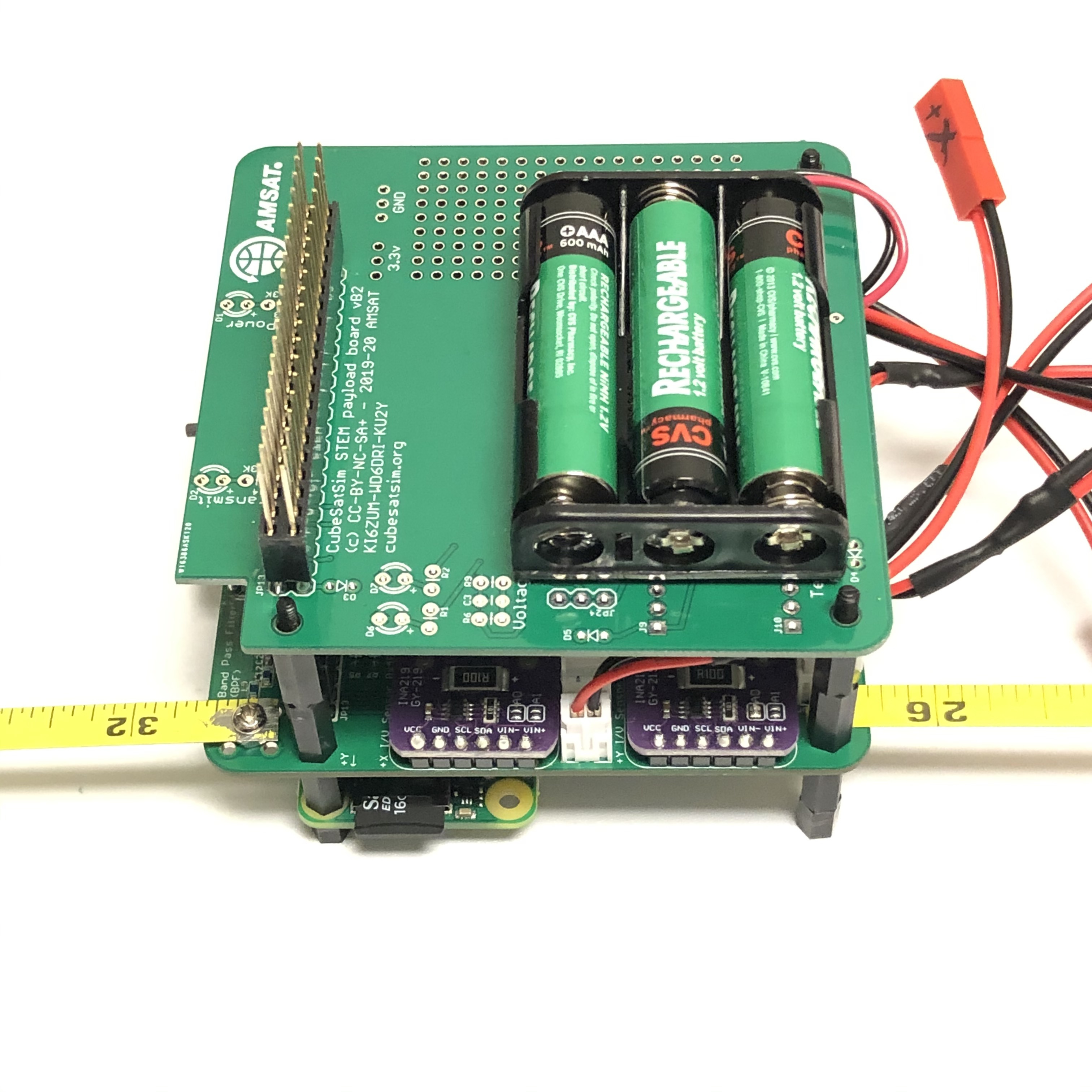
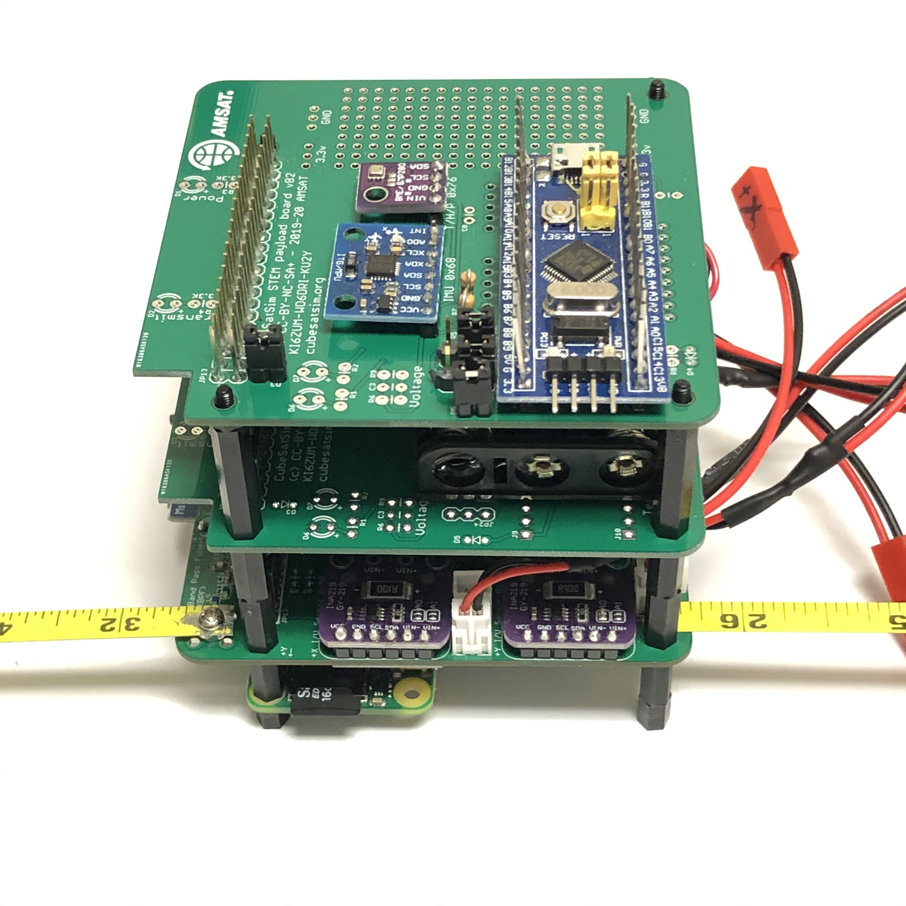
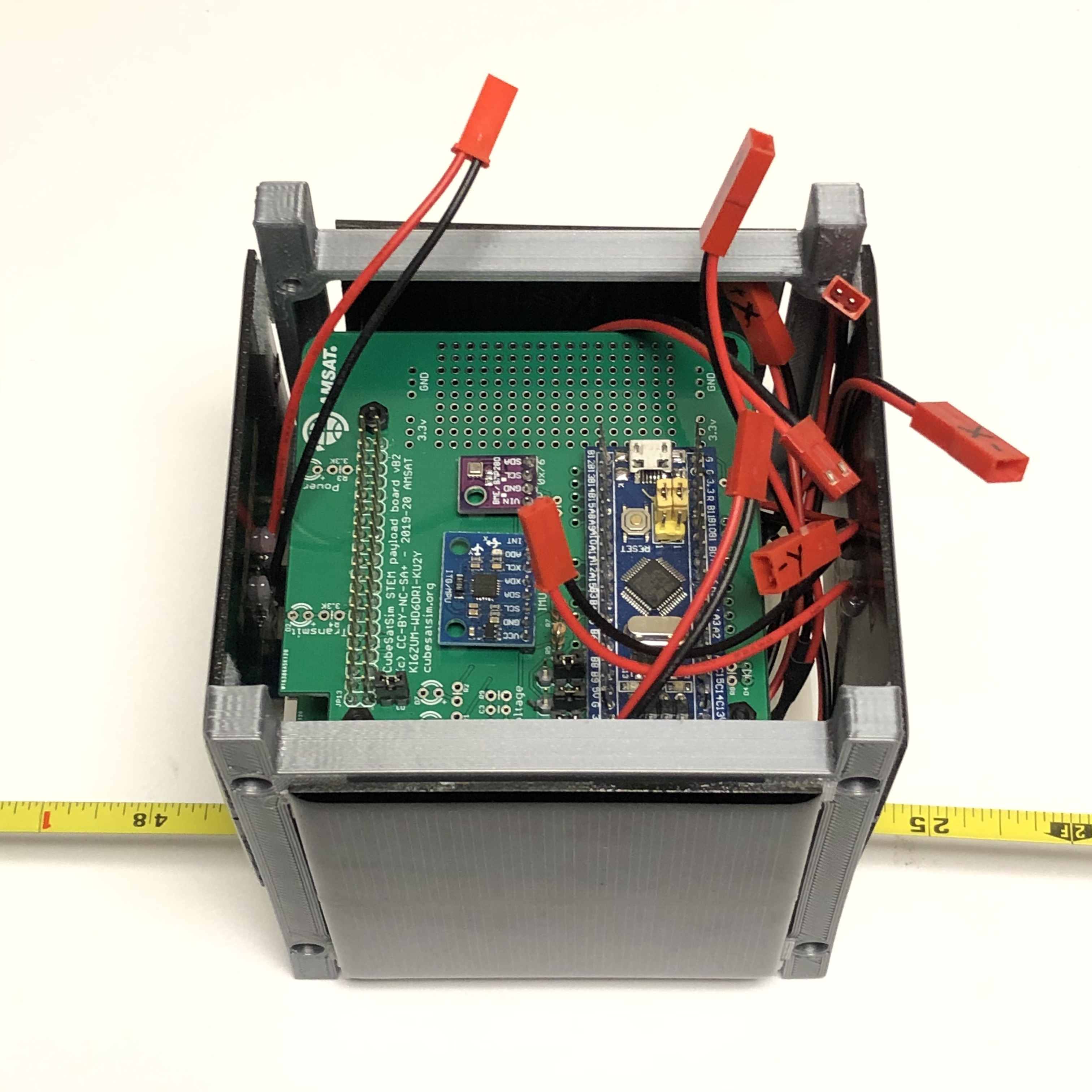
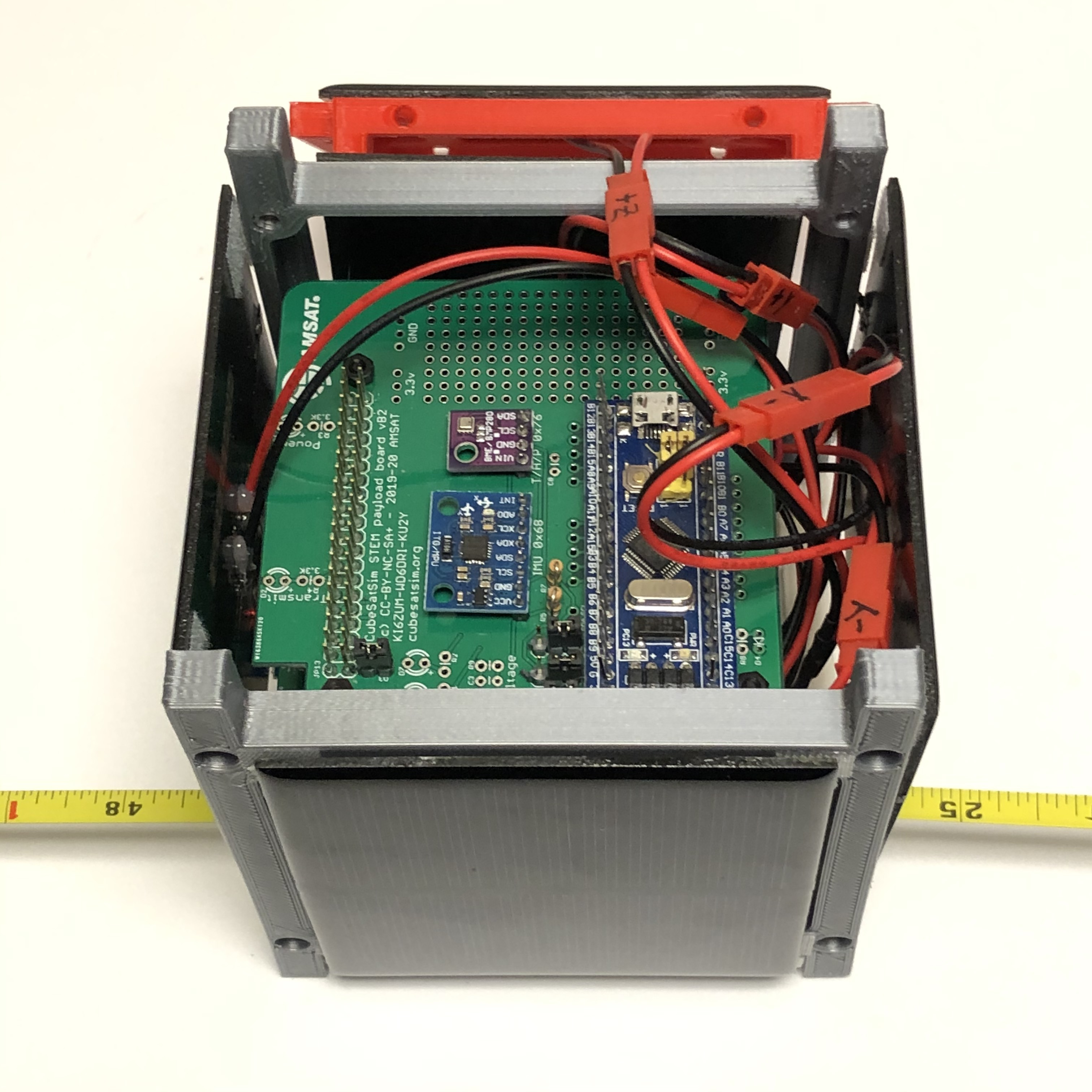
If you have built the STEM Payload Board, then continue your build by adding four spacers on top of the Battery Board. Otherwise, continue to the steps below to insert the board stack into the frame and connect up the solar panels. Note that an extra stacking GPIO header is used:
Plug the STEM Payload Board on top of the Battery Board:
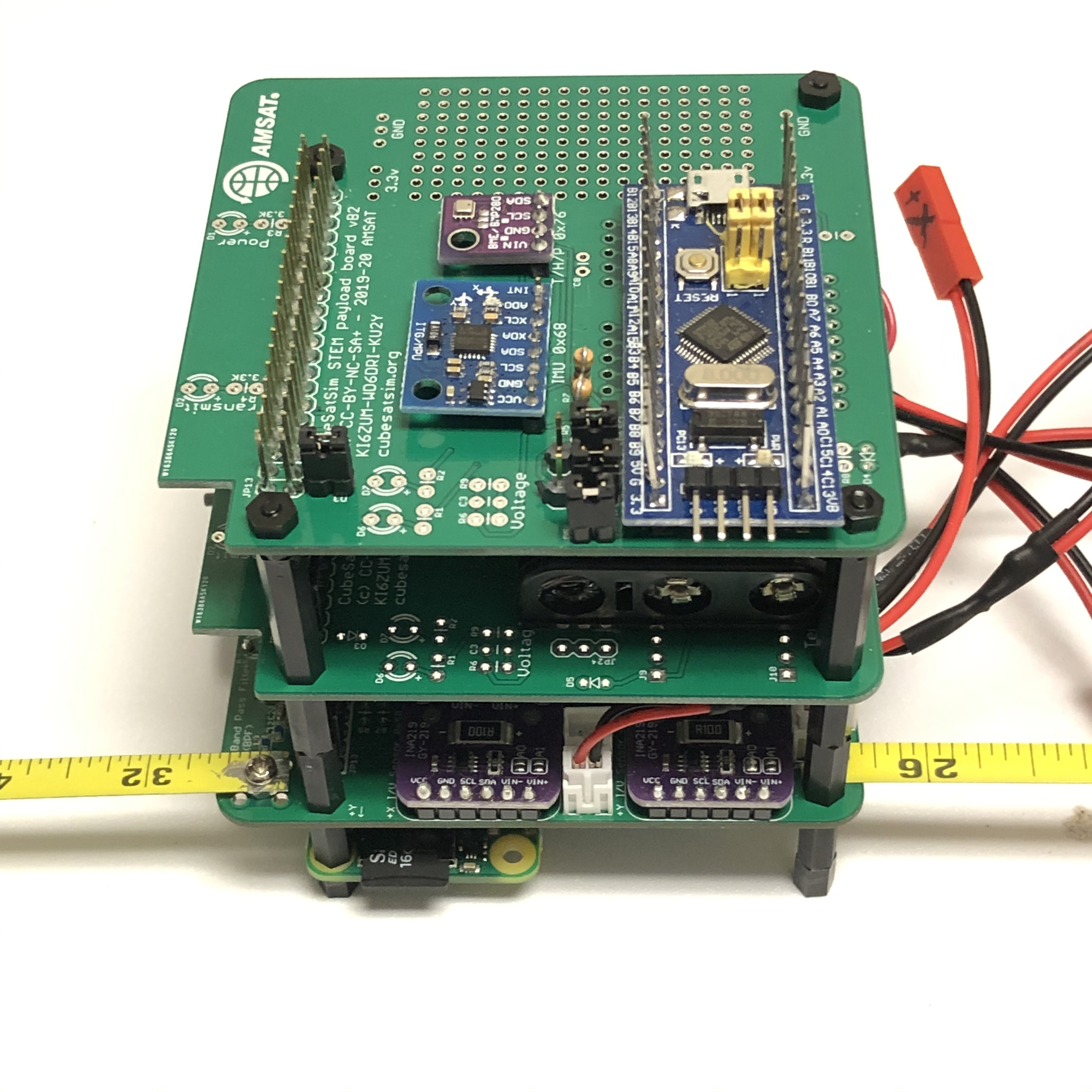
Secure with four nuts:
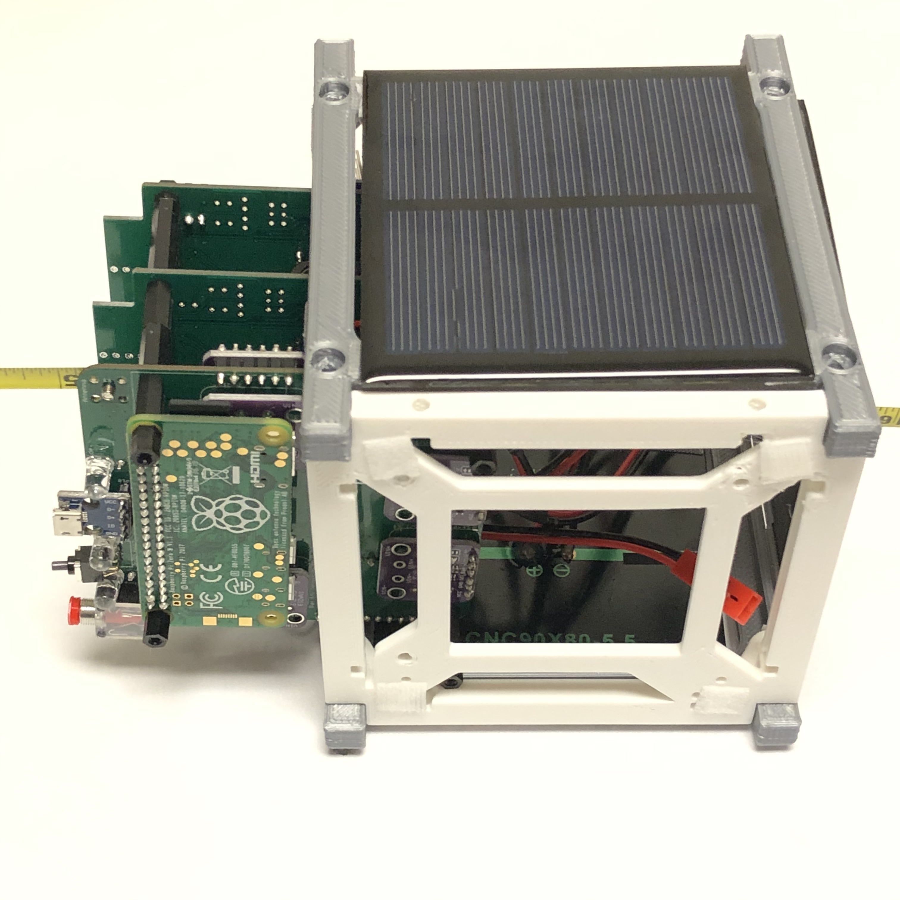
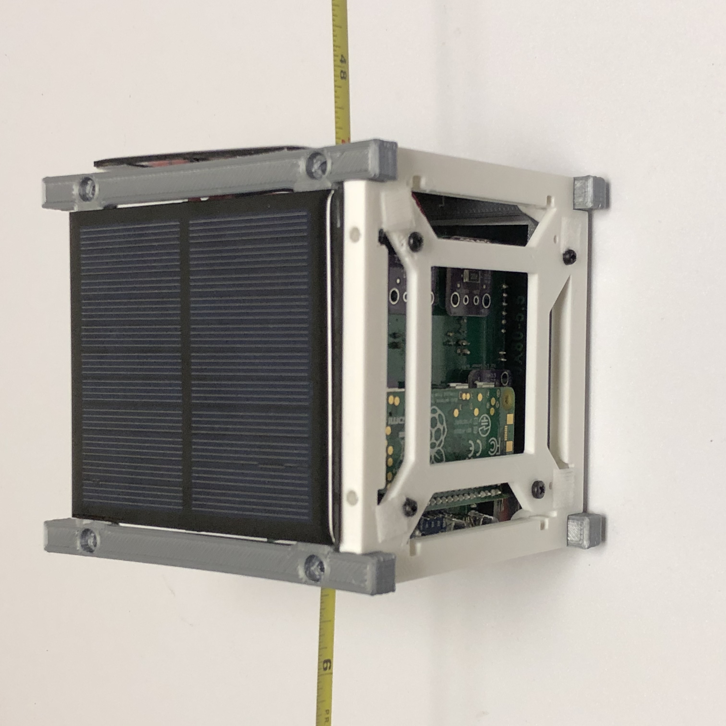
The Board Stack is now ready to go into the Frame. See the Frame page for instructions to build the frame. Slide the Board Stack into the frame:
Secure the bottom of the Board Stack to the Bottom of the frame using four screws:
Connect the -Z solar panel to the right JST JCY connector:
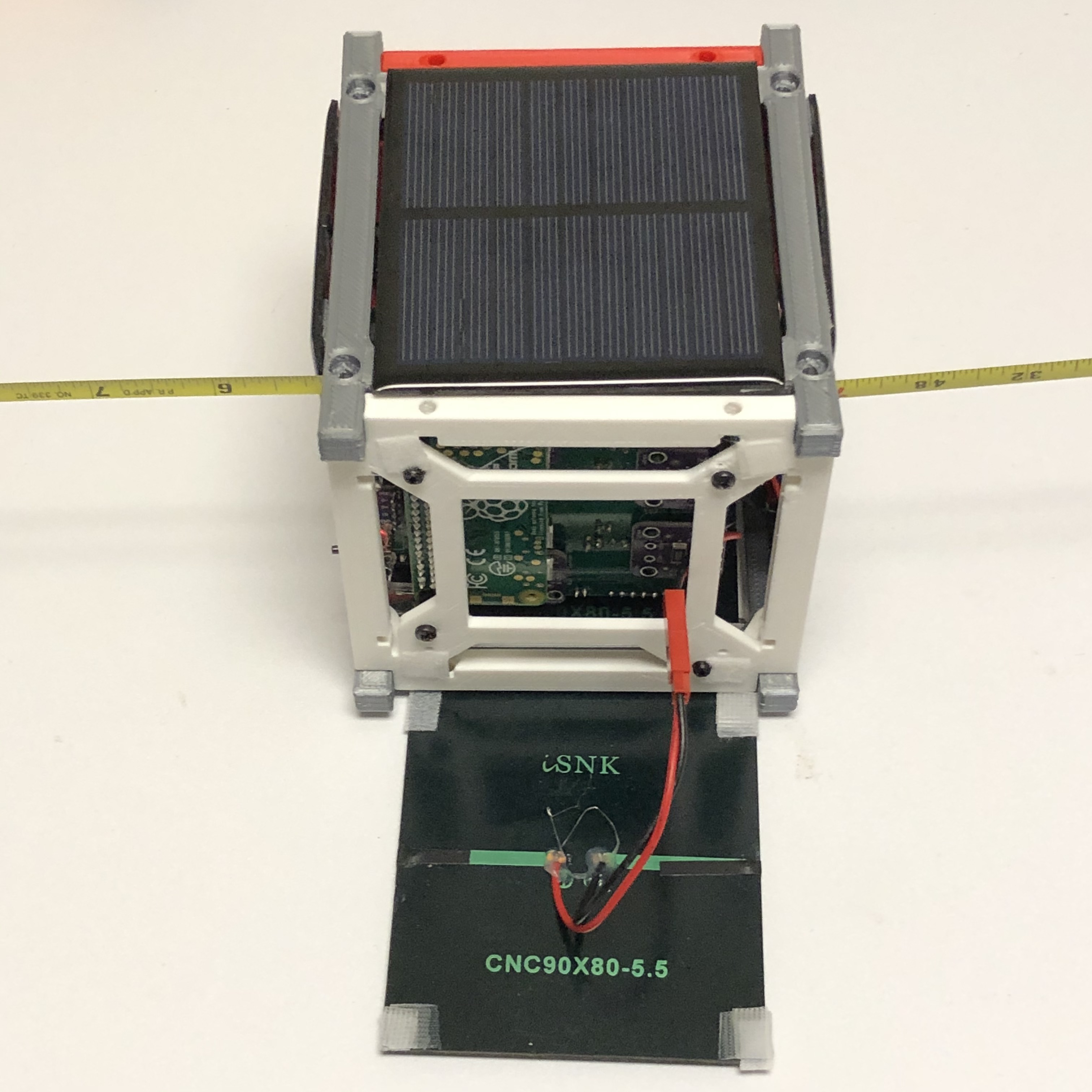
Attach the -Z solar panel:
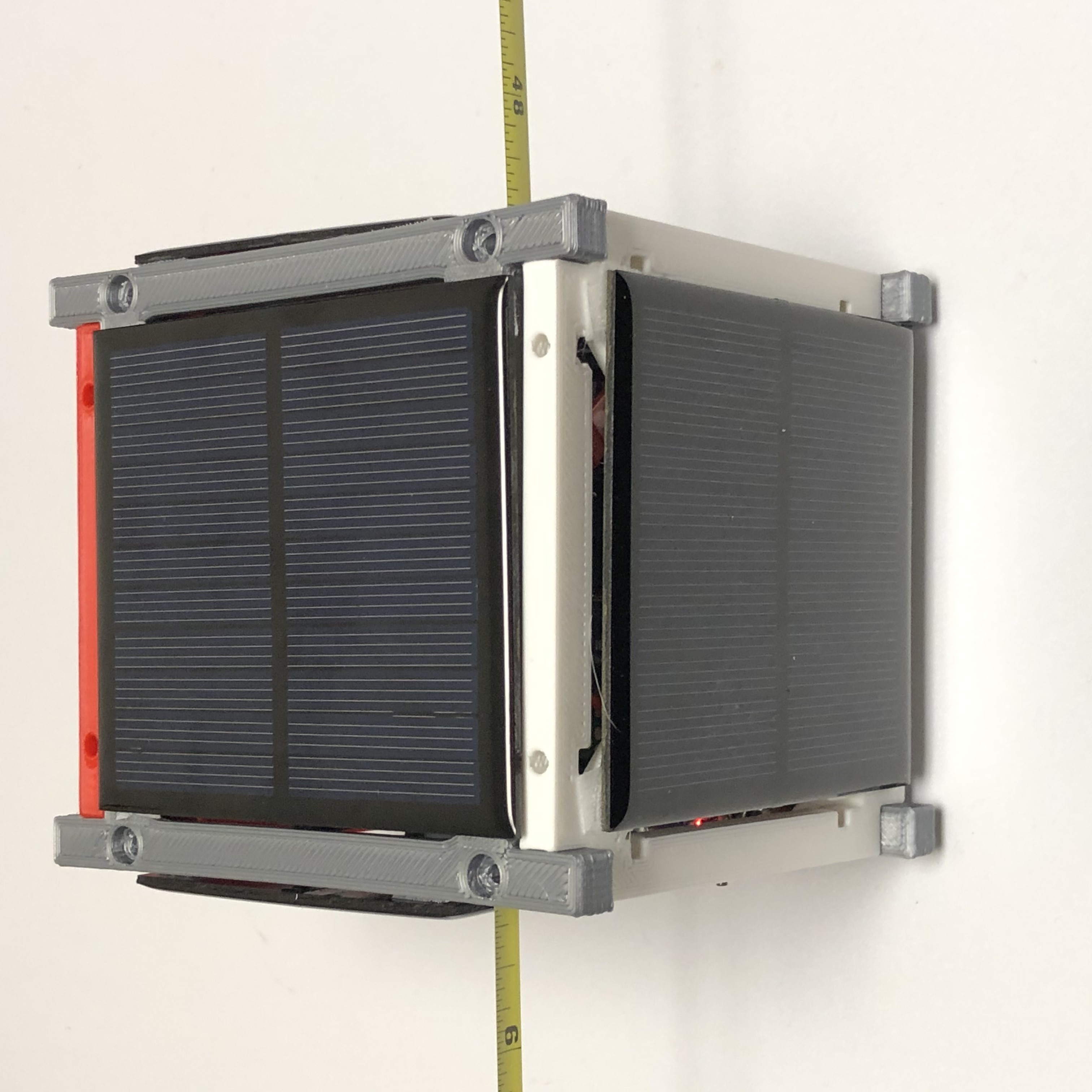
Flip the Frame and Board Stack right side up:
Connect up the solar panels to the correct JST JCY connector:
Put the top of the Frame on:
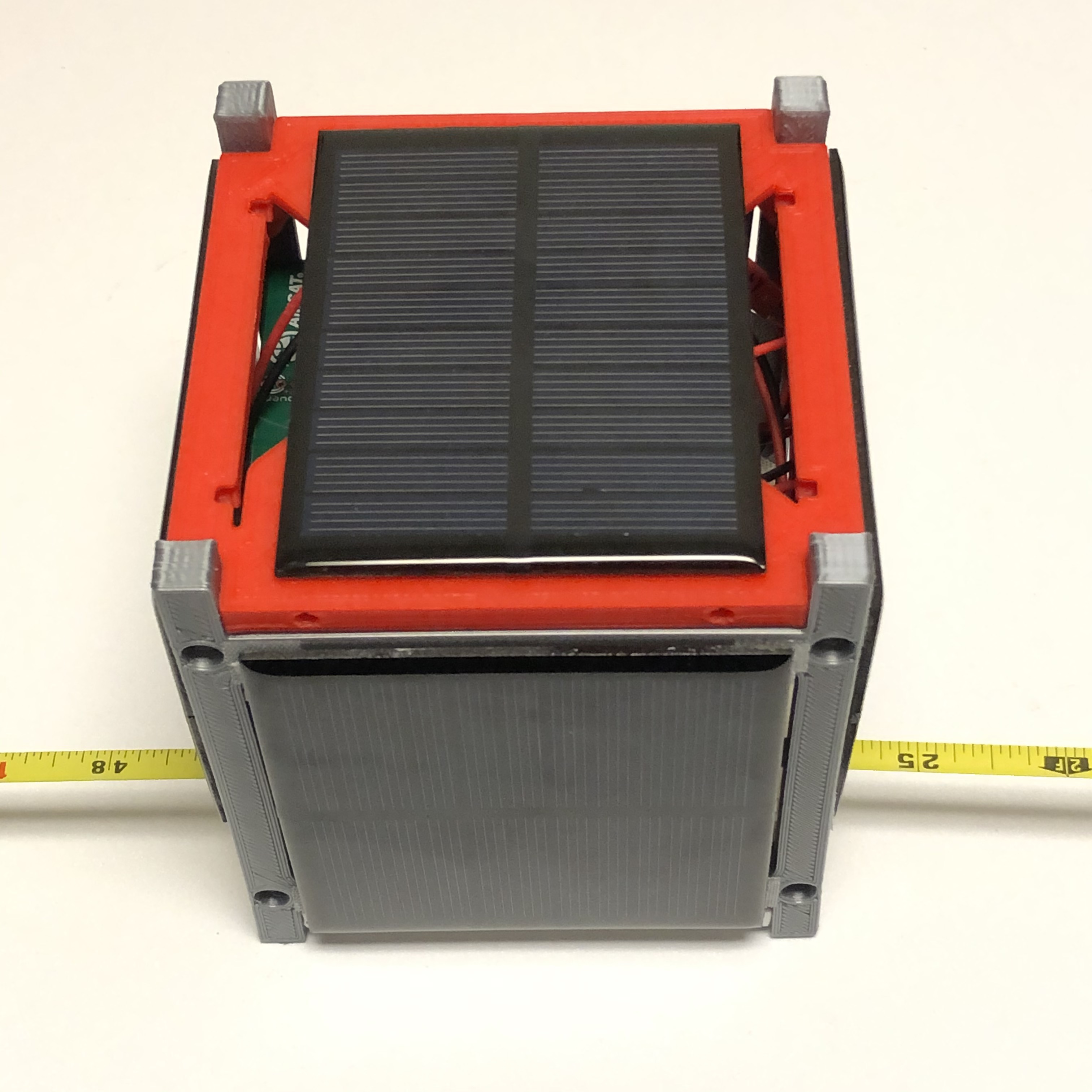
The Board Stack is now complete!