vB5 Arduino Payload - alanbjohnston/CubeSatSim GitHub Wiki
The STEM Payload Board uses a STM32F103C8T6 microcontroller, also known as a "blue pill" due to the shape and color. The next version of the STEM Payload Board will also support the Sparkfun Pro Micro board as well. The Sparkfun Pro Micro board is Arduino compatible and does not need to be flashed, making it a simpler alternative to the "blue pill". The "black pill" board will also be supported in the future.
These instructions cover building the board and flashing and programming the STM32.
Building the STEM Payload Board
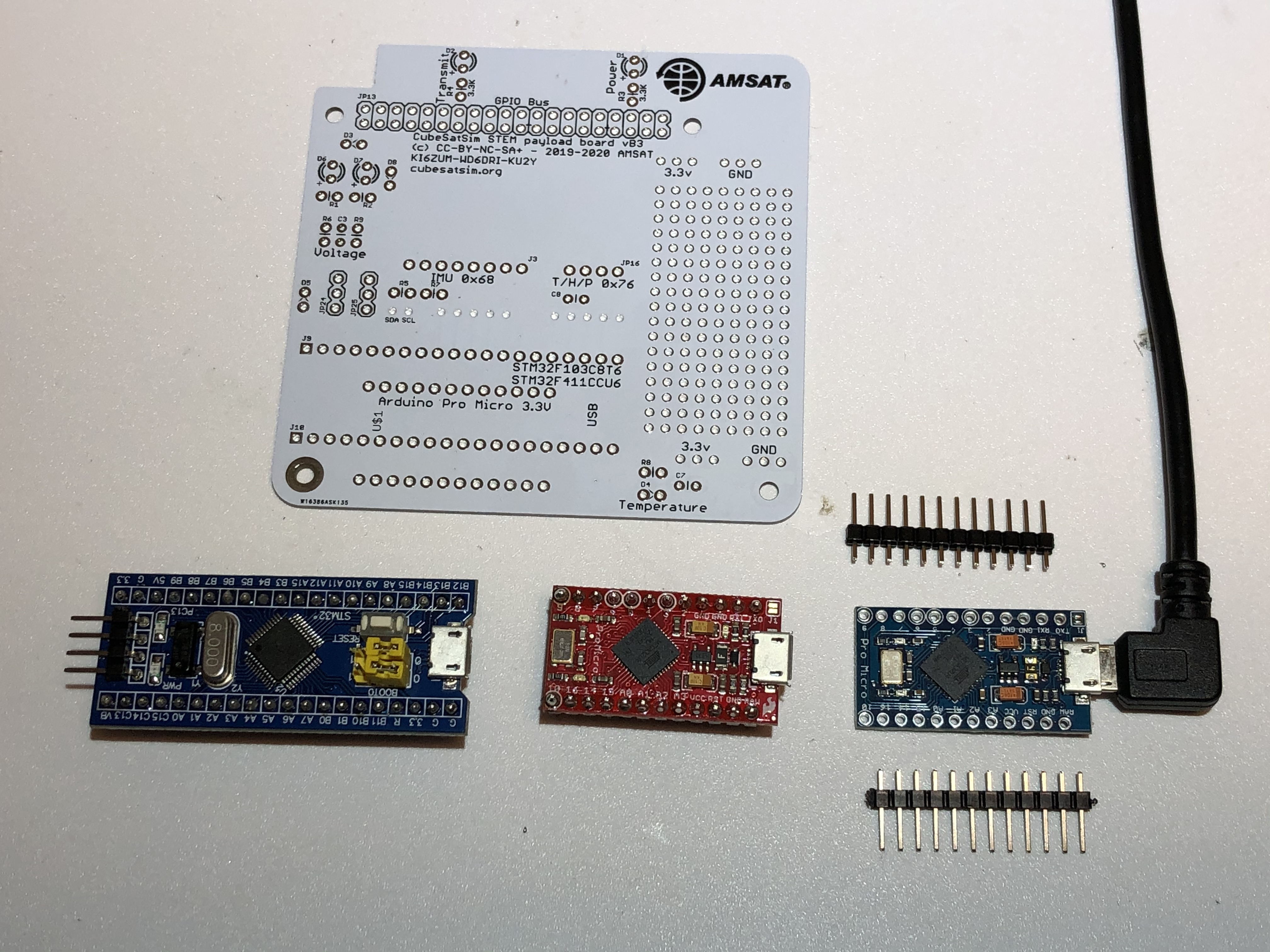
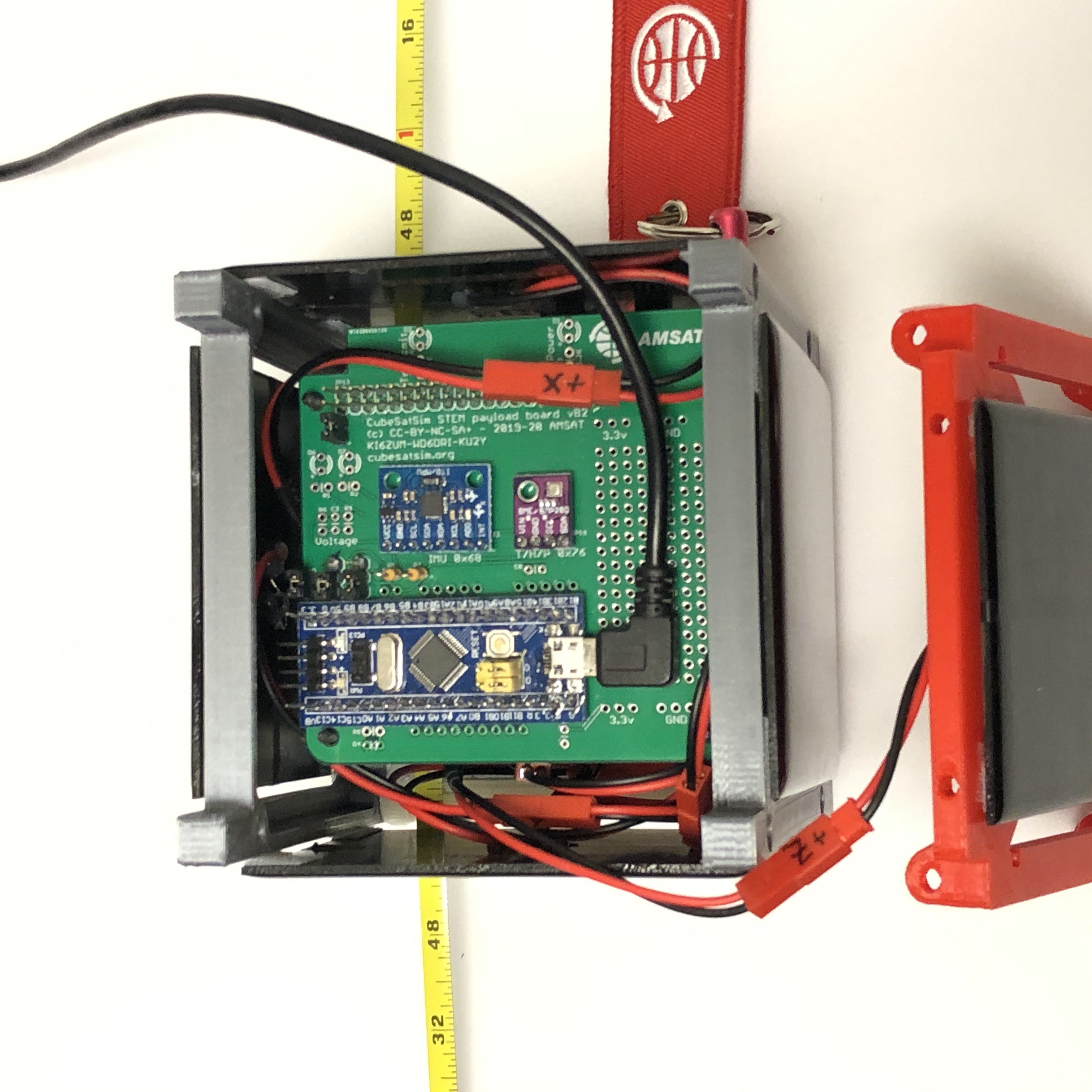
This is the STEM Payload PCB Board along with the STM32 "blue pill" and the SparkFun Pro Micro board (the original red board and blue clone is shown).
I strongly recommend testing and programming your STM32 or Pro Micro BEFORE building the board. Otherwise, if you have problems, you won't know if it is a hardware or software issue.
Test your STM32 or Pro Micro using the Blink.ino sketch to verify that you can program your board. When you have completed that, you can start building the board.
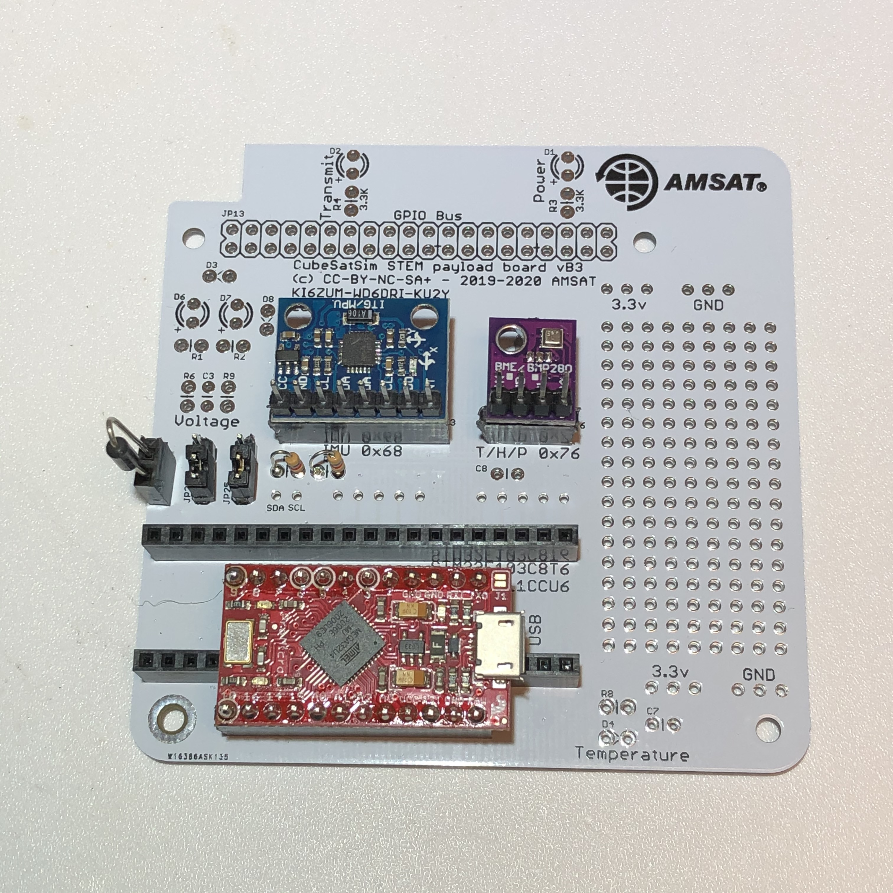
I recommend using female headers so that you can plug and unplug your STM32 or Pro Micro. If you don't plan on using both the STM32 and Pro Micro, then you don't need to install both female headers as shown here with a Pro Micro plugged in:
The minimal components are:
- STM32F103C8T6 microcontroller mounted with two breakaway headers (included in the STM32 package usually). Note that the micro USB connector should not face the edge of the board.
- Diodes D3 and D5 to supply power to the STM32
- JP24 and JP25 jumpers made with two 1x3 male pin headers and two jumpers. The jumpers should be set closest to the STM32 to allow the STM32 to read the sensors. To allow the Pi to read the sensors, set the jumpers in the other position.
- 4.7k Resistors R5 and R7 as pullups for the I2C bus
- BME-280 Temperature Humidity Barometric Pressure Sensor
- MPU-6050 (GY-521) 3-Axis Accelerometer and Gyro
The additional components can also be added to the board to provide additional sensors.
Before continuing the build, you should verify that the BME-280 and MPU-6050 sensors work using the test sketches. At a minimum, run the i2cscanner.ino sketch to make sure that the two sensors are visible on the I2C bus.
If you have the I2C jumpers in the other position, the sensors will be visible to the Raspberry Pi through the Main Board. You can verify them with this:
pi@cubesatsim:~ $ i2cdetect -y 1
`0 1 2 3 4 5 6 7 8 9 a b c d e f`
00: -- -- -- -- -- -- -- -- -- -- -- -- --
10: -- -- -- -- -- -- -- -- -- -- -- -- -- -- -- --
20: -- -- -- -- -- -- -- -- -- -- -- -- -- -- -- --
30: -- -- -- -- -- -- -- -- -- -- -- -- -- -- -- --
40: 40 41 -- -- 44 45 -- -- -- -- -- -- -- -- -- --
50: -- -- -- -- -- -- -- -- -- -- -- -- -- -- -- --
60: -- -- -- -- -- -- -- -- 68 -- -- -- -- -- -- --
70: -- -- -- -- -- -- 76 --
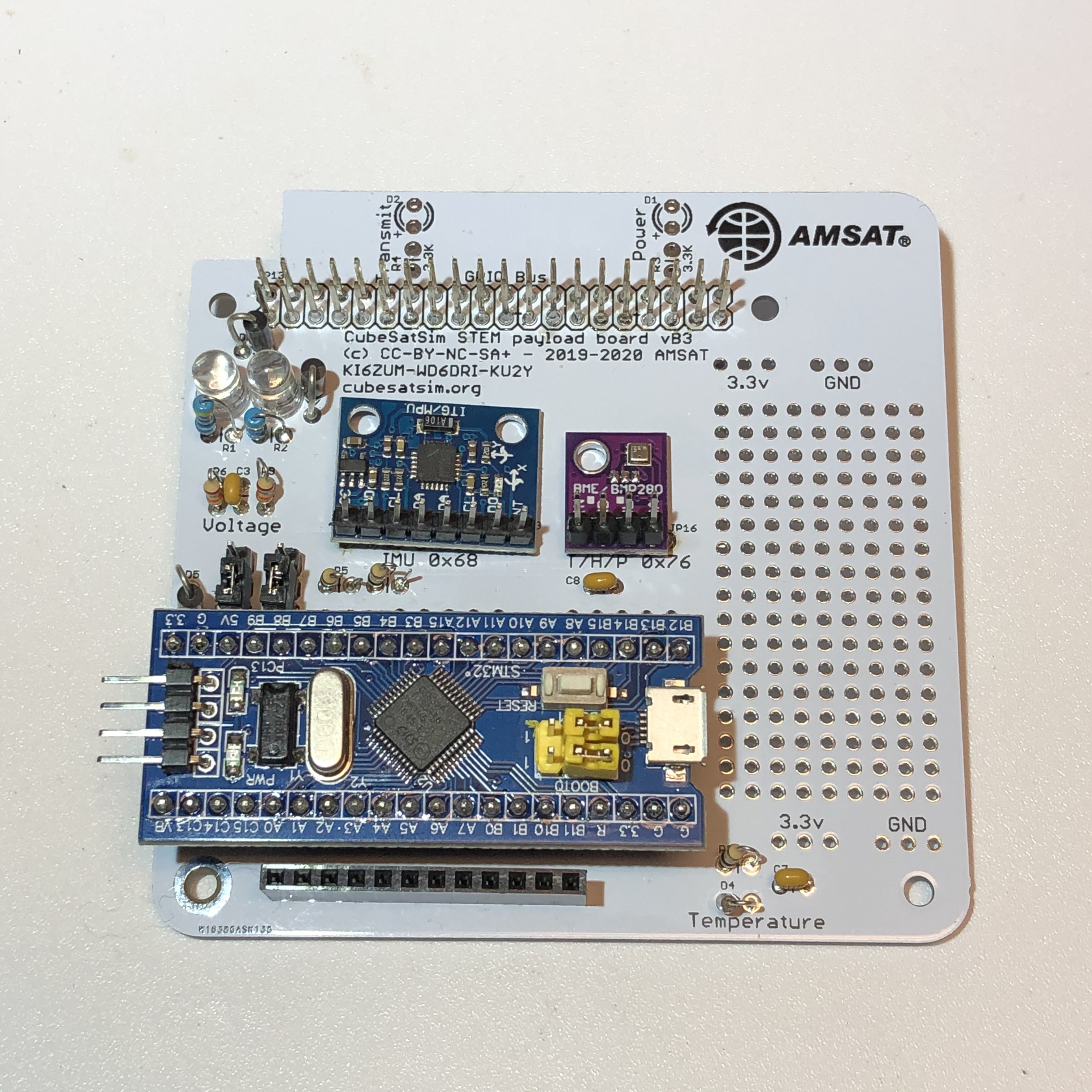
Then, you can complete the build, as shown here:
Flashing the USB Bootloader
These instructions are for configuring the STM32 in the STEM Payload Board so that it can be programmed using the Arduino IDE. Other programming methods and IDEs can be used as well. Before you can program the STM32, you need to flash a bootloader in it so you can push code using the micro USB interface.
This section describes how to flash a USB bootloader into the STM 32.
Follow the instructions https://alselectro.wordpress.com/tag/stm32-usb-upload/ For the Serial USB-TTL adapter, I used the Moyina adapter https://www.amazon.com/gp/product/B075N82CDL/ Some of the lower cost ones just don't work.
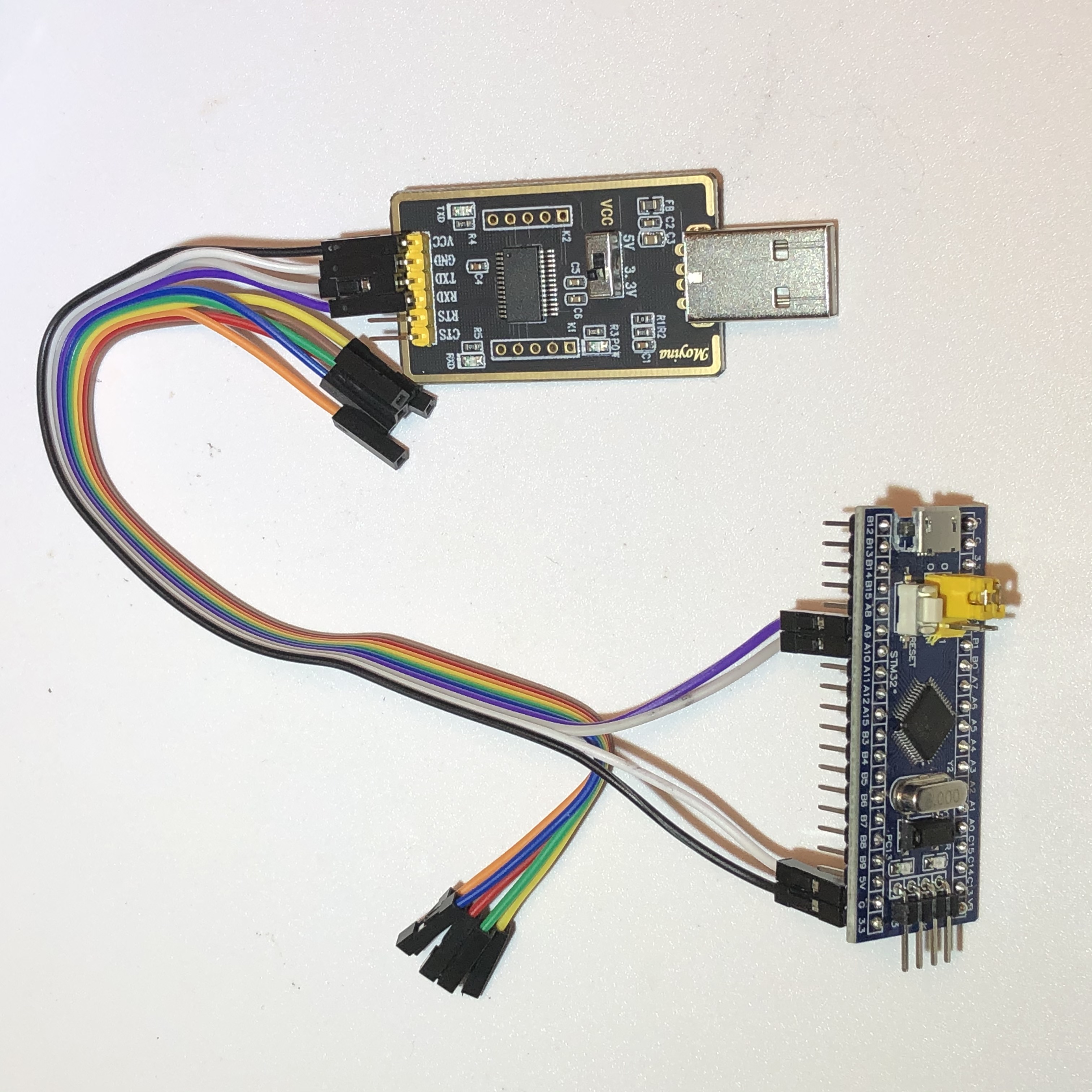
Wired up the STM32 to the USB-TTL adapter set to 3.3V
PA9 Tx to Rx of USB-TTL
PA10 Rx to Tx of USB-TTL
3v3 to 3v3 , GND to GND
This is shown here:
Download the programming tool https://www.st.com/en/development-tools/flasher-stm32.html You will need to sign up and receive email before you get a link to download. Download and install.
Download the firmware generic_boot20_pc13.bin https://github.com/rogerclarkmelbourne/STM32duino-bootloader/raw/master/binaries/generic_boot20_pc13.bin I used this version since the LED on my STM32 board is labeled PC13.
Plug USB-TTL in to USB of computer.
Set jumper Boot 0 to position 1 (closest to edge).
Run flash_loader_demo_v2.8.0.exe to install app in Program Files (x86)/STMicroelectronics/Software STMFlashLoader Demo.exe
Select a Port say Next. Get Target is readable message. Select Next.
2nd option is Download to device/Download from file. Click on the box to get the menu. Change file type to *.bin and select the .bin file downloaded earlier.
Select Next and it will start and you should see a green "Download operation completed successfully" message.
BEFORE YOU UNPLUG ANYTHING, move the jumper back to position 0.
Now, when you plug in the STM32 using the micro USB connector, it will show up as "Maple Mini". If you run the Arduino IDE, select the right port for the STM32 and open the Serial Monitor set to 9600 baud, you will see this message displayed:
Congratulations, you have installed the STM32duino bootloader
See https://github.com/rogerclarkmelbourne/STM32duino-bootloader
For more information about Arduino on STM32
and http://www.stm32duino.com
Arduino Programming IDE
To use the Arduino IDE to program the STM32; plug the STM32 to your computer using a right angle micro USB cable:
Follow the STM32duino installation instructions here:
https://github.com/rogerclarkmelbourne/Arduino_STM32/wiki/Installation
Run the Arduino IDE. The settings under Tools should be:
Board: "Generic STM32F103C series" under STM32F1 Boards (STM32duino.com)
Variant: "STM32F103C8 (20k RAM, 64k Flash)"
CPU Speed(MHz): "72MHz (Normal)"
Upload method: "STM32duino bootloader"
Optimize: "Smallest (default)"
Port: Some COM port here, labeled Maple Mini should be listed
Open Examples/A_STM32_Examples/Digital/Blink and edit LED pin from PB1 to PC13 and compile. You should see blinking! Note that when I use my Mac, I have to reset the STM32 after each push to get it to run the new software.
Payload OK Software
Once you have your STM32 blinking, you are ready to program it with the software that will respond to queries from the CubeSatSim Raspberry Pi.
Download the sketch (code) https://github.com/alanbjohnston/CubeSatSim/tree/master/arduino
Compile it and download to the STM32.
Now, during startup, the CubeSatSim will send a "?" character over the UART and look to get back "OK" from the STM32. If it receives the "OK" then it marks the payload as ON and sets STEMBoardFailure to 0. In FoxTelem, the CubeSatSim-FSK telemetry under Experiments will show "STEM Payload Status" as "OK". If the STEM Payload Board isn't installed or the PayloadOK software not running, it will show as "FAILED".
Testing the Sensors
Here is some code that tests out the two sensors on the STEM Payload Board. Note that we have heard that there are some issues with the latest versions of some of the Adafruit libraries. Some have reported good results with these earlier versions Adafruit BME280 Library version 1.1.0 and Adafruit Unified Sensor version 1.0.3.
The BME-280 Temperature Humidity Barometric Pressure Sensor (small purple board):
https://lastminuteengineers.com/bme280-arduino-tutorial/
The MPU-6050 (GY-521) 3-Axis Accelerometer and Gyro (larger blue board with green LED):