vB2 Software Install - alanbjohnston/CubeSatSim GitHub Wiki
This section covers the installation of the software for the CubeSat Simulator.
This is not the latest version for the CubeSatSim - you can find it here.
There is separate software for each board, so the installation steps are broken down by board.
NOTE: This is for three board stacks built with the Raspberry Pi Digital Transceiver Board using these instructions. For the Transmitter/Filter Board (TFB) three board stack, use these instructions.
Or, you can go back to the CubeSat Simulator Home Page.
This page assumes that you have built the three board stack board.
Software Install Instructions
Raspberry Pi Zero W installation
Note: These instructions are for Raspbian Stretch and Raspbian Buster.
These instructions assume we are starting with a new Raspberry Pi, out of the box. If you are using an existing Pi with software installed, you need to be careful of resource conflicts. This application uses both IC2 buses, the SPI bus, and the UART. Any software that uses them could potentially conflict. Also, the boards used assume a particular GPIO pin mapping, so any software that remaps them could cause failures. Bluetooth must also be disabled (see below).
Start by going through the initial Pi install steps covered here.
https://www.raspberrypi.org/help/
Your Pi will have a username of pi and a default password of raspberry unless you change the password.
If you are using a Raspberry Pi Zero W, then you will most likely need a mini HDMI to HDMI adapter, and a micro USB to USB adapter (USB OTG micro B to A cable) so you can connect a monitor and a keyboard/mouse (to plug both in, you will need a USB hub. There is only one micro USB port on the Pi Zero, and it is next to the mini HDMI connector. The other connector is only for micro USB power input, which we won't use since we will supply the Pi Zero through the GPIO connector. Alternatively, it is possible to switch them, unplugging and plugging as necessary). Also, the Pi Zero W usually comes without the GPIO pins installed. In order to stack all the boards, don't install these pins. Instead, install a stackable header.
Plug a monitor (through HDMI mini adapter) and a mouse (through the USB micro to USB adapter, using the connector closest to the HDMI connector) to the Raspberry Pi Zero W. Make sure a micro SD card (at least 16GB preloaded with NOOBS or Raspbian Stretch or Raspbian Buster) is installed in the Pi.
Then connect the DC power plug to the MoPower board, and the Pi will turn on and boot. A yellow LED on the MoPower board will blink for a few seconds then go out. A red LED will then come on and blink once per second. The green activity light on the Pi Zero W will glow. You can now plug in the NiMH 9V battery (never connect a non rechargeable battery).
On the monitor, after some flashing colors you will see a message saying welcome to Raspberry Pi. You will need to to make some initial configurations using the mouse and keyboard. Click Next to begin. First you will need to Set the Country: select United States, American English, and New York Time Zone then click Next. Next is a Change of Password setting, click Next. Then you can Select a WiFi Network - choose the WiFi name from the list. Now you will need to unplug the mouse and plug in the keyboard to enter the WiFi password. After you click Next, you will have an option to Update Software - this will take a while and when it is finished, you will need to click OK to reboot.
After the reboot, check to see if you are connected to the WiFi and what your IP address is so you can SSH into it. Note that you will need to know the IP address of the Pi in order to connect.
After the reboot, you will either have a login screen (black screen with Username prompt) or the graphical user interface. If you have the graphical user interface, click on the black Terminal icon in the top left of the screen and a black window will open. Click on that window, then unplug the mouse and plug in the keyboard.
After you are logged into your Pi using the keyboard and monitor, you can type:
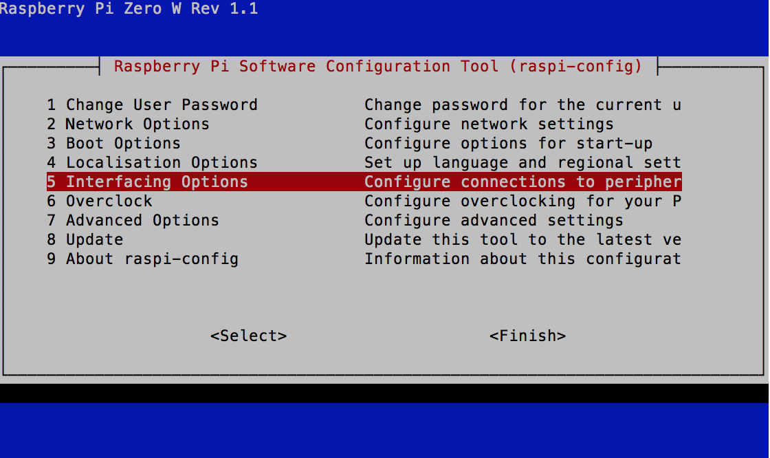
sudo raspi-config
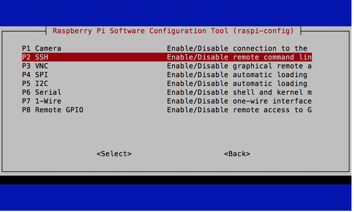
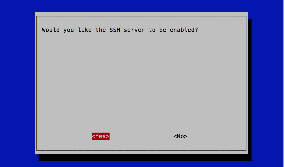
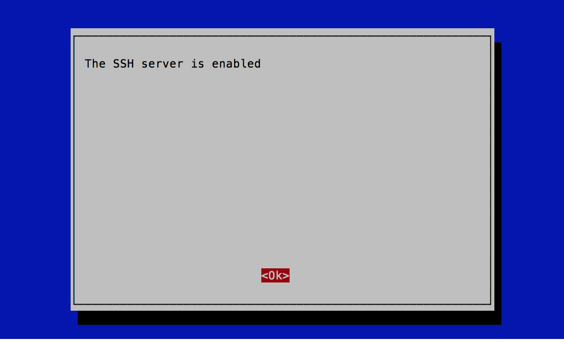
And under Interface Options select SSH then Enable.
Back at the command prompt, type
hostname -I|cut -f1 -d ' '
And look for the IP address displayed (it will probably be 192.168.x.y or 10.1.x.y.z where x, y and z are numbers 0-255.
From now on you don't need to connect the HDMI monitor, mouse and keyboard - you can SSH into the Pi directly. Linux PCs will have a built in SSH client. On Windows, you can install PuTTY. After installation, run PuTTY and for the Host Name or Ip Address put in the IP address that you determined earlier. Leave the port set to the default 22. Click Open to connect and you will be prompted for the username pi and password (whatever you set it to earlier). You can now copy and paste the software installation commands into the window. Note that in PuTTY you use a mouse right click to Paste.
MoPower UPS board installation
To configure the MoPower UPS board, follow the software install instructions from http://www.allspectrum.com/mopower/ which are reproduced here:
cd
wget http://www.allspectrum.com/mopower-hw2/mopower-ups-v0.94-build-07-07-2018.tar
If you get an error saying wget: command not found then you will need to install wget by typing:
sudo apt-get install wget
and typing y when prompted.
tar -xf mopower-ups-v0.94-build-07-07-2018.tar
cd mopower
sudo ./INSTALL-Raspbian.sh
When it prompts You must reboot for the changes to take effect, reboot now? (y/n), type y. Putty will disconnect from the Pi (it may say "inactive" on the window or give you a popup message). You will need to exit Putty and rerun it again, putting in the IP address of your Pi to log back into the Pi, then type:
sudo apt-get -y install python-pip
sudo pip install pi-ina219==1.1.0
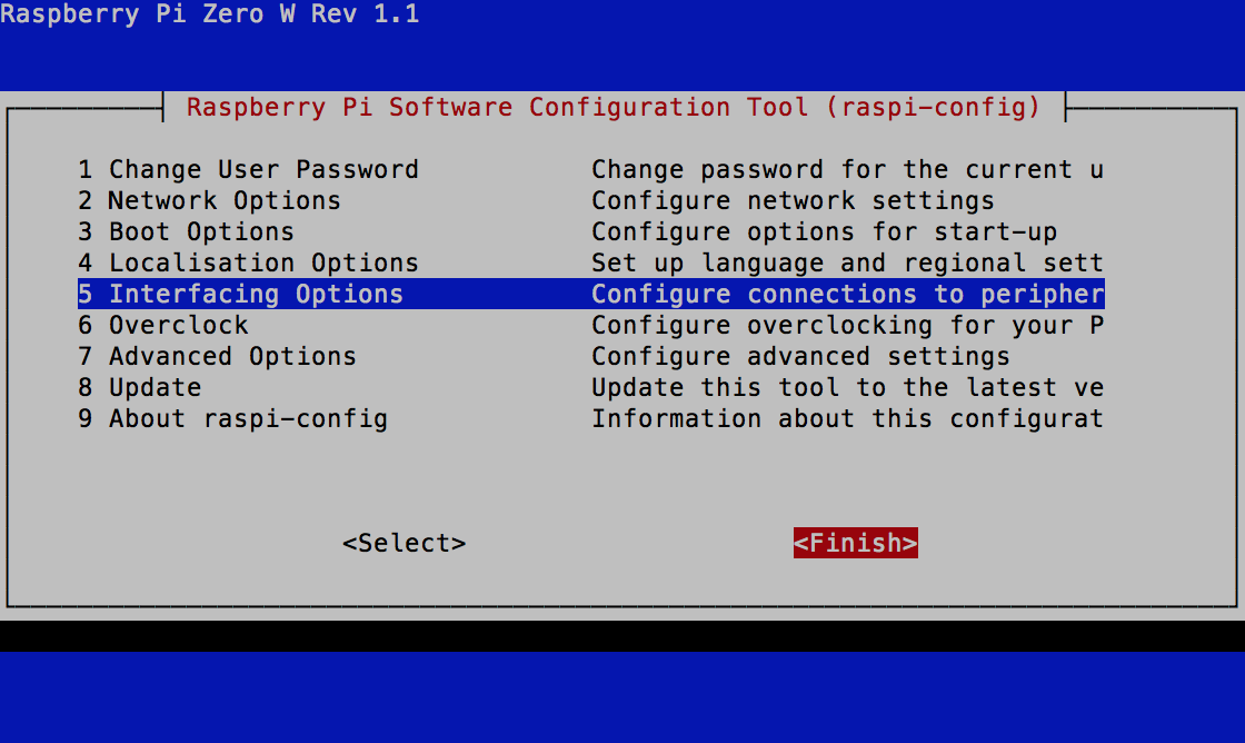
sudo raspi-config
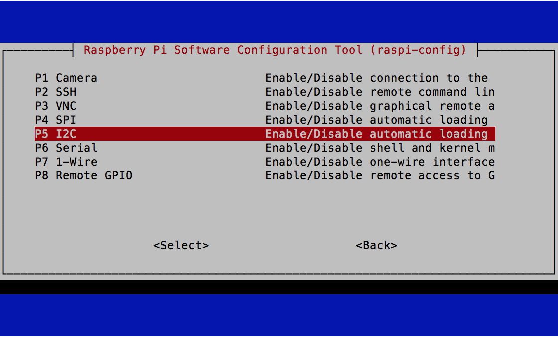
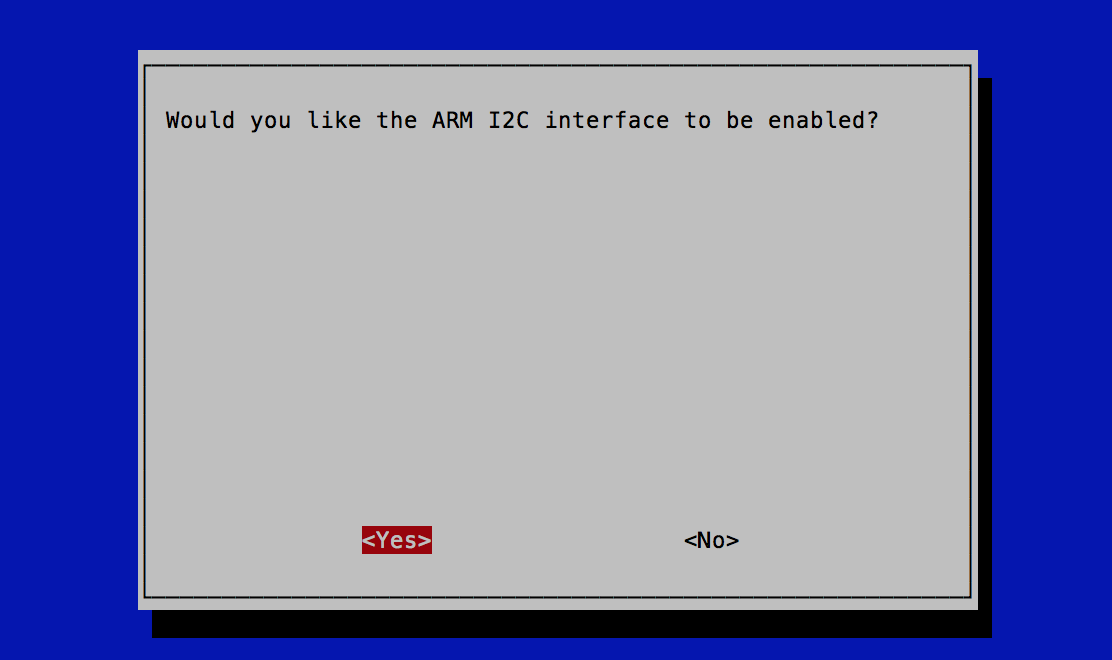
under Interface Options enable I2C.
Reboot by typing:
sudo reboot now
After the reboot, you will need to reconnect using Putty and log back into the Pi. See if the battery logging is working by typing:
sudo cat /run/shm/mopower/mopower-upslog.detail
You should see a series of lines like this:
09/24/2018 18:49:11 09/24/2018 18:49:18 VIN=15.09 VBATT=7.77 5V=5.02/576/2786 UPTIME=1027,0.01 PWR_CMD=0 TMD_SHTDWN=0 CPU_TMP=50.46 CRCPASS=1 SHOW_DATA_OUTPUT=0.934 9 24 2018 18 49 18 2 1027 1 1 0 0 1 15.09 7.77 7.32 0 0 0 0 300 20 0 52 43 60 239 1 1 76 0 0 0 0.000 CRCVALUE=17674 COMPUTEDCRC=17674
With the DC power adapter is plugged in, you will see VIN of about 15 V. If your INA219 current and voltage sensor built into the MoPower board is working, you will see the 5V= line indicating the Raspberry Pi 5V power rail voltage/current (in mA)/power (in mW).
If you have the 9V battery plugged in, you can unplug the DC power adapter and will now be running on the battery alone. The log will show VIN drop to about the same voltage as VBATT, which will gradually get lower as the battery discharges. Plug the DC power adapter back in to save the battery.
To set the charging settings, type:
mpcmd CHARGE_STOP_BVOLTS=9.5
mpcmd CHARGE_START_BVOLTS=9.4
mpcmd SETTINGS_UPS_V_OR=1
mpcmd EEPROM SAVE
This will save these charging settings so they will still be in effect after a reboot. If you want a yellow LED on the MoPower board to blink a message via Morse code, for example, AMSAT or your call sign, type:
mpcmd MORSE=AMSAT
Note that this setting is reset after a reboot.
An experimental battery configuration is to use two 9 V NiMH batteries in parallel. This could be useful for long running demonstrations, to avoid having to swap out batteries frequently. For this configuration, the charging current of the MoPower UPS V2 can be set to 50 mA (by soldering jumpers) and the charging settings would be:
mpcmd CHARGE_STOP_BVOLTS=9.35
mpcmd CHARGE_START_BVOLTS=9.15
mpcmd EEPROM SAVE
Digital Transceiver for the Pi
NOTE: There is a new experimental Transmitter/Filter Board instead of the Digital Transceiver Board. If you are using this, skip the instructions below and follow the steps here.
Next, follow the instructions in https://countingfromzero.net/amsat/getting-started-with-the-digital-transceiver-for-the-raspberry-pi.pdf You don't have to clone the examples archive, but you can if you want to play around with the Digital Transceiver board and write your own code.
The main steps for installing the Digital Transceiver board are listed here:
sudo raspi-config
Make these changes:
• Interfacing Options → SPI – enable
• Interfacing Options → I2C – enable
If asked if you want to reboot, select Yes. After rebooting, log back in and type:
sudo cp /boot/config.txt /bootconfig.txt.0
sudo nano /boot/config.txt
Use the down arrow key to go down in the file until you find this line:
# Additional overlays and parameters are documented /boot/overlays/README
Add the following three lines under it:
dtoverlay=i2c-gpio
dtoverlay=pi3-disable-bt
dtparam=i2c_vc=on
Press Ctrl-X then type y then hit Enter to save the file and exit the editor. You should back at the pi@... prompt. Reboot by typing:
sudo reboot
after logging back in, type:
ls -a /dev/i2c*
you should see three I2C buses:
i2c-0 i2c-1 i2c-3
Note: i2c-0 is used by Raspberry Pi HATs to access the EEPROM at address 0x50. We use the i2c-0 bus for additional I2C sensors, avoiding the address 0x50.
Next, install I2Ctools by typing:
sudo apt-get install -y i2c-tools
If it is already installed, you might get a message saying i2c-tools is already the newest version which is fine.
Next install the wiringPi library by typing:
sudo apt-get install wiringpi
You may be prompted to enter y for yes to complete the install.
Now get the CubeSatSim code from the repository:
cd
git clone http://github.com/alanbjohnston/CubeSatSim.git
(If you get a message saying git is not found, then you will need to install it by typing sudo apt-get install git then saying yes. Then you can retry the previous command.)
cd CubeSatSim
git checkout aprs-digitaltxrx
Edit the file afsk/main.c to include your ham radio callsign. For example, using the nano editor, type:
nano afsk/main.c
Then use the down arrow to find the line #define CALLSIGN "" // Put your callsign here! position the cursor inside the double quotes "" and enter your callsign as a string. Press Ctrl-X then type y then hit Enter to save the file and exit the editor.
Compile the code by typing
make rebuild
In order to verify that the board stack is transmitting, you will need a ground station. You can choose one of the ground station options.
To hear CW telemetry (Morse code), tune your radio or SDR to 435.297 MHz and enter:
./radiocw
Note: the CW telemetry should not be used, as it uses an older library and can cause the code to lock up. If this happens, you will need to reboot the Pi.
If you don't have a Digital Transceiver board plugged into your Pi, you will get the error:
ERROR: No AX5043 RF chip found or ERROR: Failed to initialize AX5043
If your SPI interface isn't enabled (using sudo raspi-config) you will get the error:
Unable to open SPI device: No such file or directory
To stop, Ctrl-C.
To hear AFSK telemetry (X.25 data), your radio or SDR to 440.389 MHz FM, and you should receive telemetry from the CubeSat Sim:
./radioafsk
Once you are receiving the AFSK telemetry on your SDR, you can then start decoding the telemetry by following these telemetry decoding setup instructions.
Autoboot Configuration
To make the CubeSat Simulator transmit automatically on boot, follow these steps to setup systemd, which were derived from https://www.mauras.ch/systemd-run-it-last.html
Log into the Pi and type:
cd ~/CubeSatSim/systemd
sudo cp custom.target /etc/systemd/system/custom.target
sudo mkdir /etc/systemd/system/custom.target.wants
sudo cp cubesatsim.service /etc/systemd/system/custom.target.wants/cubesatsim.service
sudo systemctl isolate custom.target
sudo ln -sf /etc/systemd/system/custom.target /etc/systemd/system/default.target
Now after a reboot (sudo reboot now), the demo.sh script will run automatically, and the console will log to ~/CubeSatSim/log.txt To see it:
tail ~/CubeSatSim/log.txt
You can see the service running by typing:
sudo systemctl status cubesatsim.service
You should see Active: active (running). Also the PID will be displayed, which you can use to kill the process if you want to stop it. You will need to Control-C out of this screen to get back to the prompt.
If you want to make changes to the auto boot script, edit the demo.sh script.
Test that the transmitter automatically starts by rebooting the Pi (either by typing sudo reboot now or by pressing and holding the button on the MoPower board under the red blinking LED for three seconds then releasing.) Verify using your Ground Station that you receive telemetry.
Back to the CubeSat Simulator Home Page.