New Transmitter Filter Board Hardware and rpitx Software Install - alanbjohnston/CubeSatSim GitHub Wiki
This archived page describes hos to build the Transmitter Filter Board (TFB) as a replacement for the Raspberry Pi Digital Transceiver board used in the original vB3 CubeSatSim. The latest CubeSatSim hardware does not need this board.
This section has the steps for the experimental rpitx transmitter/filter board.
Building the Hardware:
Bill of Materials:
- Bandpass Filter (center frequency 433 MHz, bandwidth 2 MHz) with SMA connectors. Here is a good inexpensive Band Pass Filter
- 2x20 female header
- 1k resistor
- 200 resistor
- LED, blue
- 2cm x 8cm protoboard
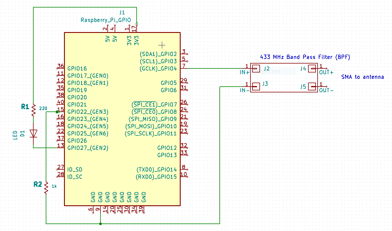
Here is the schematic:
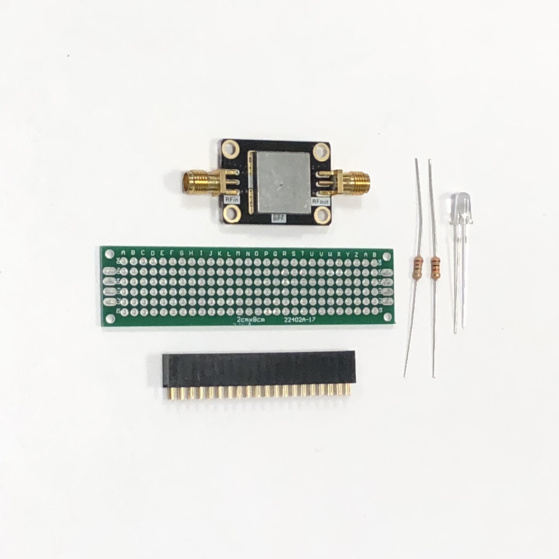
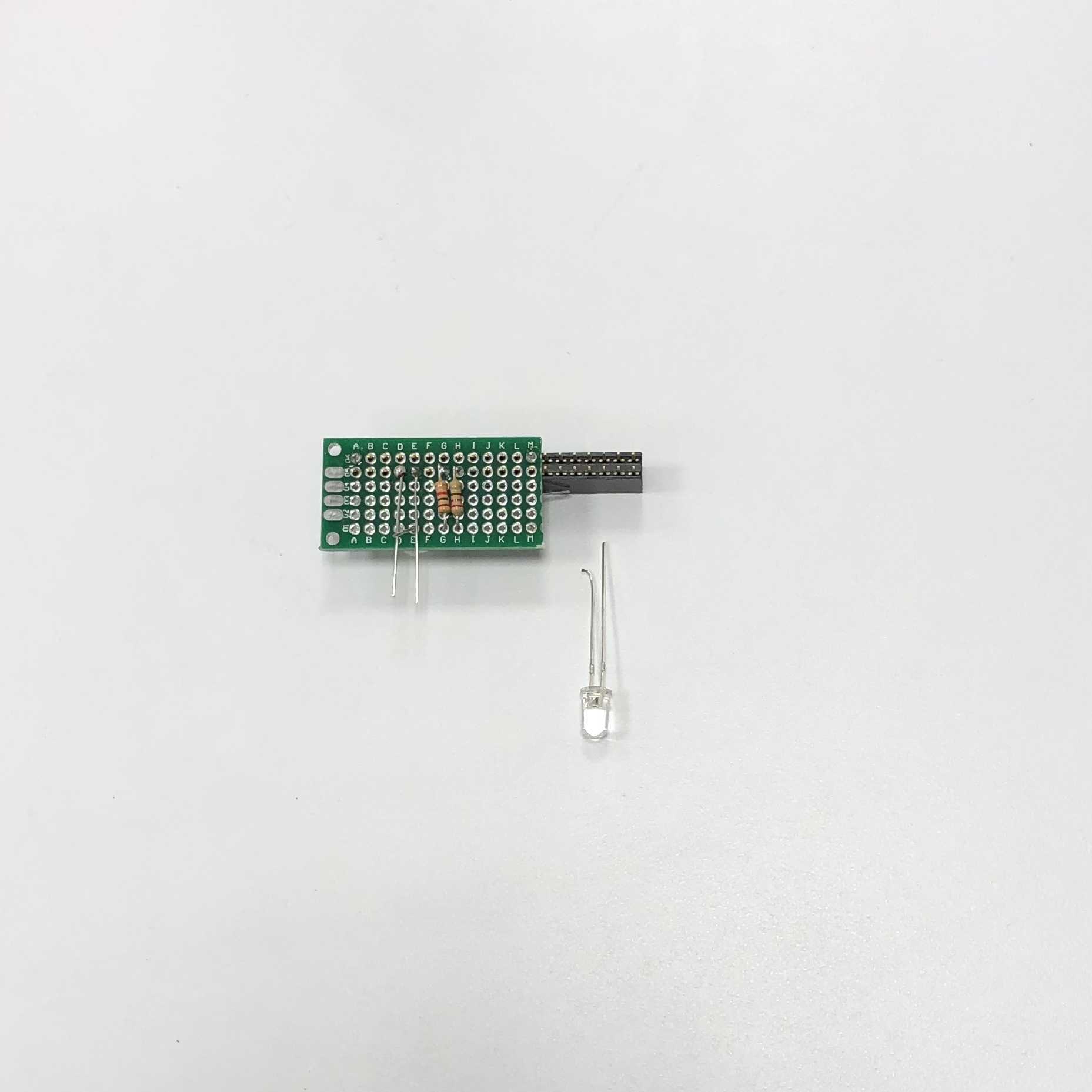
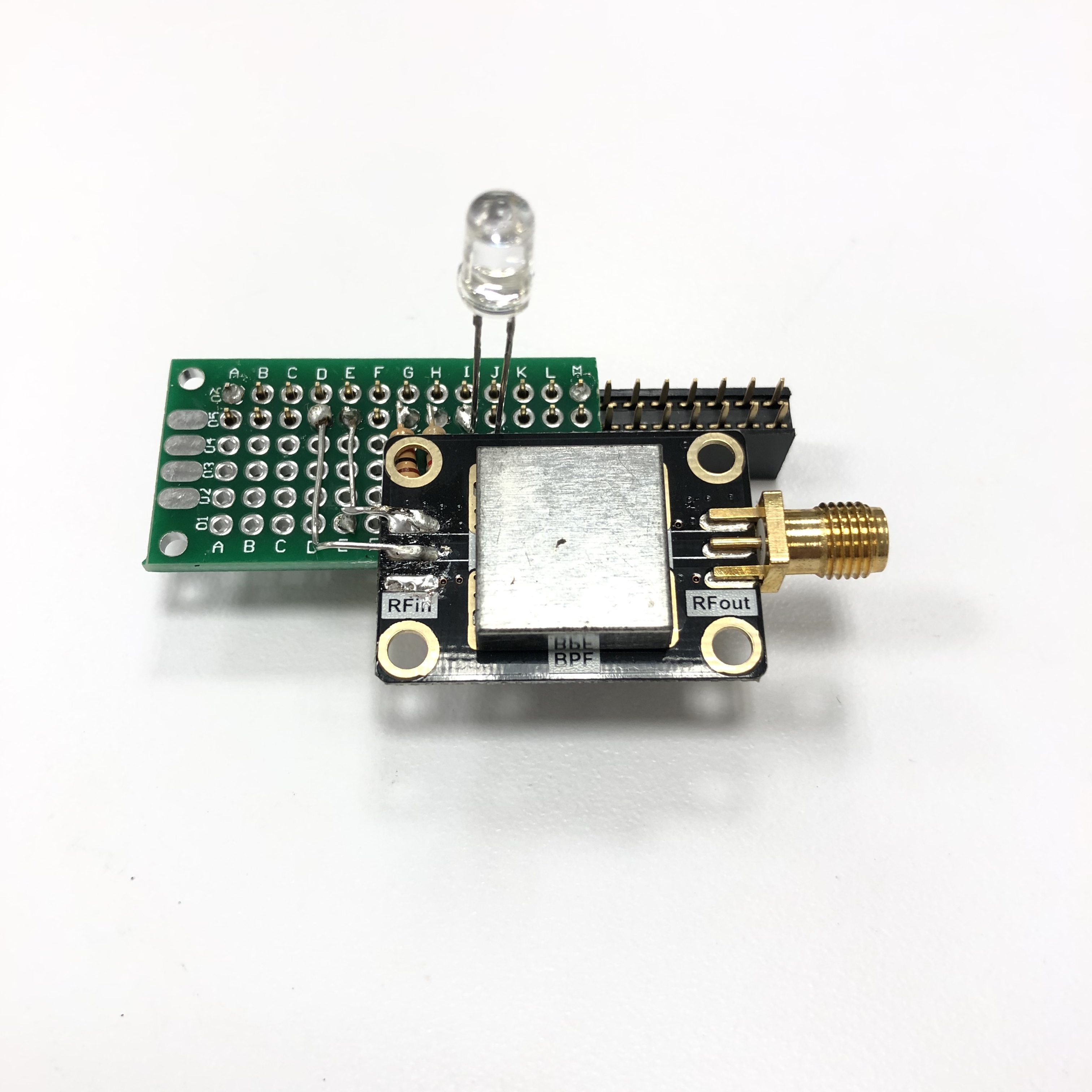
These parts are shown here:
Steps:
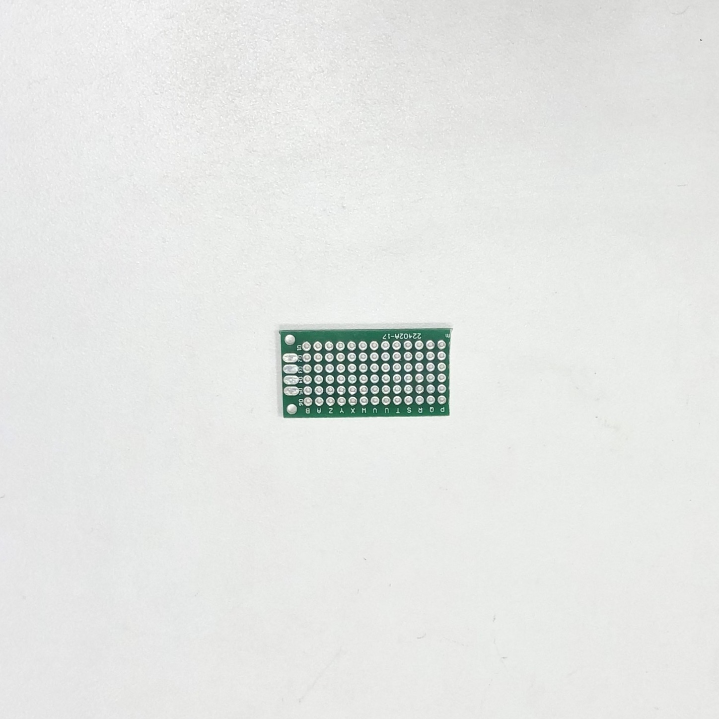
- Cut 2cm x 8cm protoboard in half using hacksaw (cut at row "O")
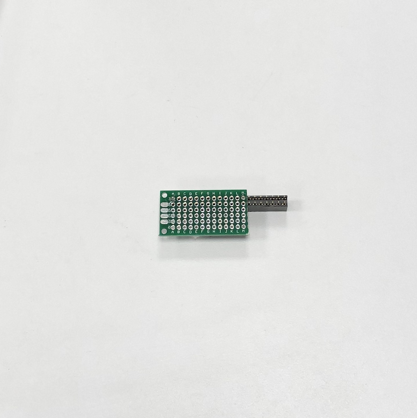
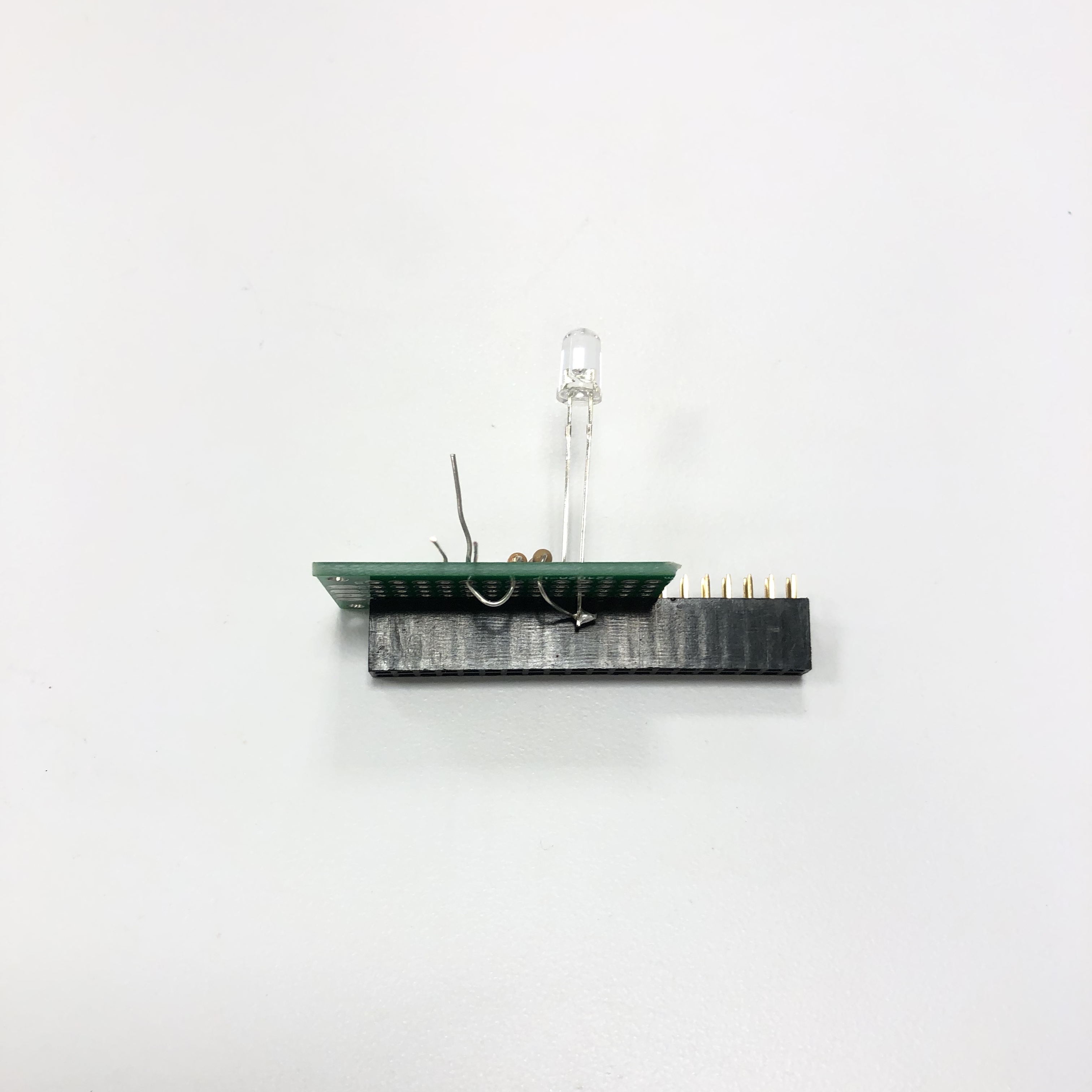
- Insert 2x20 header into board, columns A-M, rows 5-6. Solder a few pins at the end to hold in place.
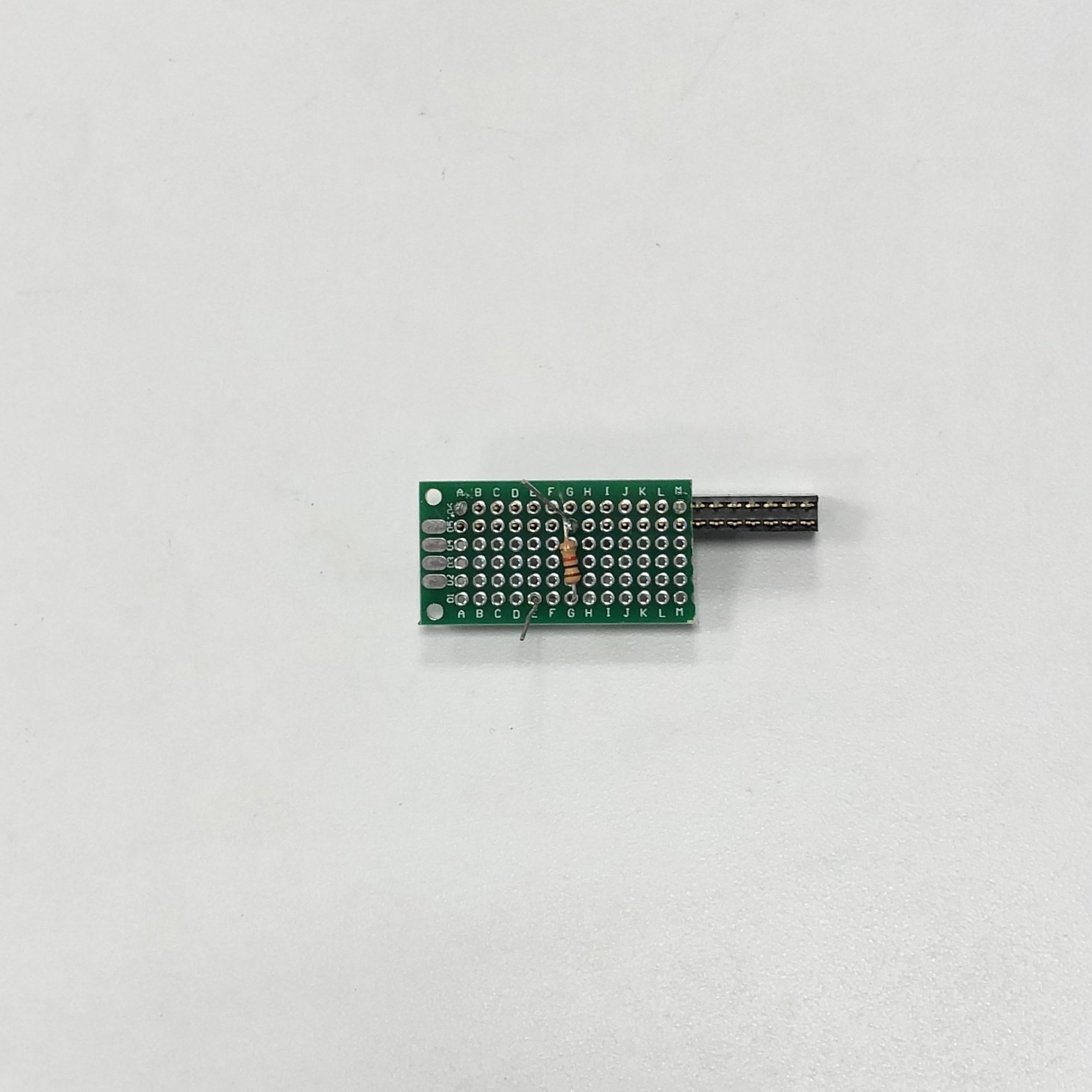
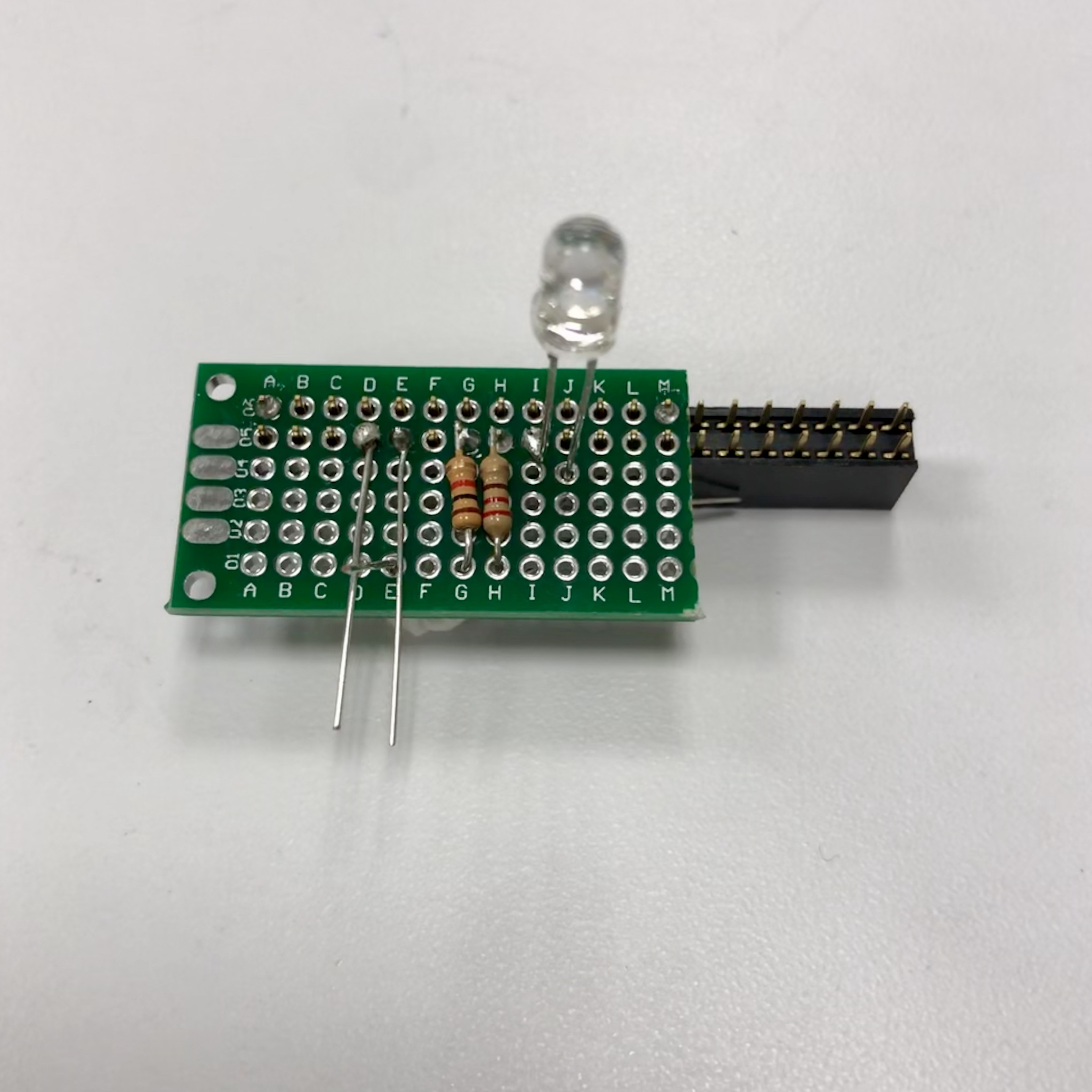
- Insert 1k Ohm resistor into G-1 and bend over so other lead touches the header pin at G-5. Solder onto header pin at G-5. Cut off excess and save for later.
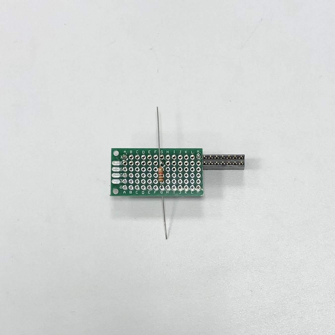
- On underside, insert end of 1k through E-1.
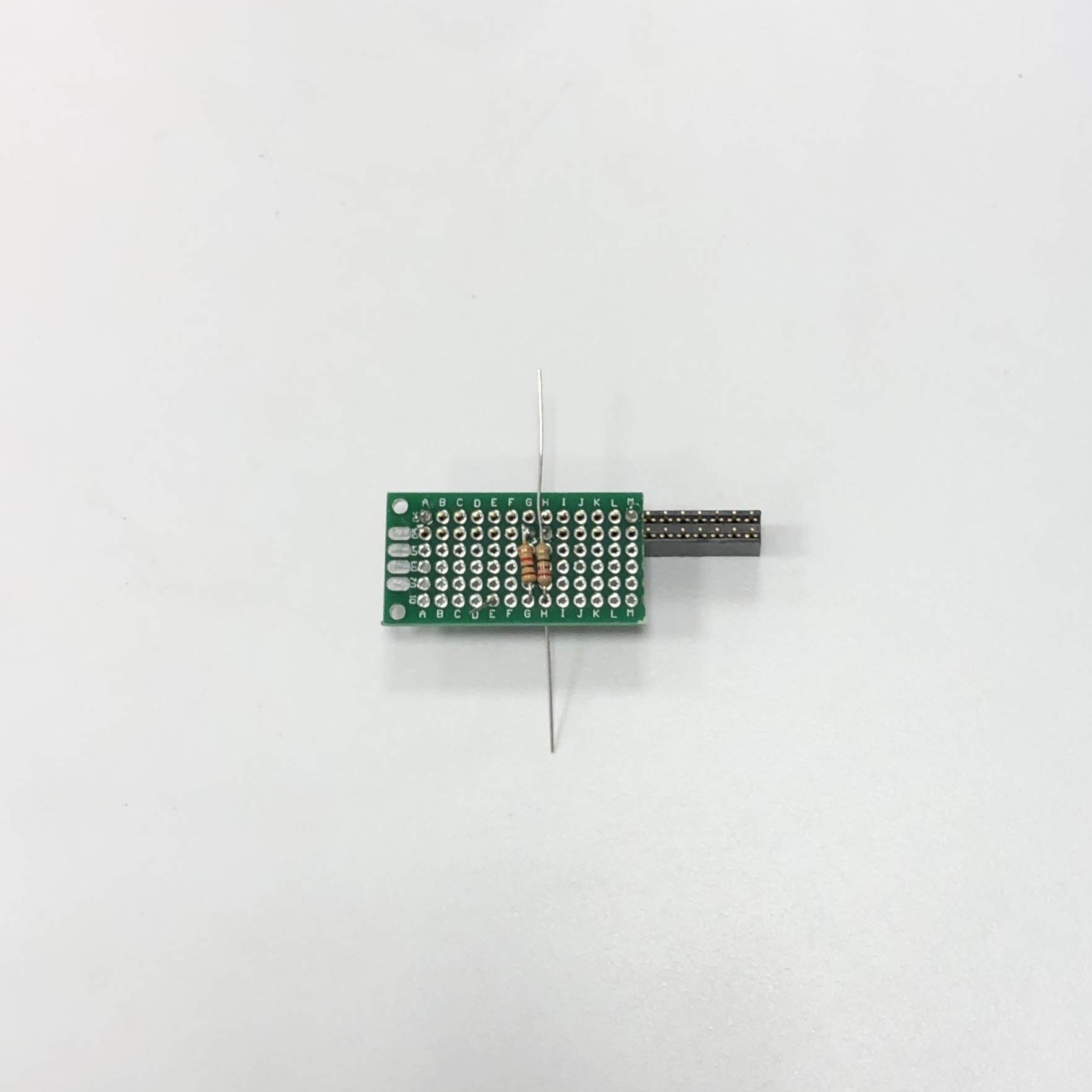
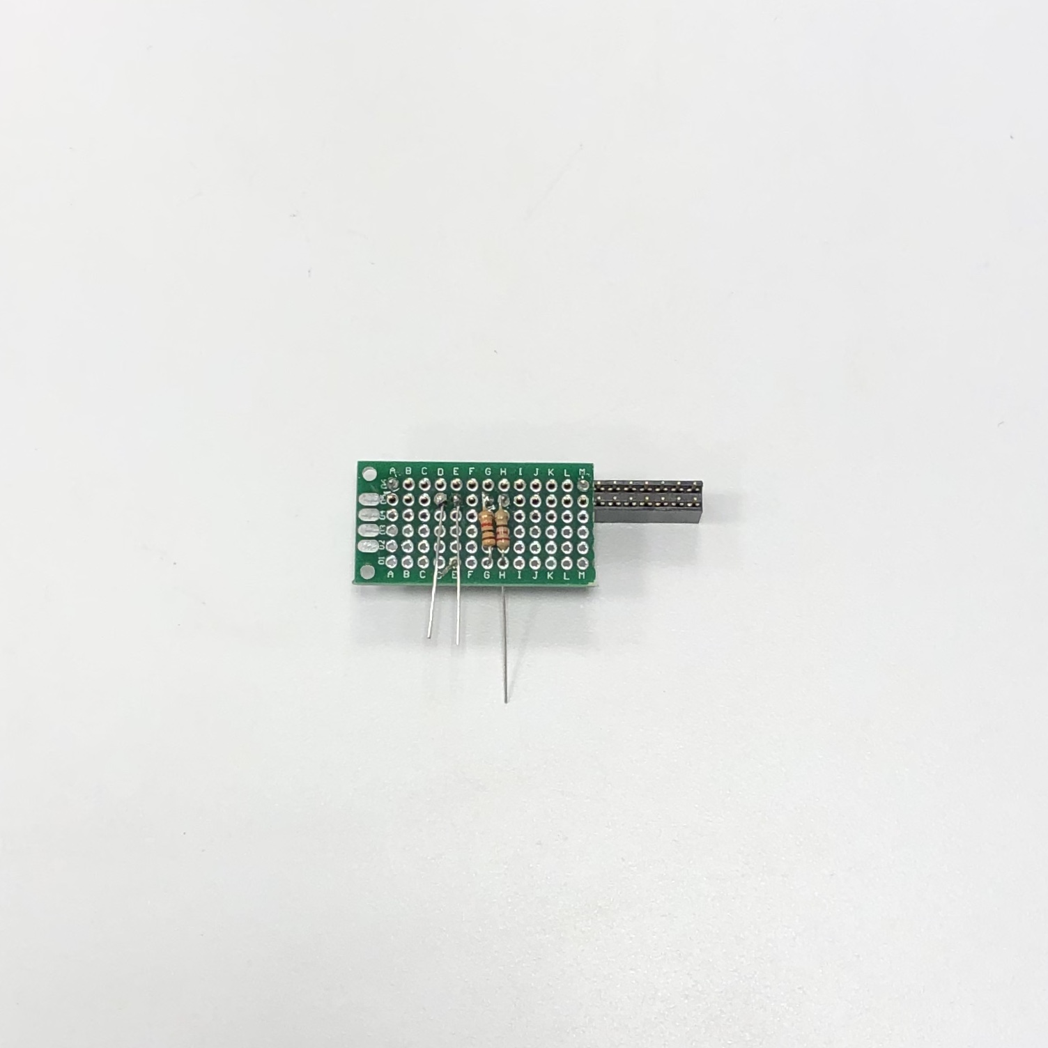
- Insert 220 Ohm resistor into H-1 and bend over so other lead touches the header pin at H-5. Solder onto header pin at H-5. Cut off excess and save for later.
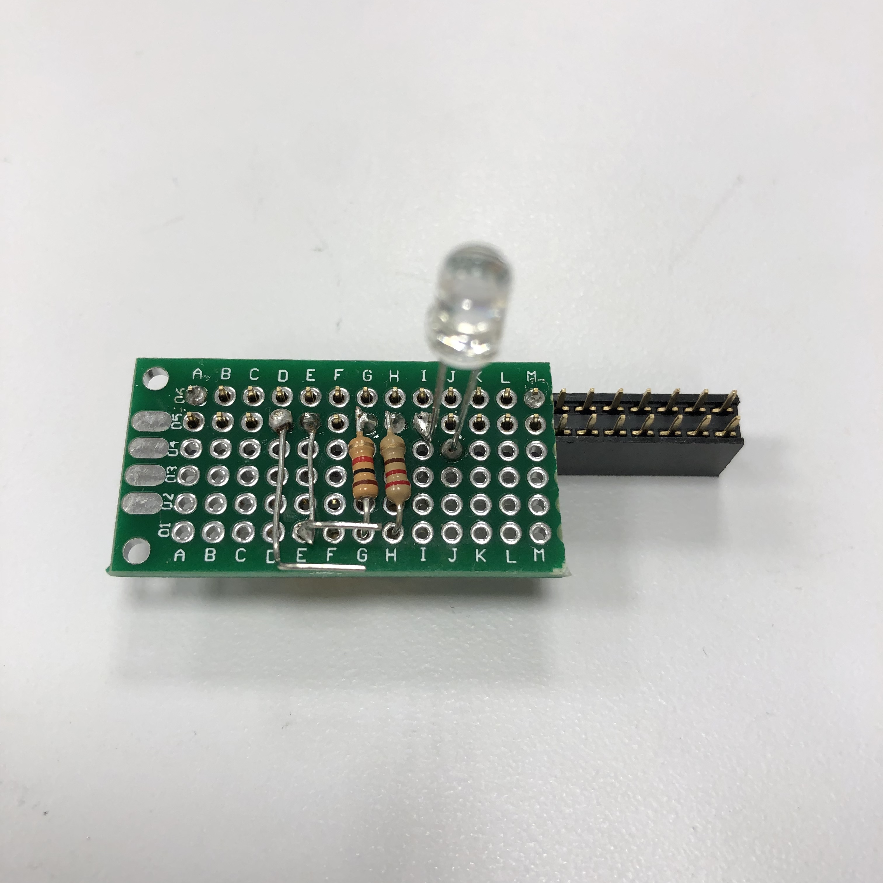
- Solder off-cuts from 220 Ohm and 1k Ohm resistors to the header pins at D-5 and D-6 so they lay flat across the protoboard
- Bend longer lead (anode) of LED at a right angle and cut off excess.
Insert other lead into J-4 so that the bent lead touches the header pin at I-5. Solder header pin at I-5 to LED lead.
- On the underside of the board, bend the 220 Ohm lead so that it touches the LED lead, solder together, and trim excess.
- Solder the lead from the 1k resistor to the wire at E-1.
- Unsolder the SMA connector in the BPF input. Do this by laying your soldering iron horizontally so it is touching all three solder joints, apply pressure outward when the solder is molten, and the connector should slide off. You may need to apply a small amount of solder to your iron so it heats up all three leads at the same time.
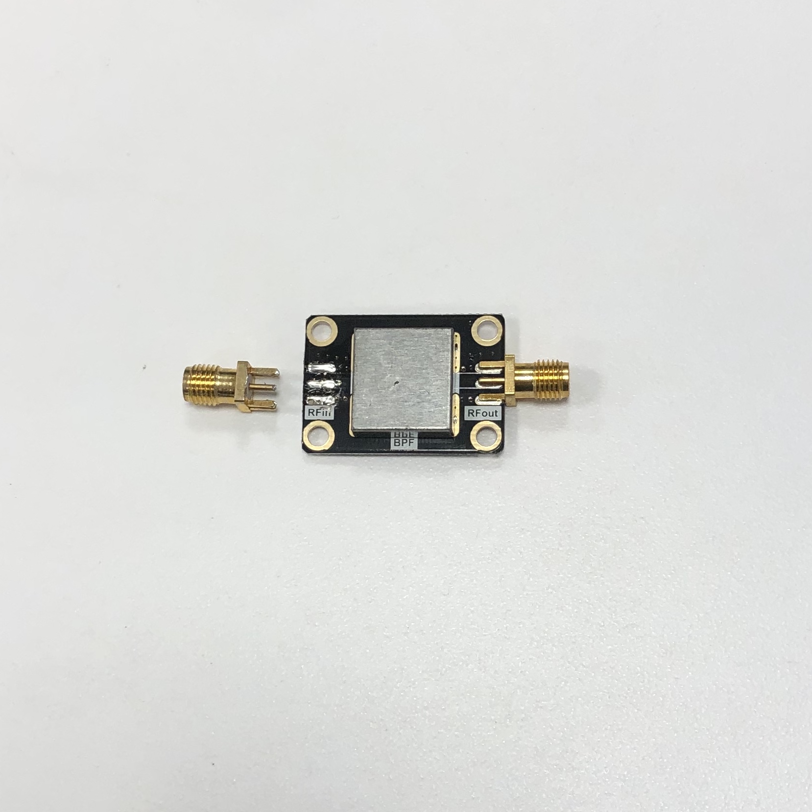
- Bend the two leads and trim so they line up with the center and outer connectors.
- Solder BPF
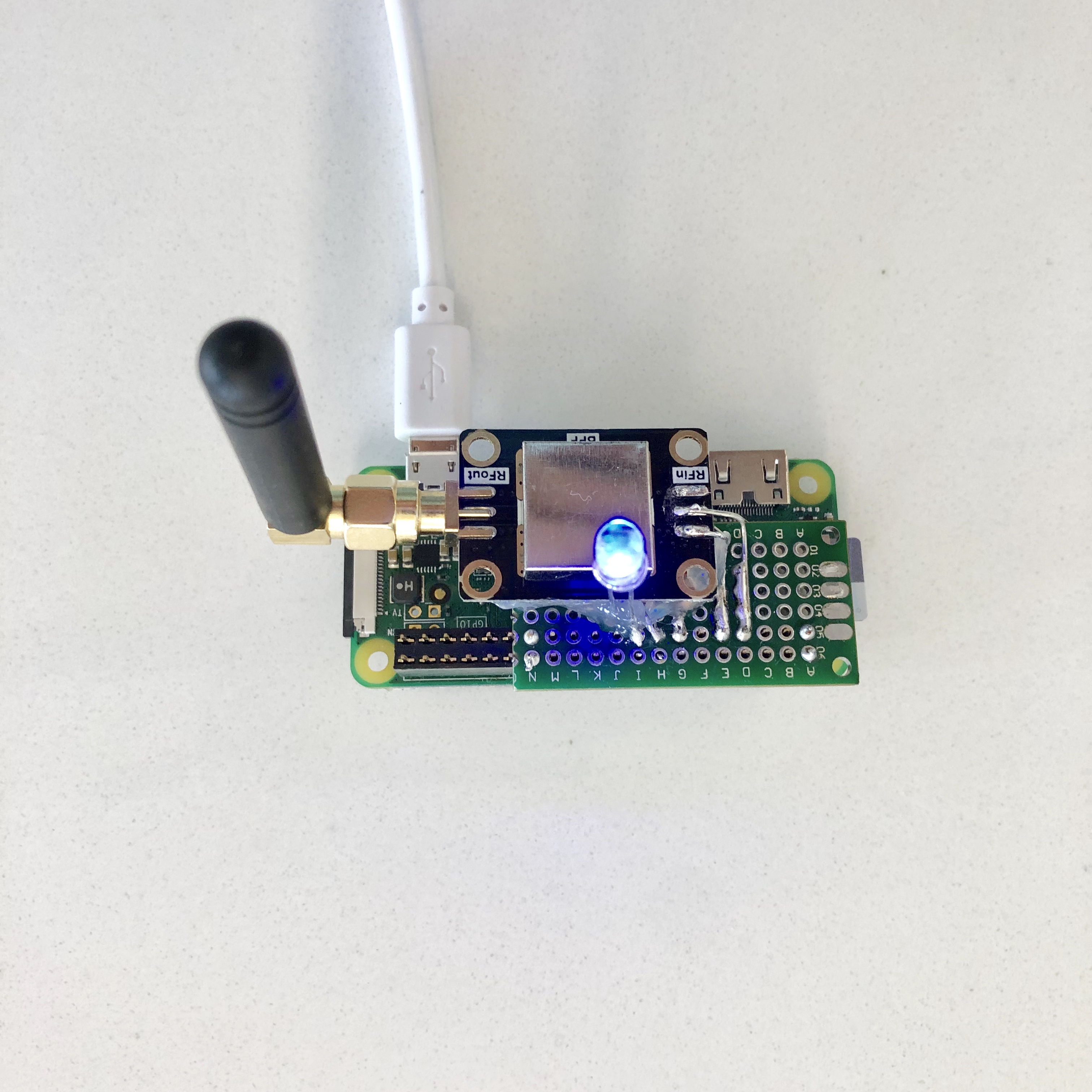
- Test board (install software as described below) The blue LED should blink 4 times when the code starts
- Hot glue the BPF to the board.
Installing the Software
These steps assume that you have configured Raspbian and installed the MoPower UPS V2 software.
When logged into the Pi type:
cd
git clone http://github.com/alanbjohnston/CubeSatSim.git
cd CubeSatSim
git checkout aprs-rpitx
Edit the file afsk/main.c to include your ham radio callsign. For example, using the nano editor, type:
nano afsk/main.c
Then use the down arrow to find the line #define CALLSIGN "" // Put your callsign here! position the cursor inside the double quotes "" and enter your callsign as a string. Press Ctrl-X then type y then hit Enter to save the file and exit the editor.
Compile the code by typing
make rebuild
Follow these steps to install DireWolf.
sudo apt-get install libasound2-dev
cd ~/CubeSatSim
git clone https://www.github.com/wb2osz/direwolf
cd direwolf
make -j
(takes a while)
sudo make install
make install-rpi
Install rpitx by typing
cd ~/CubeSatSim
git clone https://github.com/F5OEO/rpitx.git
cd rpitx
./install.sh
(Takes a while). It will prompt you if you want to modify /boot/config.txt file. Type a y and the script will complete.
sudo reboot now
After rebooting, type:
cd CubeSatSim
./radioafsk