Assembly instructions - The-Hybrid-Atelier/RheoBoard GitHub Wiki
This page mounts the parts, connects the electronics and the tubing, and checks the RheoBoardOTS - DIY panel. It ends when the hardware is assembled, the firmware has started, and USB Serial Monitor shows a first pressure reading.
Two air pumps and one valve run a REP (What is REP?). An ESP32 drives them, and a Qwiic MicroPressure sensor reads the pressure. Solder only when a board has no headers, or an actuator lead is not fitted.
- Mount the components
- Connect electronics and check wiring
- Connect tubing
- Install firmware
- Check power and idle behavior
- Read pressure
- Purchased parts are on Parts to buy. Printed parts are on Parts to 3D print.
- Wiring files:
electronic-wiringandtube-wiring. - Tools are on Assembly tools.
- Read Safety before you connect the adapter or USB.
USB powers the ESP32. The 12 V adapter does not power the ESP32. These steps leave the battery disconnected.
Leave the adapter unplugged from the wall until Step 05. After the pressure reading in Step 06, unplug it from the wall, then disconnect USB.
Use two copies of pump_holder.STEP.
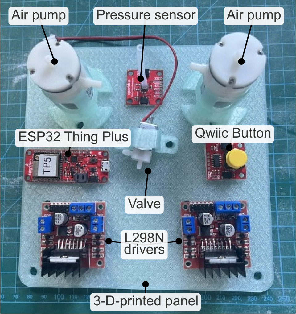
Component layout overview. The seesaw board is not shown.
Actions:
- Use one pump as PUMP1, the vacuum pump, and the other pump as PUMP2, the pressure pump. L298N #1 drives both pumps. L298N #2 drives the valve.
- Put PUMP1 in one printed pump holder and PUMP2 in the other. Put the valve on the valve bracket.
- Join the two pump holders and the valve bracket to the base panel with zip ties.
- Fasten the seesaw, L298N #1, L298N #2, the ESP32 Thing Plus, the Qwiic MicroPressure sensor, and the Qwiic Button to the base panel with zip ties.
- Leave a clear path for the cables and the tubing.
Check before continuing:
- All listed components are secured
- Cable and tube paths are clear
Keep USB disconnected, the battery disconnected, and the adapter unplugged from the wall while you wire and while you check continuity.

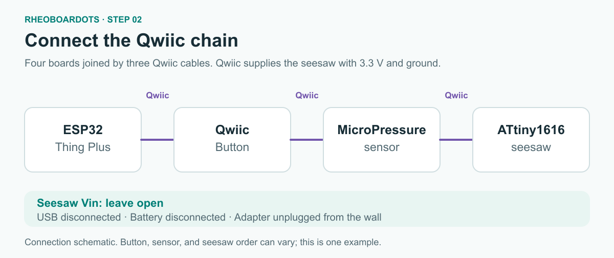
Qwiic chain.
Qwiic supplies 3.3 V and ground to the seesaw. Addresses are on Firmware.
- Connect the ESP32 Thing Plus, the Qwiic Button, the MicroPressure sensor, and the ATtiny1616 seesaw with three Qwiic cables. The order of the button, the sensor, and the seesaw does not matter.
- Leave the seesaw
Vinpin open.
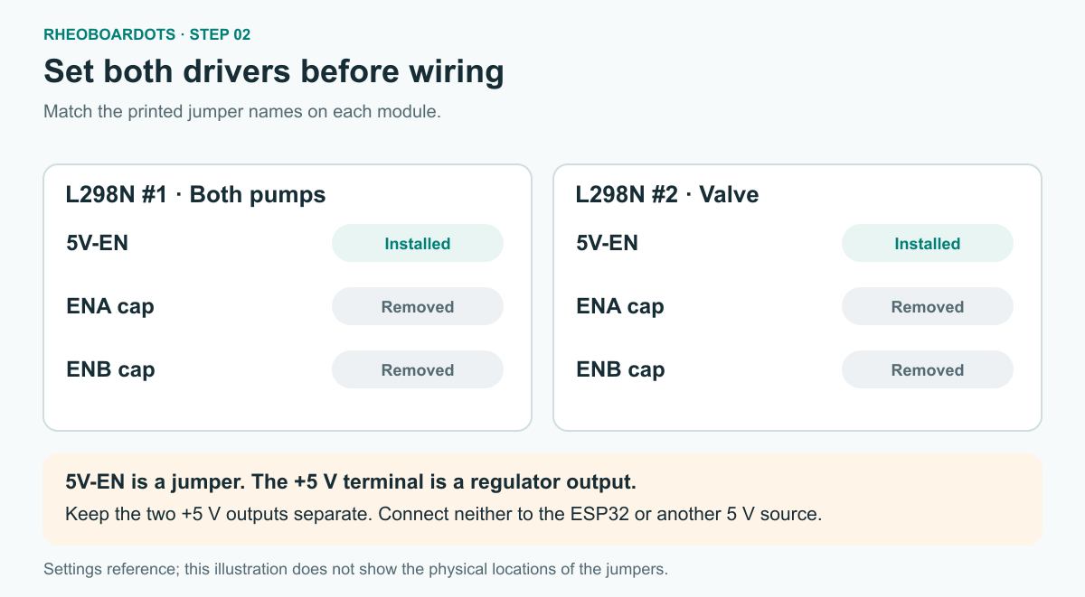
This illustration does not show where the jumpers sit on the board.
Set the jumper caps before you connect the signal wires.
- Set the caps to this table.
| Jumper | L298N #1 | L298N #2 |
|---|---|---|
5V-EN |
Installed | Installed |
| ENA jumper cap | Removed | Removed |
| ENB jumper cap | Removed | Removed |
The installed 5V-EN cap is the jumper. The +5 V terminal is that module's regulator output.
- Connect each row. Leave seesaw pin 4 open.
| From | To | Controls |
|---|---|---|
| Seesaw pin 0 | L298N #1 ENA | PUMP1 vacuum |
| Seesaw pin 1 | L298N #1 ENB | PUMP2 pressure |
| Seesaw pin 5 | L298N #2 ENB | Valve |
- Connect each row. Do not connect the two modules'
+5 Voutputs together. Do not connect either+5 Vterminal to the ESP32 or to any other 5 V source.
| From | To |
|---|---|
| L298N #1 IN1 | This module's +5 V terminal |
| L298N #1 IN2 | This module's GND |
| L298N #1 OUT1 and OUT2 | PUMP1 leads |
| L298N #1 IN3 | This module's +5 V terminal |
| L298N #1 IN4 | This module's GND |
| L298N #1 OUT3 and OUT4 | PUMP2 leads |
| L298N #2 ENA, IN1, IN2, OUT1, and OUT2 | Open |
| L298N #2 IN3 | This module's +5 V terminal |
| L298N #2 IN4 | This module's GND |
| L298N #2 OUT3 and OUT4 | Valve leads |
The adapter plug is center-positive. The center contact is positive. The outer sleeve is negative.
The wall-adapter barrel plug goes into the female jack on the SparkFun DC Barrel Jack Adapter - Female (PRT-10288). The PRT-10288 screw terminals connect to a breadboard. The breadboard connects to the L298N motor-power and GND screws. The ALT-1202 plug is documented as 5.5 mm outside and 2.5 mm inside. The PRT-10288 jack is 5.5×2.1 mm. Whether that plug fits that jack is unconfirmed. Confirm this plug-to-jack fit before proceeding to power-on in Step 05.
- Connect each row. The center contact is positive and goes to both L298N motor-power inputs. The outer sleeve is negative and goes into the common ground: both L298N GND screws and the ESP32 GND pin.
| From | To |
|---|---|
| PRT-10288 positive screw terminal, via a breadboard | L298N #1 motor-power screw and L298N #2 motor-power screw |
| PRT-10288 negative screw terminal, via a breadboard | L298N #1 GND, L298N #2 GND, and the ESP32 GND pin |
The outer-sleeve connection is the common ground.
With the adapter unplugged from the wall, USB disconnected, and the battery disconnected, set the meter to continuity. Leave the power wiring connected. One probe can touch a PRT-10288 screw terminal. The other probe touches an L298N screw, or the ESP32 GND pin when the pair lists that pin. Remove power before this measurement.
Expect continuity for every listed pair. This checks only those connections, not the whole circuit. Do not probe from the PRT-10288 positive screw terminal to a GND screw or to the ESP32 GND pin.
- For each row, touch one probe to each point.
| One probe | Other probe |
|---|---|
| PRT-10288 positive screw terminal | L298N #1 motor-power screw |
| PRT-10288 positive screw terminal | L298N #2 motor-power screw |
| PRT-10288 negative screw terminal | L298N #1 GND screw |
| PRT-10288 negative screw terminal | L298N #2 GND screw |
| PRT-10288 negative screw terminal | ESP32 GND pin |
Check before continuing:
- Three Qwiic cables join the four boards, and seesaw
Vinis open - Both
5V-ENjumpers are installed, and the ENA and ENB caps are removed on both modules - Seesaw pin 4 is open, and L298N #2 ENA, IN1, IN2, OUT1, and OUT2 are open
- The two modules'
+5 Vterminals are not connected to each other - USB is disconnected, the battery is disconnected, and the adapter is unplugged from the wall
- The meter showed continuity on each listed pair
Leave USB disconnected, the battery disconnected, and the adapter unplugged from the wall.
Port names are in Tube ports. The ZR370-02PM draws air in the side port and pushes it out the tubing port. Reversing the motor wires does not flip that airflow.
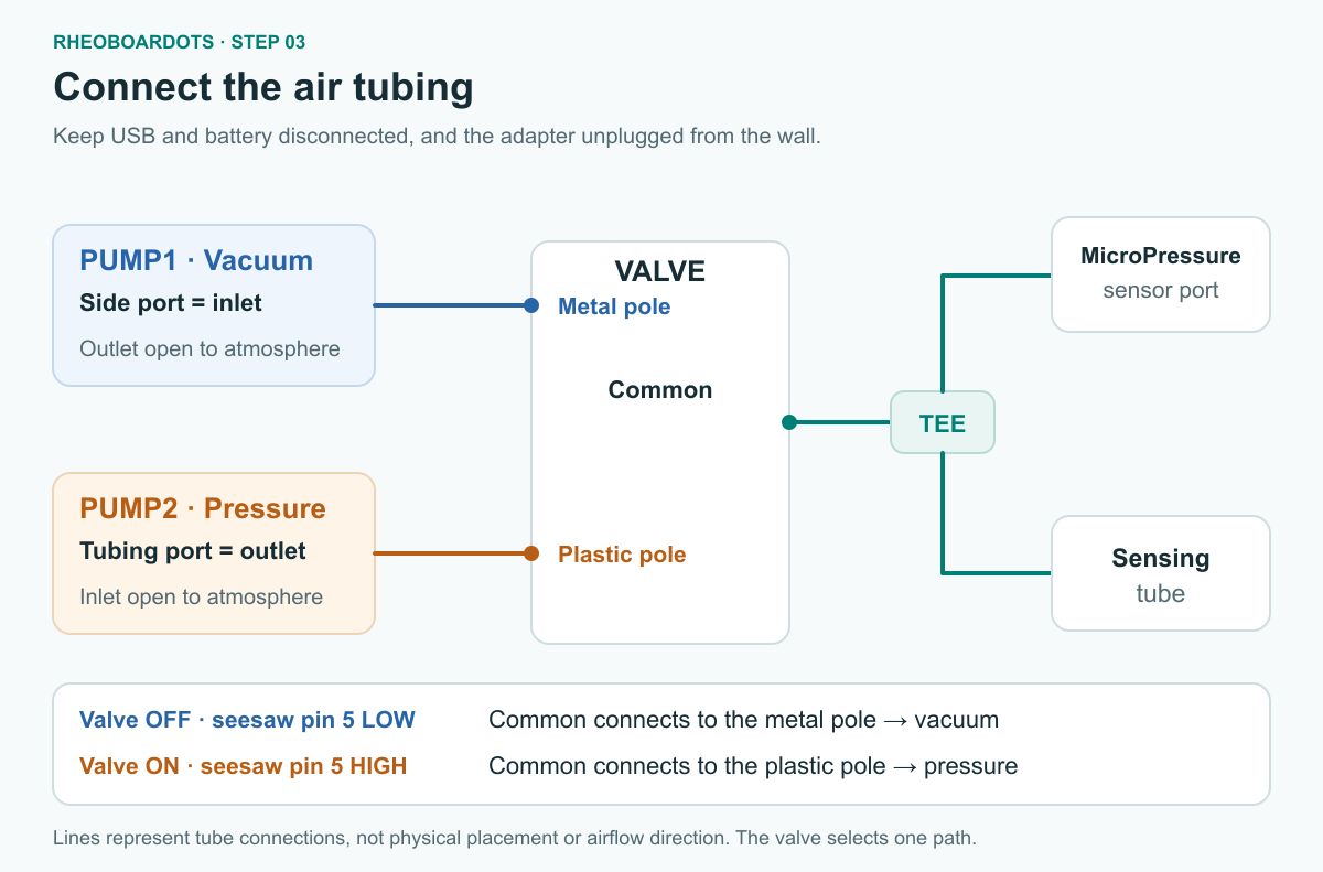
Lines show which ports join, not where the parts sit.
| Valve | Seesaw pin 5 | Common connects to |
|---|---|---|
| Off | Low | Metal pole (PUMP1, vacuum) |
| On | High | Plastic pole (PUMP2, pressure) |
- Connect each row.
| From | To |
|---|---|
| PUMP1 side port (inlet) | Valve metal pole |
| PUMP1 tubing port (outlet) | Open to atmosphere |
| PUMP2 tubing port (outlet) | Valve plastic pole |
| PUMP2 side port (inlet) | Open to atmosphere |
| Valve common | Tee |
| One tee branch | MicroPressure sensor port |
| Other tee branch | Sensing tube |
Check before continuing:
- USB is disconnected, the battery is disconnected, and the adapter is unplugged from the wall
- PUMP1's side port goes to the valve metal pole, and its tubing port is open
- PUMP2's tubing port goes to the valve plastic pole, and its side port is open
- Valve common goes to the tee, one branch goes to the MicroPressure sensor, and the other branch goes to the sensing tube
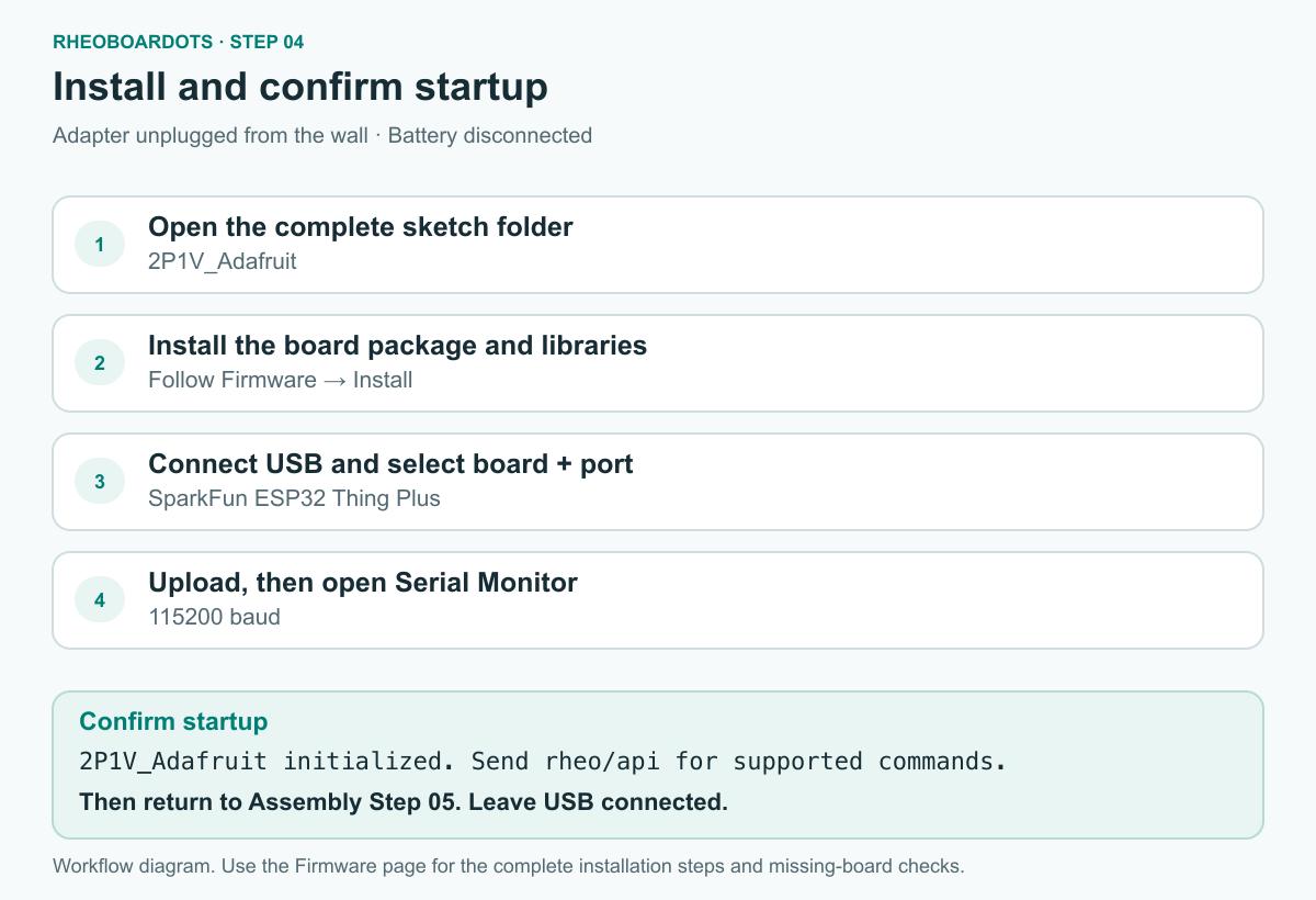
Install and startup workflow.
Install the sketch under Install on the Firmware page. Leave the battery disconnected. Leave the 12 V adapter unplugged from the wall.
When the RheoBoardOTS - DIY startup check passes, return to Step 05: Check power and idle behavior. Leave USB connected. Leave the adapter unplugged from the wall.
Check before continuing:
- The RheoBoardOTS - DIY startup check passed
- USB is connected
- The battery is disconnected
- The adapter is unplugged from the wall
Start here after the Firmware startup check has passed. USB is connected. The battery stays disconnected. The adapter is unplugged from the wall.
The 12 V adapter feeds both L298N motor inputs directly, with no extra converters. The pumps are rated about 4.5 V and the valve about 6 V. This direct drive has been operated, including short REPs and continuous pumping. Whether that stays inside those ratings is still an open engineering question.
Keep the adapter unplugged until the plug-to-jack compatibility described in Step 02 has been confirmed.
Actions:
- Set the panel on a stable surface. Leave slack in the tubing, the USB cable, and the adapter cable.
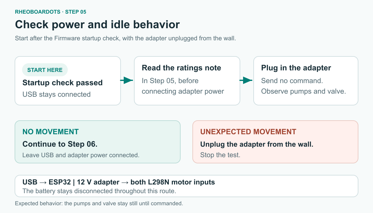
Idle check with no command sent.
- Plug the adapter into the wall. Its DC wiring stays on both L298N motor-power inputs. Leave USB connected. Leave the battery disconnected.
- Watch the pumps and the valve with no command sent. They should stay still. If a pump or the valve moves, unplug the adapter from the wall and stop.
Check before continuing:
- The ALT-1202 plug fit in the PRT-10288 jack was confirmed before the adapter was plugged into the wall
- The adapter is plugged into the wall, and its output feeds both L298N motor inputs
- USB is connected and the battery is disconnected
- With no command sent, the pumps and the valve stayed still
This test uses the sketch defaults on Firmware. The sensing tube has no required condition for this first reading.
You need:
- USB connected, from Step 05
- The 12 V adapter plugged into the wall, from the powered check
- The battery disconnected
- Serial Monitor at 115200 baud
Actions:
- In Serial Monitor, set the baud rate to 115200. Set the line ending to Newline, Carriage return, or Both NL & CR. The sketch treats a newline or a carriage return as the end of a command.
- Send this command. Sending
REPoperates the pumps.
REP
- Read the monitor while the REP runs.
| Output | Meaning |
|---|---|
#REP_START |
The REP has started. The line continues with a pressure reading in pascals. |
#S,<ms>,<Pa> |
A pressure sample during the REP. <ms> is milliseconds since the REP started. <Pa> is pressure in pascals. That field must be a number. It is invalid when it is not numeric, nan, or empty. |
#PH,<ms>,<phase> |
The phase changed. <ms> is milliseconds since the REP started. <phase> is the phase name. |
#REP_END |
The REP has ended. |
The sketch does not print #S lines while it is idle.
- After
#REP_END, unplug the adapter from the wall, then disconnect USB.
Treat this as a first pressure reading. It is not a calibration, and it is not a validated material measurement.
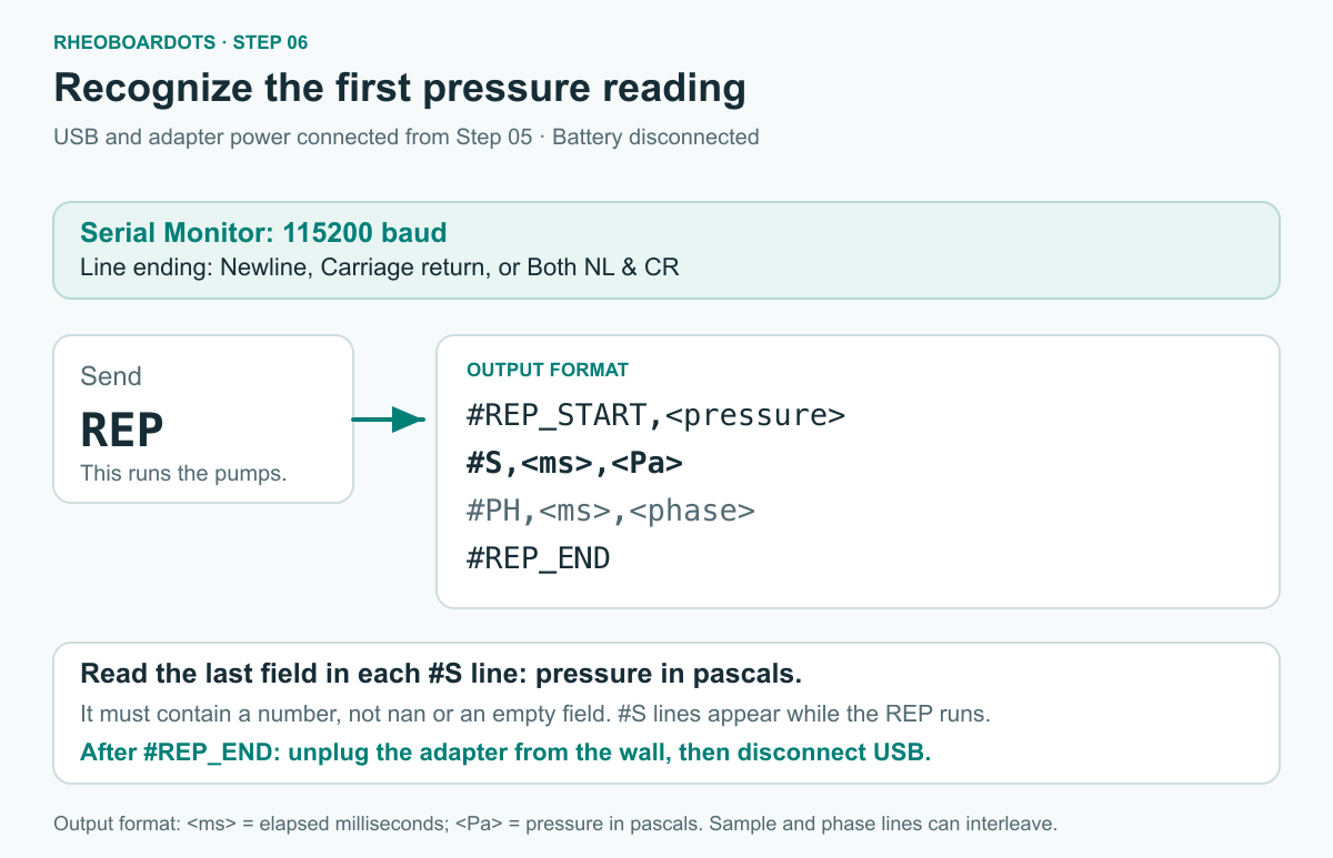
Format guide. The fields are symbolic. This is not a Serial Monitor capture and not a measurement result.
If #REP_START is missing, no #S sample lines appear, an #S pressure field is not numeric, nan, or empty, or #REP_END does not appear, unplug the adapter from the wall, then disconnect USB, before any physical check. Then use the RheoBoardOTS - DIY startup check.
Check:
- The monitor showed
#REP_START,#S,<ms>,<Pa>lines during the REP,#PH,<ms>,<phase>as the phase changed, and#REP_END - The last field of each
#Sline was numeric, and was notnanor empty - After the reading, the adapter is unplugged from the wall and USB is disconnected
- The battery is disconnected
Next: Maintenance.