MAS FASA Retro Seat 1 - MOARdV/MOARdVPlus GitHub Wiki
IVA description for the Retro Apollo Command Pod.
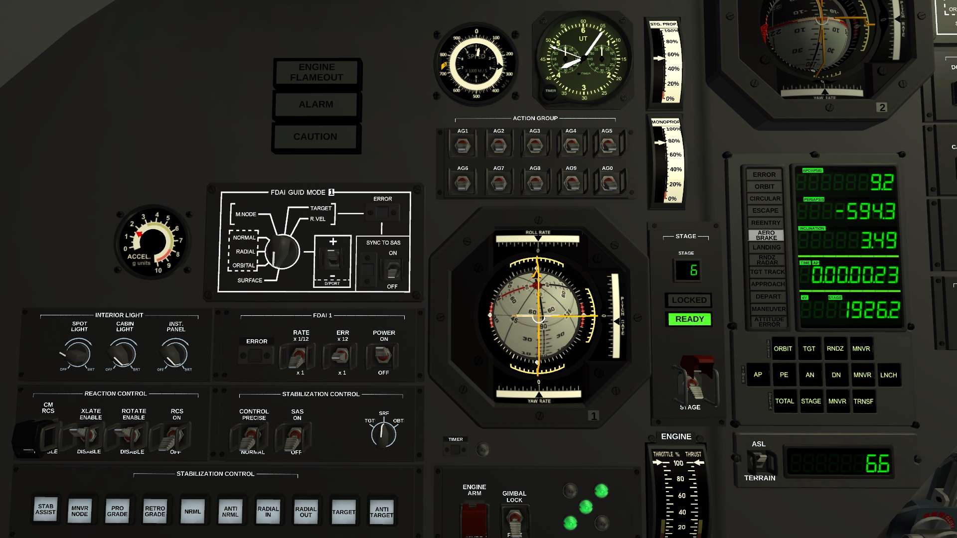
Seat 1 is focused on normal flight operations and overall vessel control. This crew station is focused on the first of two Flight Director / Attitude Indicator instruments (FDAI #1).
MAS FASA Retro Seat 2 and MAS FASA Retro Seat 3 have separate pages.
This guide will start on the left side of the workstation and proceed to the right side, going from top to bottom on each column.
(or see here)
First Column
ACCEL Gauge
This gauge reports the acceleration the command pod is currently experiencing.
INTERIOR LIGHT Panel
The Interior Light panel provides rheostat control over the instrumentation backlight (INST. PANEL) and two interior lights (SPOT LIGHT and CABIN LIGHT). Press and hold on the left or right side of the knobs to adjust these settings.
REACTION CONTROL Panel
The Reaction Control panel provides controls to enable the RCS system (RCS switch), as well as indicate whether the RCS should provide thrust for rotation (ROTATE) and translation (XLATE). In addition, the Command Module RCS system can be enabled (CM RCS). The CM RCS is normally disabled until reentry.
Second Column
ALARM Lamps
The engine flameout, master alarm, and master caution warning lights are on the top of the second column.
FDAI 1 GUID MODE Panel
The control panel for FDAI 1 is located below the alarm lamps. This panel includes a dial to select which mode the FDAI error needles are in (surface prograde/retrograde, orbital prograde/retrograde, etc). In addition, it includes a +/- toggle switch to select between the two available modes (eg, SURFACE and + indicates surface-relative prograde, while SURFACE and - indicates surface-relative retrograde). The panel also includes a SYNC TO SAS switch that will track the current SAS setting, when SAS is not set to Stability Assist.
If the ERROR flag indicator activates, it indicates that the current combination of modes is invalid, such as using Sync to SAS when SAS is set to Stability Assist, or TARGET + when there is no target.
FDAI 1 Panel
This control panel for FDAI 1 is used to activate the instrument (POWER switch), and to adjust the scale for the error needles (ERR switch) and rate arrows (RATE switch). It also includes an ERROR flag indicator.
STABILIZATION CONTROL Panel
There are two panels for SAS.
The smaller one, below FDAI 1, has the SAS enable switch (SAS switch), the switch to control precise control mode (CONTROL switch), and a three-position switch to control speed mode: SRF for surface-relative mode, OBT for orbital mode, and TGT for target mode. The switch will not allow you to select invalid modes.
The larger panel selects the SAS mode. When SAS is active, the current mode is illuminated in amber.
Third Column
Speed Gauge
The speed gauge at the top of the 3rd column displays speed, in m/s, for the speed mode selected on the rotary switch on the Stabilization Control panel. The outer ring displays speeds in m/s, while the inner ring displays speeds in km/s. The gauge goes out of range at 9000 m/s. When in surface-relative mode, a yellow flag with an 'S' is visible on the left side of the gauge. When in target-relative mode, a red flag with a 'T' is visible.
Clock / Timer
The clock / timer reports UT on the primary face (compatible with standard 6 hour Kerbal days, or with 24 hour Earth days). It also contains a timer activated by pressing the TIMER button in the lower-left corner. While active (red TIMER flag visible in the lower-center of the clock face), the seconds and minutes hands on the two small timer dials will increase. The timer may be stopped by pressing the TIMER button again. The timer dials will display the time when it was stopped. Pressing TIMER a third time will reset the timer to 0.
ACTION GROUP Panel
The Action Group panel allows switch of all ten standard action groups.
FDAI 1
FDAI #1 is the center of this panel. When active, the current attitude is displayed on the navball.
The orange needles display the difference between the vessel's current orientation and the mode selected on FDAI GUID #1. The bottom needle displays the yaw error, the right needle displays the pitch error, and the top needle displays the roll error (valid only in docking port alignment mode). The range of the error needles is controlled using the ERR switch on the FDAI panel. At maximum precision, each tick on the error gauge represents 1 degree of error (with a maximum error displayed of 6 degrees). At the middle precision, each tick represents 6 degrees of error (36 degrees maximum error), while the minimum precision mode displays 12 degrees per tick (72 degrees maximum).
An black chevron with orange edges rotates around the navball to display the vessel's current surface-relative roll.
Black arrows at the bottom, right, and top portray the current yaw, pitch, and roll rate, respectively, in degrees per second. The precision of these rate arrows can be adjusted using the RATE switch on the FDAI 1 panel.
See also How to FDAI.
TIMER Repeater
When a timer is active, the TIMER flag indicator will display green. When there is less than a minute before the timer expires, the adjacent green lamp illuminates. At T-15 seconds, the lamp will begin blinking.
ENGINE Panel
The Engine panel allows some control over the engines currently active on the vessel. The ENGINE ARM switch allows the currently-staged engines to be switched on or off. The GIMBAL switch allows the gimbals to be locked or unlocked. The five indicator lamps represent the current number of active engines (S1E configurations will show 3, one for the F-1 engine and two for the roll control engines).
Fourth Column
STG. PROP. and MONOPROP Gauges
The STG. PROP. gauge reports the remaining propellant for the current stage as a percentage of maximum capacity. The MONOPROP gauge reports the availability of monopropellant for RCS thrusters.
STAGE Panel
The Stage panel shows the current active stage on the vessel, along with indicator tableaux reporting when staging is available (READY) or locked (LOCKED). Below these tableaux is the stage switch. When the red cover is closed, staging is locked.
ENGINE Gauge
The Engine gauge shows the current commanded throttle position, as well as the amount of thrust currently being delivered by the active engines.
Fifth Column
FDAI 2
Partially visible in the picture, FDAI #2 is at the top of this column. Controls are located in seat 3's work area.
DSKY Panel
The DSKY panel is below FDAI #2. This instrument is described in more detail in How to DSKY.
As a very rough guideline, the top row of buttons (ORBIT, TGTn RNDZ, MNVR) select the data displayed on the top three rows of the instrument. The middle row of buttons (AP, PE, AN, DN, MNVR, and LNCH) control the timer displayed on the fourth row of the instrument. The bottom row of buttons (TOTAL, STAGE, MNVR, TRNSF) report either available delta-V (TOTAL and STAGE), the dV required for a maneuver (MNVR), or the dV required to initiate a Hohmann transfer (TRNSF).
ALTIMETER Display
A digital altimeter is below the DSKY. It can be switched between altitude above datum (ASL) or altitude above ground (TERRAIN). Values are in kilometers.