MAS FASA Retro Seat 3 - MOARdV/MOARdVPlus GitHub Wiki
IVA description for the Retro Apollo Command Pod.
Seat 3 controls multiple tasks.
MAS FASA Retro Seat 1 and MAS FASA Retro Seat 2 have separate pages.
This guide will start on the left side of the workstation and proceed to the right side, going from top to bottom on each column.
(or see here)
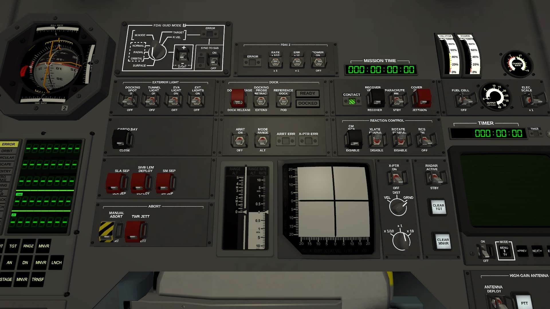
Left Column
FDAI 2 GUID MODE Panel
The control panel for FDAI 2 is located below the alarm lamps. This panel includes a dial to select which mode the FDAI error needles are in (surface prograde/retrograde, orbital prograde/retrograde, etc). In addition, it includes a +/- toggle switch to select between the two available modes (eg, SURFACE and + indicates surface-relative prograde, while SURFACE and - indicates surface-relative retrograde). The panel also includes a SYNC TO SAS switch that will track the current SAS setting, when SAS is not set to Stability Assist.
If the ERROR flag indicator activates, it indicates that the current combination of modes is invalid, such as using Sync to SAS when SAS is set to Stability Assist, or TARGET + when there is no target.
EXTERIOR LIGHT Panel
The Exterior Light panel is used to activate the docking spotlight (DOCKING SPOT switch), the LEM access tunnel light (TUNNEL LIGHT switch), the EVA light boom (EVA LIGHT switch), and the stock Lights action group (EXT. LIGHTS switch).
CARGO BAY Panel
The switch to open the SM cargo bay is on this panel. It includes a black cover to prevent accidental presses.
SLA/SM SEP Panel
The CSM can be decoupled from the S-IVB stage SLA by pressing the SLA SEP switch. The LEM or OM can be decoupled from the S-IVB by pressing the SIVB LEM DEPLOY switch. The CM can be separated from the SM (for reentry) by pressing the SM SEP switch.
All switches are protected by red covers to prevent accidental presses.
ABORT Panel
A manual abort may be initiated by pressing the MANUAL ABORT switch. The Boost Protective Cover and Launch Escape Tower may be jettisoned by using the TWR JETT switch. Both switches are covered to prevent accidental presses.
It is recommended that the ABORT cover be opened prior to launch, and closed once the BPC / LET have been jettisoned.
Middle Column
FDAI 2 Panel
This control panel for FDAI 2 is used to activate the instrument (POWER switch), and to adjust the scale for the error needles (ERR switch) and rate arrows (RATE switch). It also includes an ERROR flag indicator.
DOCK Panel
This panel contains controls for managing the Kane-11-DPM6 Active Docking Mechanism affixed to the from of the CM.
The DOCK RELEASE switch is used to undock from the LEM, OM, or space station. It includes a cover to prevent accidental release. The DOCKING PROBE switch controls the probe on the docking mechanism, allowing a soft dock after initial contact. The REFERENCE switch is used to control whether KSP treats the command pod as the reference part, or the docking port. The READY and DOCKED tableaux illuminate when the dock is ready or the vessel is docked.
ARRT Panel
The Altitude and Range/Range Rate panel is used to activate and configure the ARRT instrument. Power to the instrument may be applied by flipping the ARRT switch. The ARRT mode may be selected by changing MODE between RANGE (rendezvous distance and speed) and ALT (radar altimeter for landing). The ARRT ERR flag indicator signals when the ARRT is in an invalid mode (such as RANGE when there is no target).
The X-PTR ERR flag indicator signals when the adjacent X-PTR instrument is in an error configuration.
ARRT and X-POINTER
The ARRT is on the left side, below the ARRT controls. For more information on the ARRT, see How To ARRT.
The X-Pointer instrument is adjacent to the ARRT. For more information on the X-Pointer instrument, see How To X-Pointer.
Right Column
MISSION TIME Display
The current mission elapsed time is displayed as DDD:HH:MM:SS (Days : Hours : Minutes : Seconds).
RECOVERY Panel
Controls specific to recovery operations are on this panel. The CONTACT flag indicator signals when the spacecraft has made contact with the ground (or ocean). The RECOVER switch allows the vessel to be recovered (recovering the vessel and returning to the Space Center view). The PARACHUTE switch is used to arm parachutes for auto-deployment once the situation is safe (provided that the parachutes were configured to deploy when safe). The COVER JETTISON switch is used to eject the parachute cover.
The recommended practice is to jettison the cover at 20-30km. Once the cover is jettisoned, arm the parachute. However, based on experience, it is safe to arm the parachute at the start of the reentry procedure, and then jettison the cover when you remember to do so - the cover doesn't interfere with parachute deployment.
REACTION CONTROL Panel
The Reaction Control panel provides controls to enable the RCS system (RCS switch), as well as indicate whether the RCS should provide thrust for rotation (ROTATE) and translation (XLATE). In addition, the Command Module RCS system can be enabled (CM RCS). The CM RCS is normally disabled until reentry.
X-PTR Panel
The X-Pointer instrument controls are on this panel. The X-Pointer provides information useful for docking as well as landing. See How To: X-Pointer for more information.
The X-Pointer may be switched on by flipping the X-PTR switch.
The X-Pointer mode may be selected using the middle rotary switch. VEL shows lateral and vertical velocity relative to the current target. DIST shows the lateral and vertical distance to the target. GRND shows the lateral and forward velocity of the vessel relative to the surface of the planet.
The bottom rotary switch allows the display scale to change between x1/10 (precise), x1 (normal), and x10 (coarse).
RADAR Panel
The Radar panel is used to control the MAS Radar installed on the Kane-11-DPM6 Active Docking Mechanism. This radar is used to identify targets in front of the CM, as well as to resolve a tracked target into a docking port for docking operations.
The RADAR switch enables the radar system (ACTIVE). The CLEAR TGT button will clear the current target. Note that if the radar is active, the radar system may immediately reaquire the same target. The CLEAR MNVR button is used to clear the current maneuver node.