Universal IMU Interface
In September 2022, REV Robotics began shipping Control Hubs with a different internal Inertial Measurement Unit (IMU). An IMU can measure many aspects of device motion; here we focus on rotation.
The new IMU chip is designated BHI260AP, replacing the old Hub's IMU chip BNO055. Both are from Bosch Sensortec.
The new FTC SDK version 8.1.1 provides a universal interface that supports both the BHI260AP and BNO055 IMU. This basic tutorial introduces some new features:
- robot configuration allows selection of IMU type
- universal classes and methods supporting both IMU types
- three ways to specify Hub mounting orientation on the robot
Teams using the new Control Hub IMU must use the new SDK 8.1.1.
Updating to SDK 8.1 or 8.1.1 is optional for POWERPLAY, if you are not planning to use the new Control Hub IMU.
However all teams are encouraged to begin using the universal IMU classes and methods for new Blocks and Java code. And, migrating existing code would allow you to switch easily (and perhaps urgently) to a new Control Hub during the season.
Don't know which IMU you have? Check the Manage page under Program & Manage in any of these places:
- connected Driver Station (DS) app
- connected computer's Chrome browser, at
http://192.168.43.1:8080(Control Hub) orhttp://192.168.49.1:8080(RC phone) - REV Hardware Client (when Hub LED is green)
Each Hub's IMU type is listed there, as of FTC SDK 8.0.

Reminder: REV Expansion Hubs purchased after December 2021 have no internal IMU.
Do you have existing OpModes using the old IMU? Your code can run unchanged, using Hubs with the BNO055. The new SDK 8.1.1 fully supports legacy Blocks and Java code using classes and methods for the BNO055 IMU.
The SDK 8.1 README provides more technical background:
Unlike the old
BNO055IMUinterface, which only worked correctly when the REV Hub was mounted flat on your robot, theIMUinterface allows you to specify the orientation of the REV Hub on your robot. It will account for this, and give you your orientation in a Robot Coordinate System, instead of a special coordinate system for the REV Hub. As a result, your pitch and yaw will be 0 when your robot is level, instead of when the REV Hub is level, which will result in much more reliable orientation angle values for most mounting orientations.
If you have calibrated your BNO055, you can provide that calibration data to the new
IMUinterface by passing aBNO055IMUNew.Parametersinstance toIMU.initialize().
Because of the new robot-centric coordinate system, the pitch and roll angles returned by the
IMUinterface will be different from the ones returned by theBNO055IMUinterface. When you are migrating your code, pay careful attention to the documentation.
FTC robots drive mostly on a flat playing field, typically using the IMU to monitor or control Heading (Yaw or Z-angle).
Heading is preserved between OpMode runs, unless the robot or Robot Controller (RC) app are restarted. This can be useful between Autonomous and TeleOp. Heading can be reset during an OpMode, as discussed below.
Heading can drift slowly over time. An absolute reference is not available from gravity or from a magnetometer, which can be affected by nearby motors. This 'Yaw drift' is discussed below.
The IMU can help with more than Heading! Some FTC games have placed robots on tilted surfaces:

Block Party! - - - FIRST Res-Q - - - Relic Recovery

Face Off! - - - Get Over It!
Such fields, and special circumstances in any FTC game, may cause teams to seek IMU readings for Pitch and Roll angles.
Examples might include:
- robot's left wheels are raised, on an obstacle
- robot is tilted forward on its front 4 wheels (of 6-wheel West Coast Drive)
- robot has tipped over (!)
- robot's secondary Expansion Hub (with IMU) is mounted on a tilting mechanism
The FTC SDK can also provide values for angular velocity, which is the rate of change (degrees per second) for Roll, Pitch or Yaw.
Let's get started!
Robot configuration of the IMU is automatic, and shouldn't need changes. But here's how to confirm or rename your configured IMU.
In a connected DS app, touch the 3-dots icon at top right, then touch Configure Robot. For any new or existing Configuration, touch Control Hub Portal, then select the Hub with the IMU you want to use. Typically this will be the Control Hub, whether old or new.

Yellow: The internal IMU is (always) connected at I2C Bus 0, Port 0. If you want another I2C device also on Bus 0, plug it into the Hub and use the Add button.
Green: The default IMU type shown will reflect the actual unit in this Hub; fix this only if it was incorrectly modified. Your IMU OpModes require a correct choice here.
Purple: The default device name is "imu", used by all Sample OpModes for Blocks and Java. You may enter a custom name here, but then update all your OpModes that reference an IMU.
When done, save and activate this configuration.
If a Blocks OpMode is open at the computer's programming screen, close and re-open that OpMode to capture this updated configuration. Blocks are provided only for devices in the configuration that's active upon opening an OpMode.
Robot orientation is defined using the Robot Coordinate System, with 3 axes that are orthogonal (at 90 degrees to each other), with origin inside the robot.
You must decide which face or direction is "forward" on your robot (which could be round!).
Tip: place a tape label "FRONT" at the team-agreed front face or front edge of the robot. Can avoid confusion later -- really!
-
Heading, or Yaw, is the measure of rotation about the Z axis, which points up toward the ceiling.
-
Pitch is the measure of rotation about the X axis, which points out the right side of the robot.
-
Roll is the measure about the Y axis, which points out the front of the robot.
These are Robot axes, different than (and not aligned with) the Hub axes used by the legacy BNO055IMU driver.
Rotation follows the traditional right-hand rule: with the thumb pointing along the positive axis, the fingers curl in the direction of positive rotation.
Fun fact: the IMU is located approximately under the word "PROUD", near the lower right corner of the Hub.
This tutorial will not discuss the FTC Field Coordinate System. Your OpModes might relate robot orientation to the overall field or 'global coordinates' for navigation, but that's beyond the focus here on using the IMU.
Under SDK 8.1.1, you can specify the physical orientation of the Hub on the robot. This allows you to receive IMU angle values expressed in robot axes, useful for understanding and managing the robot's movement.
Before jumping into programming, let's discuss your options for physically mounting the Hub on the robot. In general, the Hub's mounting can be considered Orthogonal or Non-Orthogonal.
Orthogonal Mounting
Imagine a cube anywhere on your robot, parallel to the floor, with one flat side facing exactly towards the designated "front" of your robot. Place your Hub on one of these cube faces, with the Hub's straight edges parallel to the cube.
If that describes the orientation of your Hub, use the Orthogonal method of specifying its orientation. See the IMU Programming section below.
Here are some common examples:

Logo UP, USB FORWARD - - - Logo LEFT, USB UP - - - Logo RIGHT, USB UP

Logo FORWARD, USB UP - - - Logo BACKWARD, USB UP - - - Logo DOWN, USB FORWARD

Logo FORWARD, USB LEFT - - - Logo FORWARD, USB RIGHT - - - Logo UP, USB BACKWARD
With six cube faces, and four 90-degree positions on each face, there are 24 possible Orthogonal orientations.
Non-Orthogonal Mounting
Here are some scenarios, ranging from simple to complex:
-
Imagine the same front-aligned cube, with your Hub on any face. The Hub's edges are not parallel to the cube. Namely, the Hub is rotated only in-plane (clockwise or counter-clockwise, looking at the REV logo).
-
The Hub is mounted/tilted at some oblique angle from a face on the imaginary cube. At that single tilted angle, the Hub is not rotated in-plane (clockwise or counter-clockwise, looking at the logo).
-
The Hub is tilted at multiple angles, with or without in-plane rotation.
For any Non-Orthogonal scenarios, SDK 8.1.1 provides two ways to describe the Hub's orientation. See below for the Angles method and the Quaternion method.
SDK 8.1.1 offers new classes and methods that apply universally to both types of IMU. Once configured, the IMU type will not affect your programming. The programming steps include:
-
set the IMU parameters, or use defaults
-
initialize the IMU
-
read values from the IMU, use as needed to control the robot
-
optional: reset Heading one or more times
The following sections cover these topics in order.
There are three ways to describe the Hub's orientation, using IMU parameters. One is for Orthogonal mounting, and two are for Non-Orthogonal mounting. Choose the simplest method that applies to your robot.
In the FTC Blocks menu, under Sensors and IMU, see the three methods for specifying parameters:

Choose the direction that the REV logo is facing. Again, consider the Hub is mounted on an imaginary cube aligned to the "front" of the robot. Specify the Hub's mounting face: "Forward" means robot forward (front face), "Left" means robot left, etc.

Next, choose how the Hub is rotated on that face. Use the USB ports at the "top" of the Hub to determine this direction; assume you are at the rear of the robot, looking "forward".

Certain combinations are physically impossible. For example, if the REV logo is facing UP, the USB ports cannot also be facing UP. The OpMode will reject such combinations during IMU initialization.
It's optional to plug this Block into a new Variable called, for example, "myIMUparameters". That Variable can be used in the next step (IMU initialization).

In Java, that optional assignment could look like this:
IMU.Parameters myIMUparameters;
myIMUparameters = new IMU.Parameters(new RevHubOrientationOnRobot(RevHubOrientationOnRobot.LogoFacingDirection.UP, RevHubOrientationOnRobot.UsbFacingDirection.FORWARD));
Only for the next two Parameters sections (Angles and Quaternion), we must temporarily use Hub axes instead of Robot axes. Hub axes are also at 90 degrees to each other, with origin inside the Hub.
The assumed initial Hub position is REV logo facing UP (Robot +Z), with USB ports FORWARD (Robot +Y). For the Angles and Quaternion methods, all rotations start here.
Again, "forward" is based on your team's agreed definition.
In this starting orientation, the Hub axes are aligned with the Robot Coordinate System:
-
Heading, or Yaw, is the measure of rotation about the Z axis, which points upwards through the Hub's front plate or logo.
-
Pitch is the measure of rotation about the X axis, which points toward the right-side I2C sensor ports.
-
Roll is the measure about the Y axis, which points toward the top-edge USB port(s).
Hub rotations also follow the right-hand rule.
The legacy BNO055IMU driver used different Hub axes: its X axis pointed to the USB port, and Y axis pointed to the left-side motor ports. The new SDK 8.1.1 universal IMU driver uses the above Hub axes for BNO055 and BHI260AP.
If your Hub is not mounted Orthogonally, you can specify the Hub's rotation about one or more Hub axes X, Y, Z. These are expressed in degrees, and the order in which the rotations are applied (it matters!).
The Blocks IMU palette contains a Block with default parameters for the Angles method of describing the Hub's orientation on the robot. Let's review these now, as a good example.

The second listed default is ZYX, meaning you will provide the Hub's rotations in that order. Thus the "first angle" is the Z axis, the "second angle" is the Y axis, and the "third angle" is the X axis.
So the Hub will be rotated as follows: +90 degrees about Z, no rotation about Y, then -45 degrees about X (in its new direction).
Again, the assumed initial Hub position is REV logo facing UP, with USB ports FORWARD. Rotations start here.
-
From logo-up/USB-forward, this example starts with a "first angle" rotation of +90 degrees about the Z axis. Namely, the Hub rotates counter-clockwise (CCW), ending with the USB ports pointing to the robot's left side. Note the X and Y axes have also rotated CCW, since they are INTRINSIC (described below).
-
The "second angle" rotation is 0 degrees, no action.
-
The "third angle" rotation is -45 degrees about the Hub's X axis, which now points in the robot's forward direction (after the first-angle Z rotation). So, the top edge of the Hub tilts downward, causing the USB ports to angle downward at 45 degrees, at the robot's left side.
Here's the full sequence:

Starting position - - - First angle (Z axis +90) - - - Third angle (X axis -45)
The remaining default parameters don't need attention or editing. The third listed default is simply DEGREES, easy to work with. The first listed default is INTRINSIC axes reference, which means that the Hub axes move with each rotation of the Hub. (The other choice, rarely used, is EXTRINSIC for global axes that don't move with each Hub rotation.)
As with Orthogonal, it's optional to plug this Block into a new Variable called, for example, "myIMUparameters". That Variable can be used in the next step, initialization.

In Java, that optional assignment could look like this:
IMU.Parameters myIMUparameters;
myIMUparameters = new IMU.Parameters(new RevHubOrientationOnRobot(new Orientation(AxesReference.INTRINSIC, AxesOrder.ZYX, AngleUnit.DEGREES, 90, 0, -45, 0))));
This example does not use the final Java parameter acquisitionTime, here set to 0.
As an alternative to the Angles method, the Hub's non-orthogonal orientation can be described using a Quaternion, an advanced math technique for describing any combination of tilting and rotating.

The above default Quaternion (w=1, x=0, y=0, z=0) describes a Hub in the assumed starting position: logo facing UP, and USB ports FORWARD. Namely, no rotations.
The Java expression is:
new RevHubOrientationOnRobot(new Quaternion(1.0f, 0.0f, 0.0f, 0.0f, 0));Or, consider a single rotation of +30 degrees about the X axis. Namely, the Hub's USB ports tilt 30 degrees upwards from the default starting position. The Java expression would be:
new RevHubOrientationOnRobot(new Quaternion(0.9659258f, 0.258819f, 0.0f, 0.0f, 0));This basic tutorial does not cover the math behind Quaternions, an advanced substitute for Euler Angles described above. The SDK 8.1.1 IMU interface supports the use of Quaternions, for FTC teams familiar with them.
This prepares the IMU for operation, using the parameters you defined.
In FTC Blocks, use the first Block shown in the IMU palette, called imu.initialize. Most teams do this during the INIT phase of their OpMode, before waitForStart().
The IMU should be motionless during its initialization process. The OpMode will continue when initialization is complete.
Fun facts: Under the legacy BNO055IMU interface, intialization takes about 900 milliseconds. Under the new universal IMU interface, the BNO055 takes about 100 milliseconds, while the BHI260AP takes about 50 milliseconds.
For any of the three methods (Orthogonal, Angles, Quaternion), initialize with the IMU parameters from the new Block, or from your optional Variable.
In Blocks, use one of the following:

In Java, use one of the following:
imu.initialize(new IMU.Parameters(new RevHubOrientationOnRobot(RevHubOrientationOnRobot.LogoFacingDirection.UP, RevHubOrientationOnRobot.UsbFacingDirection.FORWARD)));

imu.initialize(myIMUparameters);
Now you can read the IMU values for robot orientation, expressed as Heading (Yaw or Z-angle), Pitch (X-angle) and Roll (Y-angle). You have no concern now about the Hub's orientation or mounting -- that has been defined with parameters, and the SDK is ready to provide actual data about the robot, using the robot's axes.
Reminder: Robot Z points upwards to the ceiling. Robot Y points forward -- whatever you decide is "forward" on your robot (which could be round!). Robot X points to the right side of the robot. Robot rotations follow the right-hand rule.
For all axes, IMU angles are provided in the range of -180 to +180 degrees (or from -Pi to +Pi radians). If you are working with values that might cross the +/- 180-degree transition, handle this with your programming. That's beyond the scope of this IMU tutorial.
In FTC Blocks, create a new Variable to receive data from this green Block in the IMU palette:

From the YawPitchRollAngles palette under Utilities, use the green Blocks to read each angle from the Variable you just created.

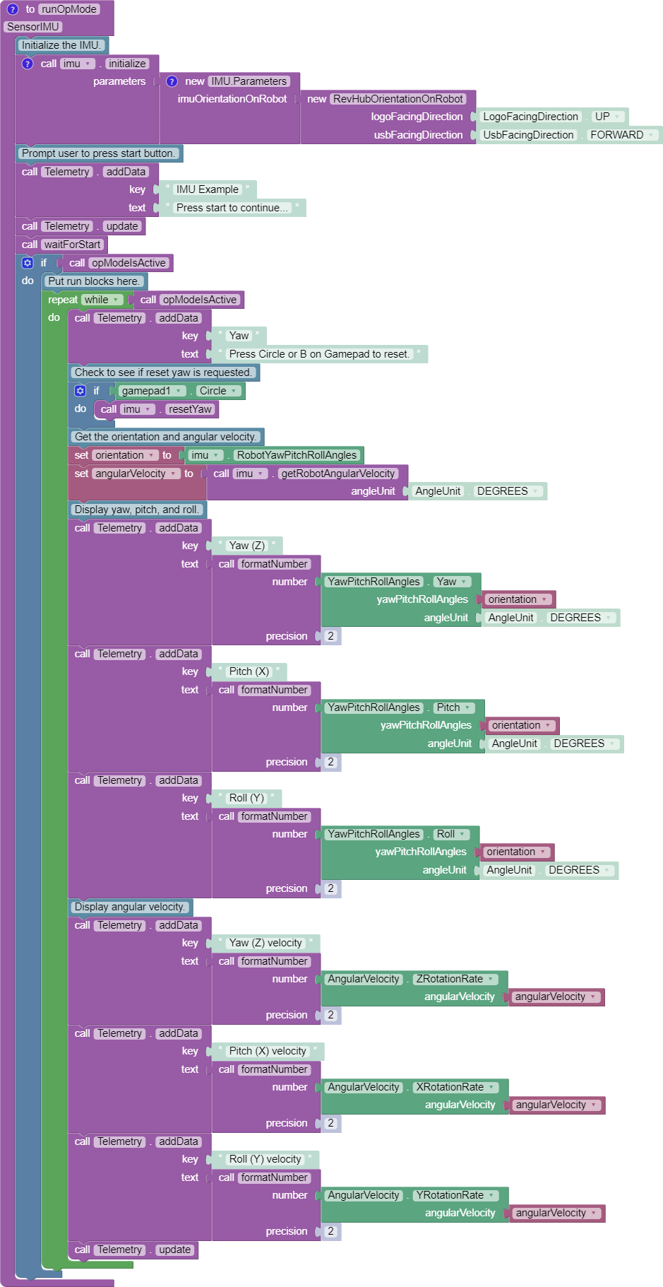
These Blocks are used here in a Repeat Loop, to display the angles on the Driver Station:

These Blocks are shown in the Sample OpMode called SensorIMU.
In Java, create an object to receive the IMU angles:
YawPitchRollAngles robotOrientation;
robotOrientation = imu.getRobotYawPitchRollAngles();
Now use these simple methods to extract each angle (Java type double) from the object you just created:
robotOrientation.getYaw(AngleUnit.DEGREES)
robotOrientation.getPitch(AngleUnit.DEGREES)
robotOrientation.getRoll(AngleUnit.DEGREES)
Note that the robot's orientation is described here intrinsically; the axes move with each rotation. Here's an example from the Javadocs:
As an example, if the yaw is 30 degrees, the pitch is 40 degrees, and the roll is 10 degrees, that means that you would reach the described orientation by first rotating a robot 30 degrees counter-clockwise from the starting point, with all wheels continuing to touch the ground (rotation around the Z axis). Then, you make your robot point 40 degrees upward (rotate it 40 degrees around the X axis). Because the X axis moved with the robot, the pitch is not affected by the yaw value. Then from that position, the robot is tilted 10 degrees to the right, around the newly positioned Y axis, to produce the actual position of the robot.
Again, the IMU output results are given in the Robot Coordinate System, or Robot axes. Only for a non-Orthogonal orientation, Hub axes were used temporarily for input parameters, describing the Hub's rotation to achieve its mounted orientation.
As an alternative to the YawPitchRollAngles class, the FTC SDK also provides a more flexible Orientation class. This allows you to specify a custom order of axis rotations, and a choice of intrinsic or extrinsic axes.
Again, IMU angles are provided in the range of -180 to +180 degrees (or from -Pi to +Pi radians).
As before, first create an object (Blocks Variable) containing the array of orientation values (from the Blocks Sensors / IMU palette):

Notice the axes order of XYZ, different than the ZXY order used by the YawPitchRollAngles class.
Then extract the specific axis rotations you want, from the Blocks Utilities / Orientation palette:

Here's an equivalent sequence in Java:
Orientation myRobotOrientation;
myRobotOrientation = imu_IMU.getRobotOrientation(AxesReference.INTRINSIC, AxesOrder.XYZ, AngleUnit.DEGREES);
Then read or display the desired values (Java type float):
myRobotOrientation.firstAngle
myRobotOrientation.secondAngle
myRobotOrientation.thirdAngle
Pay close attention to the selection of axes order, which greatly affects the IMU results. If you care mostly about Heading (Yaw), choose an axes order that starts with Z.
The FTC SDK also provides values for angular velocity, the rate of change (degrees or radians per second) for Roll, Pitch or Yaw.
As before, first create an object (Blocks Variable) containing the array of angular velocity values (from the Blocks Sensors / IMU palette):

Then extract the specific axis rotations you want, from the Blocks Utilities / AngularVelocity palette:

These Blocks are shown in the Sample OpMode called SensorIMU.
Here's an equivalent sequence in Java:
AngularVelocity myRobotAngularVelocity;
myRobotAngularVelocity = imu.getRobotAngularVelocity(AngleUnit.DEGREES);
Then read or display these values (Java type float) from the object you just created:
myRobotAngularVelocity.zRotationRate
myRobotAngularVelocity.xRotationRate
myRobotAngularVelocity.yRotationRate
These are also shown in each of the Java Sample OpModes listed in a section below.
It can be useful to reset the Heading (or Yaw or Z-angle) to zero, at one or more places in your OpMode.
In FTC Blocks, this optional command is simple:

Likewise in Java:
imu.resetYaw();It's safest to reset Yaw only when the robot has not significantly deviated from a flat/horizontal orientation.
This command assumes the Hub's actual orientation was correctly described with Orthogonal, Angles or Quaternion parameters.
In other words, a non-Orthogonal Hub moved away from its parameter-defined orientation, may not give reliable results for Heading/Yaw or resetYaw(), even after the robot has returned to its original defined orientation.
An exception, or loophole, is that "reset" Heading/Yaw values might still be valid if the Hub is actually mounted in an incorrectly described Orthogonal orientation, and the robot remains level. This may benefit a rookie team that overlooked the IMU Parameters or moved the Hub to a different Orthogonal position, still relying only on Heading. This resetYaw() exception does not apply to angular velocity for Yaw (Z-axis).
Here's the official FTC Javadocs description for resetYaw():
Resets the robot's yaw angle to 0. After calling this method, the reported orientation will be relative to the robot's position when this method is called, as if the robot was perfectly level right now. That is to say, the pitch and yaw will be ignored when this method is called.
The Javadocs' statement 'resets to 0' should be read in the context of the previous discussion. In certain off-axis Hub orientations, a reset Yaw value might not actually display as zero.
If resetYaw() does not meet your needs, other code-based choices (possibly less effective) include:
-
'Save & Subtract' to establish the current Heading as a new "zero" baseline for further navigation
-
use the original Heading for the entire match, using only absolute (global) targets
For all choices, be aware of "gyro drift". Most electronic IMUs give slowly shifting Z-angle results over time, for various reasons. Although the Pitch and Roll axes can use gravity's direction to correct for drift, Yaw (Heading or Z-angle) cannot.
The SDK 8.1.1 contains Sample OpModes demonstrating the above. In FTC Blocks, a simple example is called SensorIMU.

Here's an image and the .BLK file of this Sample OpMode.
In Java, three Sample OpModes demonstrate the new universal IMU interface:
-
ConceptExploringIMUOrientation.java provides a tool to experiment with setting your Hub orientation on the robot
-
SensorIMUOrthogonal.java shows how to define your Hub orientation on the robot, for simple orthogonal (90 degree) mounting
-
SensorIMUNonOrthogonal.java shows how to define (with the Angles method) your Hub orientation on the robot for a non-orthogonal orientation
These three Java samples include extensive comments describing the IMU interface, consistent with this tutorial. In particular, SensorIMUNonOrthogonal.java describes three helpful examples.
Advanced programmers are invited to browse the FTC Javadocs documentation (API), particularly in:
The new universal IMU features for SDK 8.1.1 are:
-
IMU(interface) -
ImuOrientationOnRobot(parameter field) -
YawPitchRollAngles(class) -
RevHubOrientationOnRobot(class)
The Javadocs describe other IMU methods and variables not covered in this basic tutorial.
The FTC SDK 8.1.1 provides a universal interface that supports both the BHI260AP and BNO055 IMU. This basic tutorial introduced some new features:
-
robot configuration allows selection of IMU type
-
three ways to specify Hub mounting orientation on the robot
-
new Blocks and Java methods to read data from both IMU types
Teams using the new Control Hub IMU must use the new SDK 8.1.1.
Updating to SDK 8.1 or 8.1.1 is optional for POWERPLAY, if you are not planning to use the new Control Hub IMU.
However all teams are encouraged to begin using the universal IMU classes and methods for new Blocks and Java code, and consider migrating existing code.
Questions, comments and corrections to westsiderobotics@verizon.net
.


- Control Hub
- Robot Controller (RC)
- Driver Station (DS)
- Two Expansion Hubs
- Updating FTC Software - new!
-
TensorFlow 2023-2024