Autonomy Starter Project - umrover/mrover-ros GitHub Wiki
Welcome to the autonomy starter project tutorial! In this tutorial, you will write code for all three subsystems encompassed by autonomy: perception, navigation, and localization. You will then put them all together in order to complete a task with a simulated rover. The goal is to familiarize yourself with what type of problems we tackle and how to do that with our codebase.
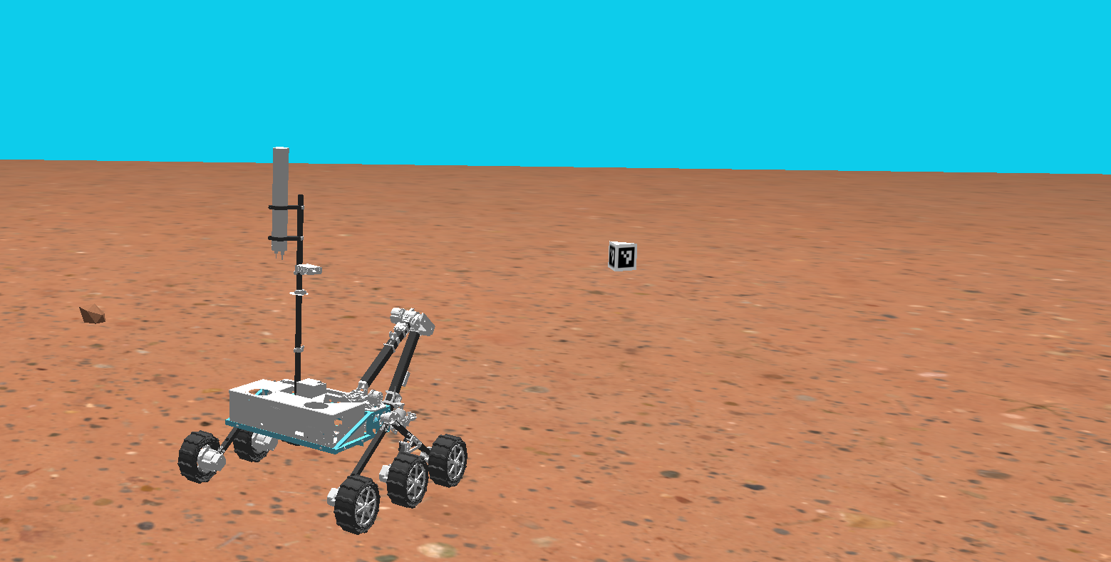
When you complete the project you will have a rover that uses its localization system to navigate to a set waypoint and then uses its perception system to drive it to a tag, here is an example of a working solution (click the image below, it's a link):
FAQ: https://github.com/umrover/mrover-ros/discussions/165
From ~/catkin_ws/src/mrover:
Follow the setup instructions here to setup up the codebase. Note the following folder ./starter_project, this is where the majority of the work will be done.
Make sure you read the "Overview" of the perception page before working on this part of the project. Note that this is the overall Wiki page for our non starter project code and there is one specific to the starter project later in this subsection.
For perception, you will write a ROS node that uses camera data to detect ArUco tags using OpenCV, a popular computer vision library. Navigation will read this data in order to align the rover with it.
- Image data:
ImageConstPtrmessages from image transport published to thecamera/left/imagetopic
- Tag center in camera space, an approximation for rover → tag distance: Custom message published to
tag
Now proceed to perception-specific page for the implementation! You will notice a common theme on MRover is breaking down problems into inputs and outputs then providing more details on specifics in separate locations.
Make sure you read the "GPS", "IMU", "GPS Linearization", and "Guide to Localization Frames" sections from the Localization page before working on this part of the project (RTK is beyond the scope of our starter project but recommended).
For localization, you will write a ROS node that uses GPS and IMU data to figure out where the rover is, and then publish this information as a transform in the TF tree. Here is the interface your node should follow:
- GPS data: NavSatFix messages published to the
/gps/fixtopic - IMU data: Imu messages published to the
/imu/imu_onlytopic
- Rover pose: transform in meters published to TF tree
You should start by subscribing to the GPS and IMU sensor data provided as inputs. To do this, you will have to create two rospy.Subscriber objects. The python syntax for creating a subscriber looks like this:
rospy.Subscriber(topic_name, msg_type, callback_function)What this effectively does is tell ROS that your node should listen to, or "subscribe" to a ros topic topic_name that carries msg_type messages, and whenever you receive one, callback_function should be called. The callback function headers for gps_callback and imu_callback have already been provided for you, so make sure to use them when creating the subscribers.
In your callback functions, all you should do for now is print out the data you're receiving (which comes in the form of the msg argument to the function), that way you can make sure you're successfully getting the data. For more help on writing a subscriber, read this ROS tutorial on writing a Publisher/Subscriber Node.
In order to run your node along with the rest of the starter project, you will need to add it to the starter project launch file. Open starter_project.launch in the launch folder and uncomment the line declaring a node in the localization section. Notice the syntax for launching a node:
<node name="localization" pkg="mrover" type="localization.py" />As you can see, we are launching a node that we have named "localization", is from the mrover package, and has an executable localization.py which is what will actually get run.
Once this line is uncommented, you should be able to launch the file with
roslaunch mrover starter_project.launchNow that you have your data, you need to use it to figure out where the rover is; Let's start with GPS. The GPS latitude and longitude coordinates tell us where we are in spherical earth coordinates, but what we really want are cartesian (x, y, z) coordinates in meters. Because our rover is driving in an area that is tiny relative to the size of the earth, we can approximate the area the rover drives in as a flat plane tangent to the surface of the earth:

For this to work, we will need to define a point on the earth in (latitude, longitude) coordinates where the center of our tangent plane will be; this point will be called the reference point. As long as this reference point is
close (within a few hundred miles probably) to where the rover is going to be, this tangent plane will be a pretty good approximation. For this project we will simulate the rover as driving near ann arbor. Use the reference latitude and longitude found in mrover/rover_description/rover_gazebo_plugins.xacro or mrover/urdf/rover/rover_gazebo_plugins.xacro

To convert our spherical coordinates to cartesian coordinates, you can imagine zooming in on the tangent plane. We can find our latitude and longitude "distances" by subtracting our reference coordinates from our spherical coordinates, and then we just need to convert the units of those distances from degrees to meters. We are going to pretend the earth is a perfect sphere to make things simple.
For north/south latitude distance, which will become our x coordinate, this is pretty simple. If the earth is a perfect sphere, then each meridian (vertical band) around the earth has the same circumference as the equator. Since we know the circumference of the earth at the equator (6371000 meters), we know that 1 degree of latitude is equal to the circumference divided by 360.
For east/west longitude distance, which will become our y coordinate, things get a little trickier because each horizontal band around the earth does not have the same circumference. To account for this, we have to scale the circumference with the cosine of latitude (think about why this makes sense). Then we can use the same equation as we used for latitude. Here are the equations you need to implement in code:

This equation assumes that our reference heading is 0 degrees (North), but in the simulator, it is actually 90 degrees so you will need to rotate the point by 90 degrees. You should implement this conversion in the spherical_to_cartesian function. This is a static method, so it should be called with the class name instead of an object name: Localization.spherical_to_cartesian(). Read the function docstring for more details. Make sure to use numpy for the trig functions (np.sin(), np.cos(), etc) and make sure to convert between radians and degrees when necessary (check the ROS message definitions and function docstrings when in doubt - GPS coordinates are given to you in degrees, what do the trig functions from numpy (and python math) operate on?. For this simple starter project, we don't care about the Z coordinate, so just set it to zero. Once you are done, make sure to test your code by printing out your cartesian coordinates. You can do this by using the rospy.loginfo(msg) function.
You don't have to do any conversions for the IMU data, since it will give you an orientation quaternion, which is exactly what you need in order to make an SE3.
At the end of each callback function, you will now have either [x,y,z] coordinates or an orientation quaternion. How do we give this data to the rest of the autonomy system? It's pretty simple, there are just a couple steps.
First, we have to update our classes global state. Inside of our Localization class, we can keep track of our rover's pose using the SE3 self.pose. For this beginner project, we will go with a simple update policy, where we want to update our global state every time we get any new sensor data. This means we want to update self.pose in both callback functions, and in each one we only want to change the data that we know. So in the GPS callback, you will need to set self.pose equal to a new SE3 using your new [x, y, z] position and the existing orientation data in self.pose. The GPS callback function is called whenever the localization node receives a message on the /gps topic that we subscribed to in the init function. Conversely, in the IMU callback, you need to set self.pose equal to a new SE3 with the same position data and your new orientation data.
Once you've done that, you can simply call the publish_to_tf_tree() method on your SE3. As the name implies, this will publish your pose to the TF tree. Since this is the pose of the base of the rover relative to the map, you should specify your parent frame as "map" and your child frame as "base_link" (this is the name used for the base of the rover).
For navigation, you will write a ROS node that uses the outputs of the localization and perception nodes in order to command the rover towards the point and then the AR tag. In the end, the rover will turn towards a given point (5.5 meters, 2 meters) and then drive towards it until it is in a set threshold. Once there, the rover should be able to see an AR tag. The rover will turn towards the AR tag so it is directly aligned, then drive forward until it is in a set threshold.
It is often easiest to think in terms of inputs and outputs so here are the inputs and outputs for this node:
- Rover pose (the rover’s position and orientation in space): transform from TF tree
- Tag message published from the perception node (from channel
tag)
- Velocity data: Twist message
We've created the base structure of the project for you in order to mimic the structure of our current code. We recognize that there are other ways to do this, and probably ways to do the same thing in less code, however we want you to gain an understanding of smach and the general way we structure code in the navigation subsystem. With that said, here is an outline of each subcomponent of the navigation system and what it is responsible for as well as what you will need to do in each one in order to complete the project. Start by implementing the underlying infrastructure required for the navigation node to be able to properly read its inputs and send its outputs. Then write the logic for each of the two states that you will need for the project.
The files you need to edit are under mrover/starter_project/autonomy/src/navigation.
In context.py
The goal of this class is to provide access to an interface for reading and writing information regarding the rover's environment and the rover itself. It contains objects of Rover and Environment both of which you will need to implement various functions in. It also contains the ROS publisher and subscriber objects that you will need to use to listen to and send the messages for this node.
In context.py
Lets start by implementing the Rover class. The rover object (accessed through the context object) is responsible for the interface for all things related to the rover. In our case, this will mean we need to implement three functions:
get_pose(self) -> Optional[SE3]
Here we will need to fill in the code so that the function returns an SE3 object that represents where the rover is in the world. For more information about SE3s and what they are checkout this wikipage. Additionally, read over the docstrings within mrover/starter_project/autonomy/src/util/SE3.py to see the full SE3 interface and understand what the interface is.
Once you do that, you're going to want to use the SE3.from_tf_tree function in order to get the SE3 that represents the rover's pose. This function is found in the SE3.py file. We have imported this class into the context file. The function’s parameters include:
tf_buffer: the tf buffer used to query the TF tree
parent_frame: the parent frame of the desired transform
child_frame: the child frame of the desired transform
Note that the tf_buffer has already been created for you and is owned by the Context object which is called ctx in the rover class. Once again, since this is the pose of the base of the rover relative to the map, you should specify your parent frame as "map" and your child frame as "base_link" (this is the name used for the base of the rover).
send_drive_command(self, twist: Twist)
Here we will need to fill in the code so that the function publishes a twist message using the velocity command publisher object that is also already a member of the context (vel_cmd_publisher). This is of type rospy.Publisher so you will need to use the function publish() on this publisher. Learn more about this here in section 1.2.
send_drive_stop(self)
Here we will need to fill in the function so that it stops the rover when run (hint #1: use send_drive_command()) (hint #2: Twist() initializes velocities to be 0 in its message).
In context.py
The environment class is similar to the rover class except instead of providing an interface to things going on on the rover, it provides an interface to things going on in the environment around the rover. For us this means implementing two functions:
receive_fid_data(self, message : StarterProjectTag)
This function is the callback function that we have set up for you such that it will be invoked every time we receive an AR tag position message. You will need to update a member variable in the Environment class to hold the StarterProjectTag message passed to this function (hint: fid stands for fiducial, which is the AR tag in this case).
get_fid_data(self) -> Optional[StarterProjectTag]
This function should return either None or your AR tag position message. It should return None if you don't know where the tag is, or it should return the most recent ROS message regarding the AR tag's position if you do know where the tag is.
HINT: Use the same member variable you just set in your receive_fid_data function.
Now we have finished creating the base-level interfaces that we will use to actually write the logic on top! Basically, all of the interaction with the outside world is complete, we now will use the abstractions we've created to code the logic of our state machine. Let's take a look at how we structure single states and build the states that we will need. After that, we will hook our states into the greater state machine and we will have completed the project!
First of all, what is a state? Please read this page to learn what a state is and checkout this page for full smach documentation.
See state.py
We have provided a Base State (the same one that is used in our current competition code) to provide some useful functionality on top of the basic smach.State class. The basic idea is just to make sure that the state machine will terminate properly no matter what if a user presses ctrl-c. The main thing to takeaway from this is just that when you are creating a state in the mrover navigation node, always extend BaseState not smach.State and always override evaluate() rather than execute().
See state.py
We have also provided a Done State that represents the rover in its "Done State" because we don't want our program to just end when the rover completes, we have a state that essentially just loops and does nothing.
In drive_state.py
The goal of this state is to drive towards the set point (5.5, 2). We've created the class for you but you will need to implement the evaluate() function. We've provided a general outline in the comments of how this function might be structured and have also providing a function get_drive_command() imported from drive.py that you can use to do some of the math in this step for you. The function should return a string "outcome" depending on what state it needs to transition to next.
You will also need to add those outcomes to the add_outcomes parameter that is passed to the parent constructor.
Hint: Use the functions from context.rover we've already written
In tag_seek.py
The goal of this state is to drive towards the AR tag after arriving at the set point (5.5, 2). We've created the class for you but just like the Drive State you will need to implement the evaluate() function. This will be a bit trickier as you don't actually have a pose to drive to you just have the same general measurements regarding angular and distance offsets that you calculated earlier.
You can get information about how close the rover is to the tag by using the function get_fid_data in context.env. You want the rover to be within a certain distance (DISTANCE_TOLERANCE) from the tag, and face the tag within a certain angular distance (ANUGLAR_TOLERANCE), to be able to transition to the Done state with outcome “success”. We have set these tolerances to be DISTANCE_TOLERANCE = 0.99, ANUGLAR_TOLERANCE = 0.3. Hint: get_fid_data() returns StarterProjectTag, this includes information about how close the rover is to the tag and the measurements of where the center of the tag is in our view (x and y).
If the rover is not within the angular and distance tolerances, create a twist command and change the linear.x value and/or the angular.z value so that the rover becomes within the tolerances. Then send this twist command to the rover and stay in the TagSeekState by returning the outcome “working”.
You will also need to add those outcomes to the add_outcomes parameter that is passed to the parent constructor.
In navigation_starter_project.py
The navigation class is where the whole state machine comes together. We've already done the hard work of creating the whole state machine now we just need to put it all together. We've already added the DoneState to the state machine, and use a similar pattern for adding the TagSeek and DriveState states to the state machine.
Hint: transitions is a dictionary that maps state outcomes to the actual string of the state that the transition goes to (ex. "working": "TagSeekState").
To wrap up the navigation project, init a ROS node called "navigation" in the main function. Learn more about this here in section 1.2.
Open starter_project.world (Ctrl-P to search in VSCode) and find the following snippet:
...
<model name='waypoint_post'>
      <pose>5.5 2.0 0.5 0 0 4.71239</pose>
...
Make sure the pose is set the same as the snippet above.
Now open starter_project.launch which is in the mrover/starter_project/autonomy/launch folder. Make sure the lines declaring a node in the localization and perception sections are uncommented, while the line declaring a node in the navigation section is commented.
To run the rover in the simulator:
- In your terminal run
roslaunch mrover starter_project.launchto open the simulator, you should see the rover not moving in Gazebo. - In a new terminal run
rosrun mrover visualizer.pyso you can monitor which state the rover once you start it (you won’t see the visualizer until you run the next step). - In a new terminal run
rosrun mrover navigation_starter_project.pyto start the rover. Watch it move to (5.5, 2) while being in the DriveState, transition to TagSeekState, see the tag, and finally reach the tag and move to the DoneState.

Congrats! You've finished the autonomy starter project!