Installation - tomaskovacik/audi_concert1_chorus1_volume_fix GitHub Wiki
To remove upper metal cover use screwdriver to pry it out at corners:

Then using Torx T-8 bit remove four screws at these locations:

After screws are removed, gently lift the circuit board on the left side of the deck

Gently lift the left side of the tape deck an move it slightly to the left, exposing flat flex cable from heads, then remove the brown board with flex cable which goes to the mainboard:

Desolder two resistors marked on next picture (I tape them inside the radio, In case I will need them for reverting to original state)

Solder two wires from the module as shown in this picture, wires are not always the same colour as shown, trace wires to holes on the module. Holes are marked on the upper side of the module (SDA and SCL). The wire from SDA must go to lower pad and the wire form SCL to the upper pad, they cannot be swapped!.
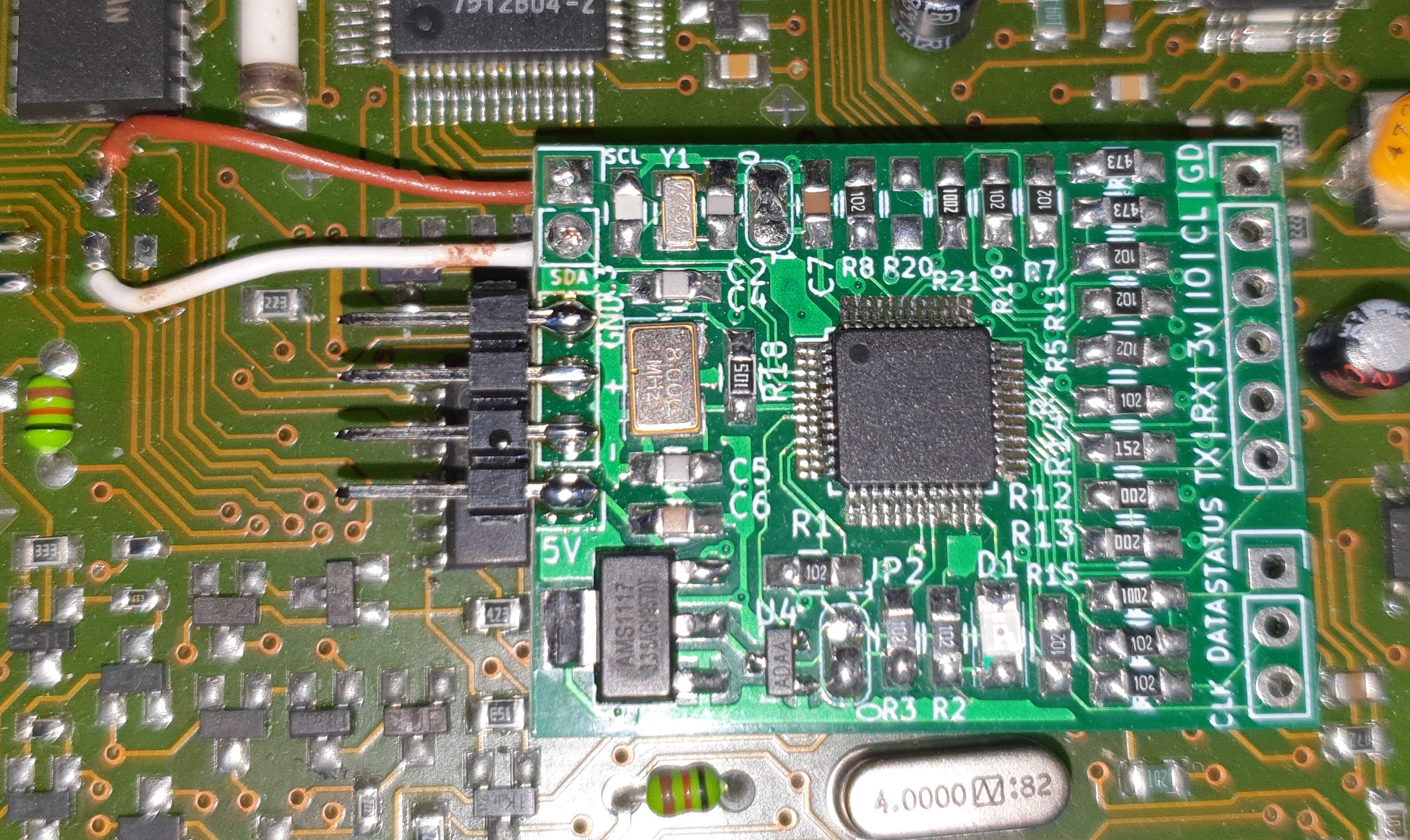
After the wires are connected, press module on Motorola MCU, the module must be installed almost all the way down to the mainboard.
After powering radio with 12V, LED on the module will light up, if not then module did not have 5V supply from main MCU, check voltages based on this picture.

If there is no 5V then 3.3V will not be present also. Missing 5V supply can be 2 whings: bad contact on 5V pin or on the ground pin, try pushing the module down more. If it pops out, put layers of cardboard on the module and then screw down tape deck, which will hold module down and you can test it. Another problem can be corroded pins on main MCU, clean them. Another problem can be solder or other debris on pins, also cleaning Motorola MCU will solve the problem.