Assemble guide - tomaskovacik/audi_concert1_chorus1_volume_fix GitHub Wiki
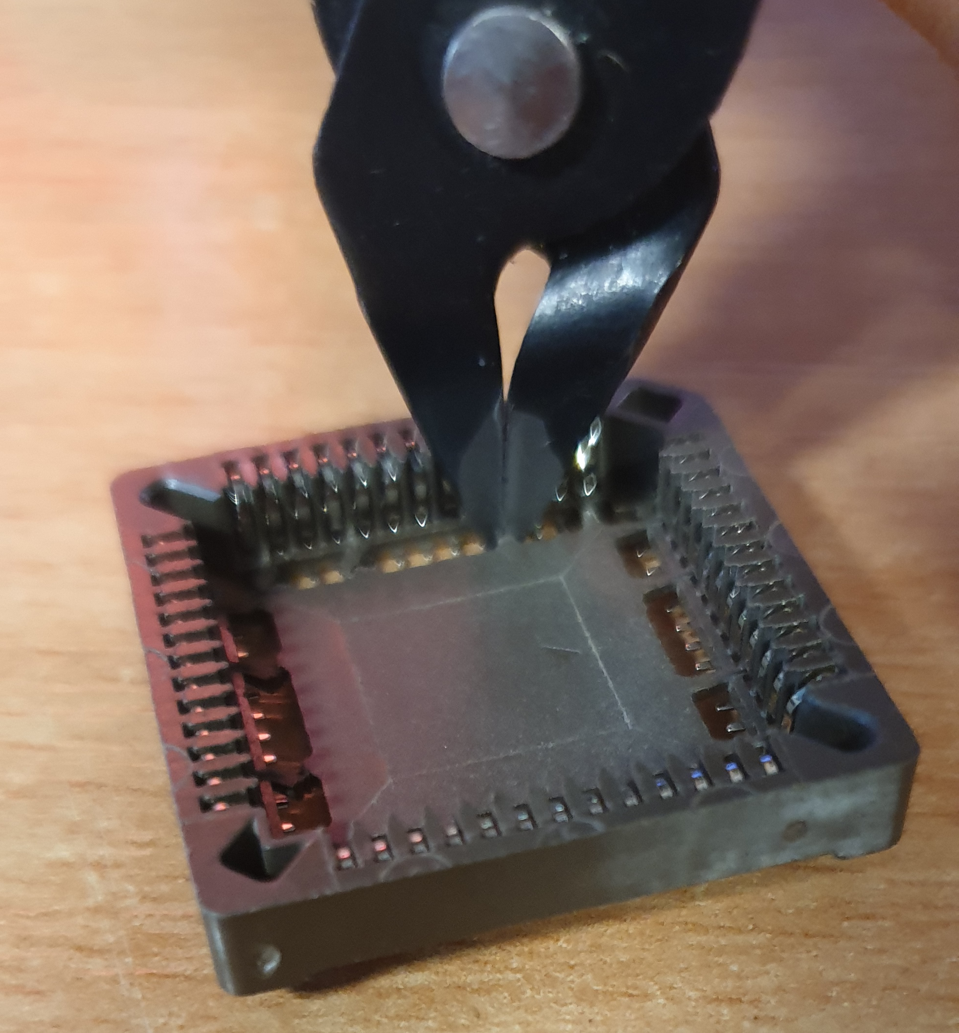
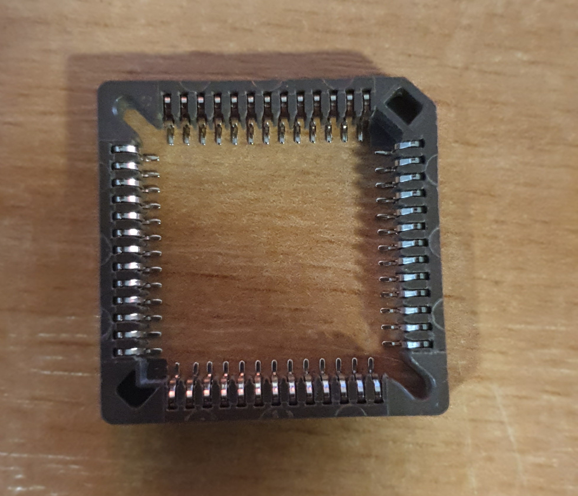
PLCC52 socket
For best contact with motorola mcu on main board of radio, inner part of PLCC socket need to be cut out.
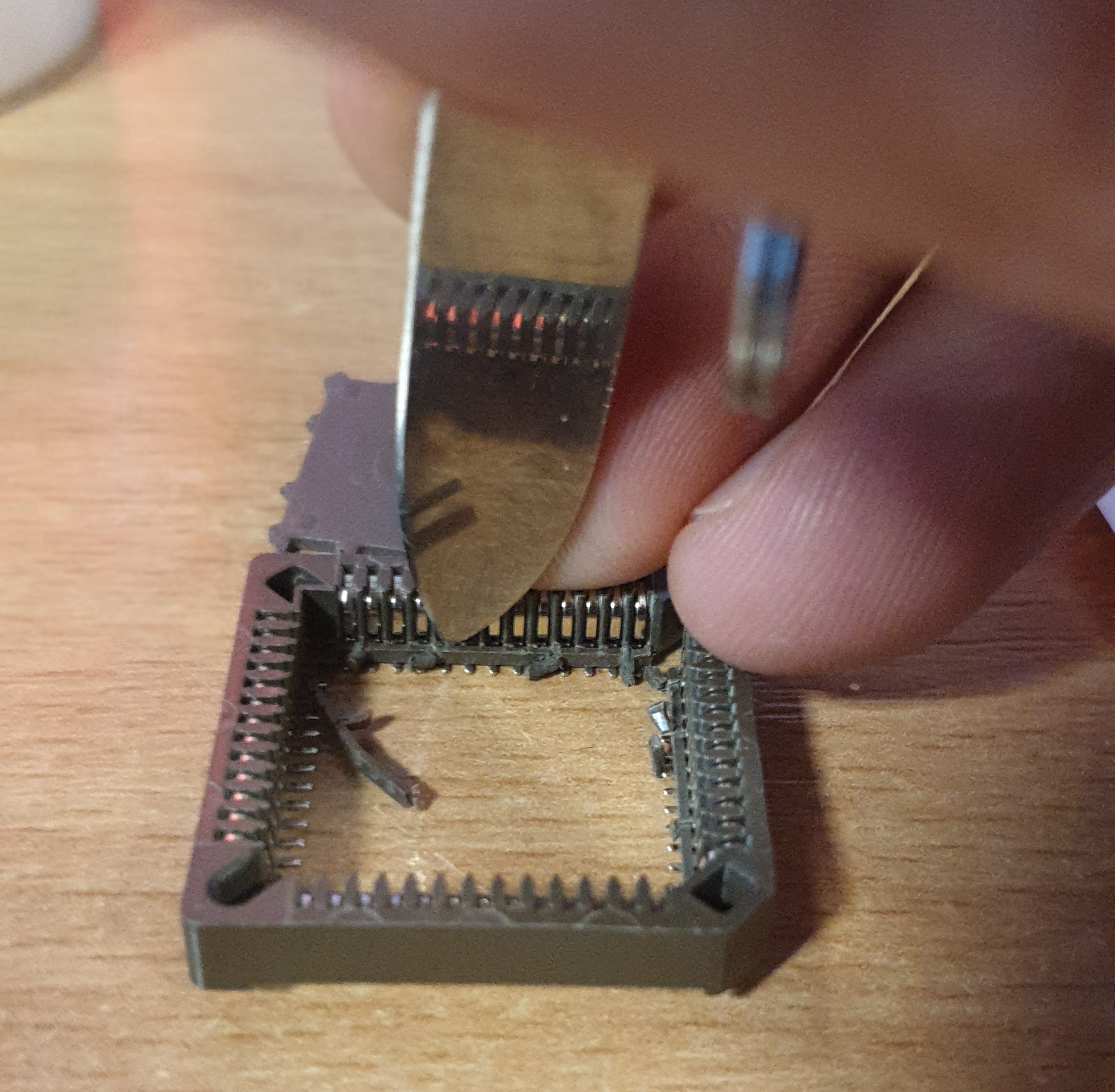
- cut small bridges between inner and outer part using small side cutters and cutout inner big plastic part of socket:
- using a knife or similar tool to break plastic bridges over metal pins, the tool has to be flat, so it is supported on plastic part of socket not on the springy part of the pins, this will cause deformation and later bad contact with motorola mcu leading to not working unit!
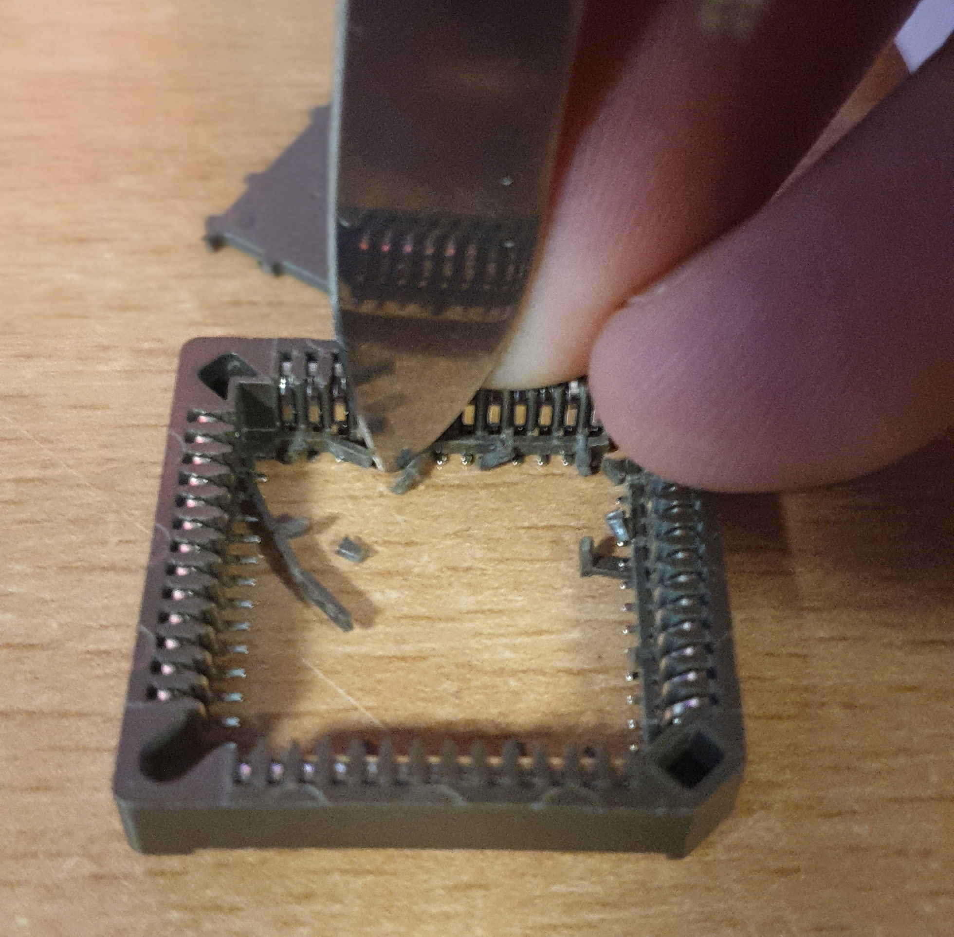
- finished modified socket, ready to be soldered
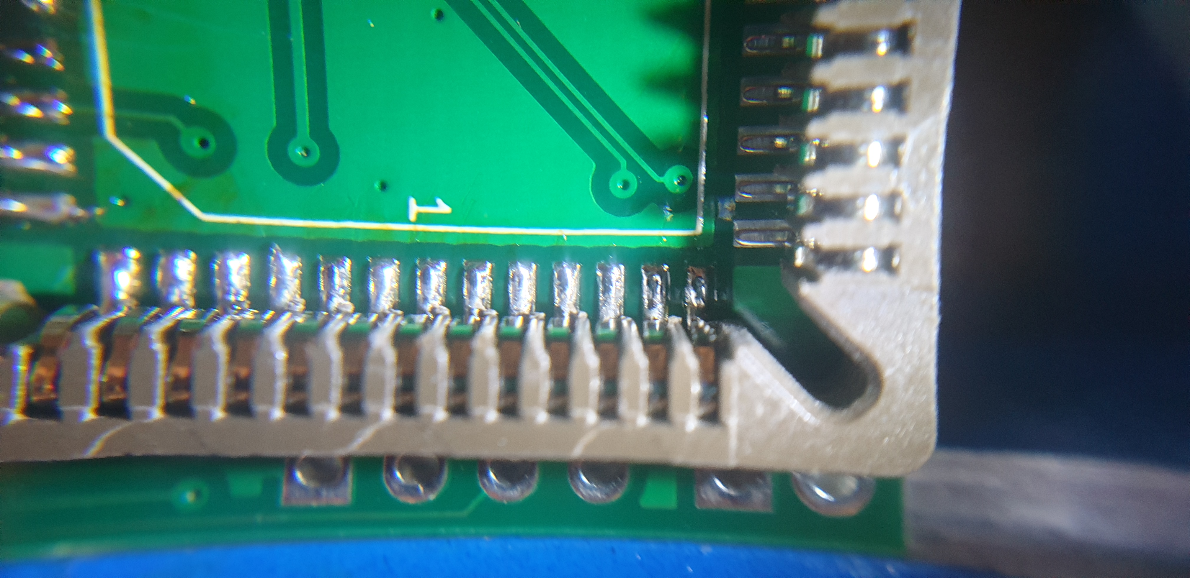
- start with one pin of socket, then on the opposite side solder second one, make sure the pins are aligned with PCB pads.
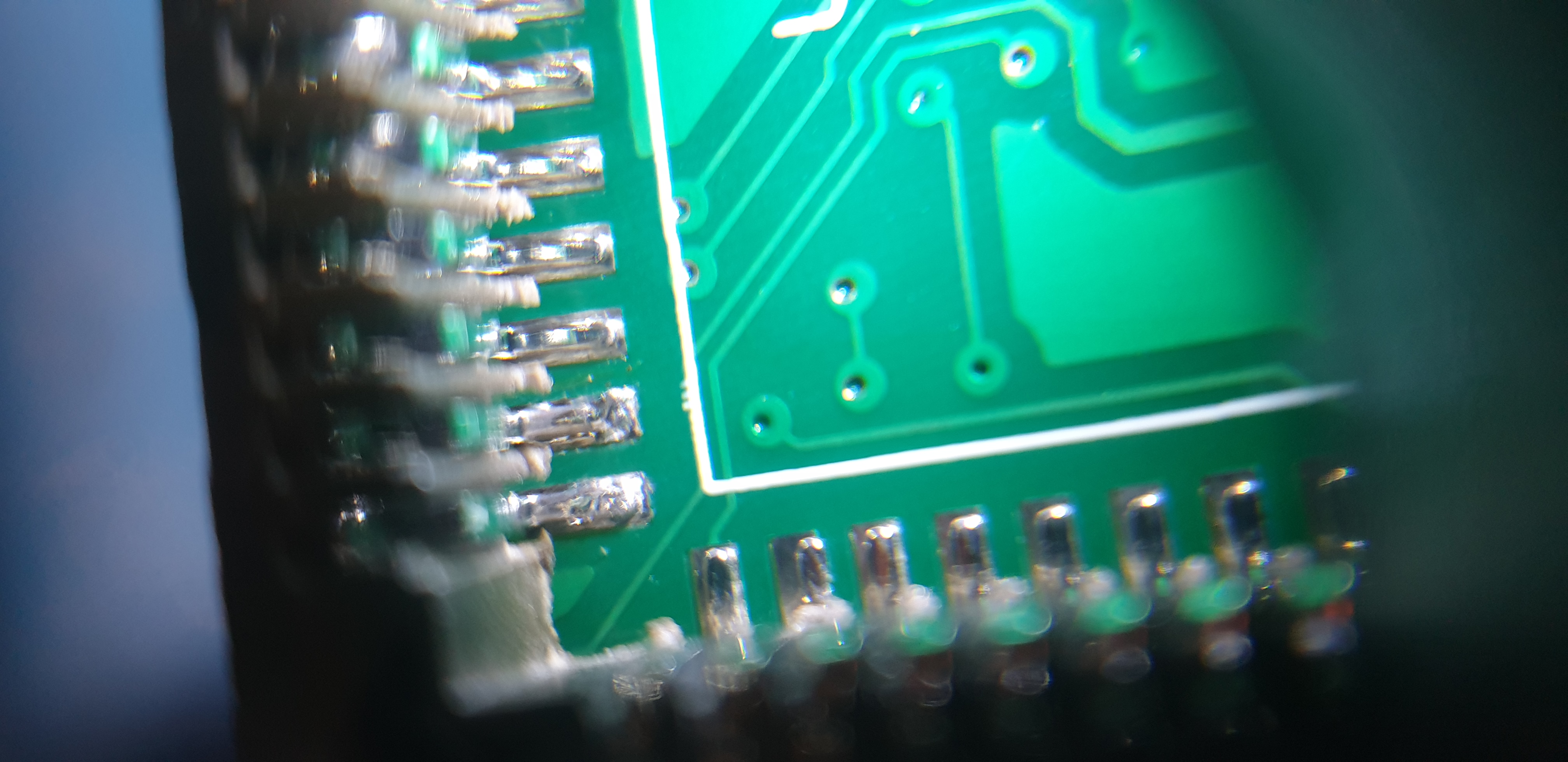
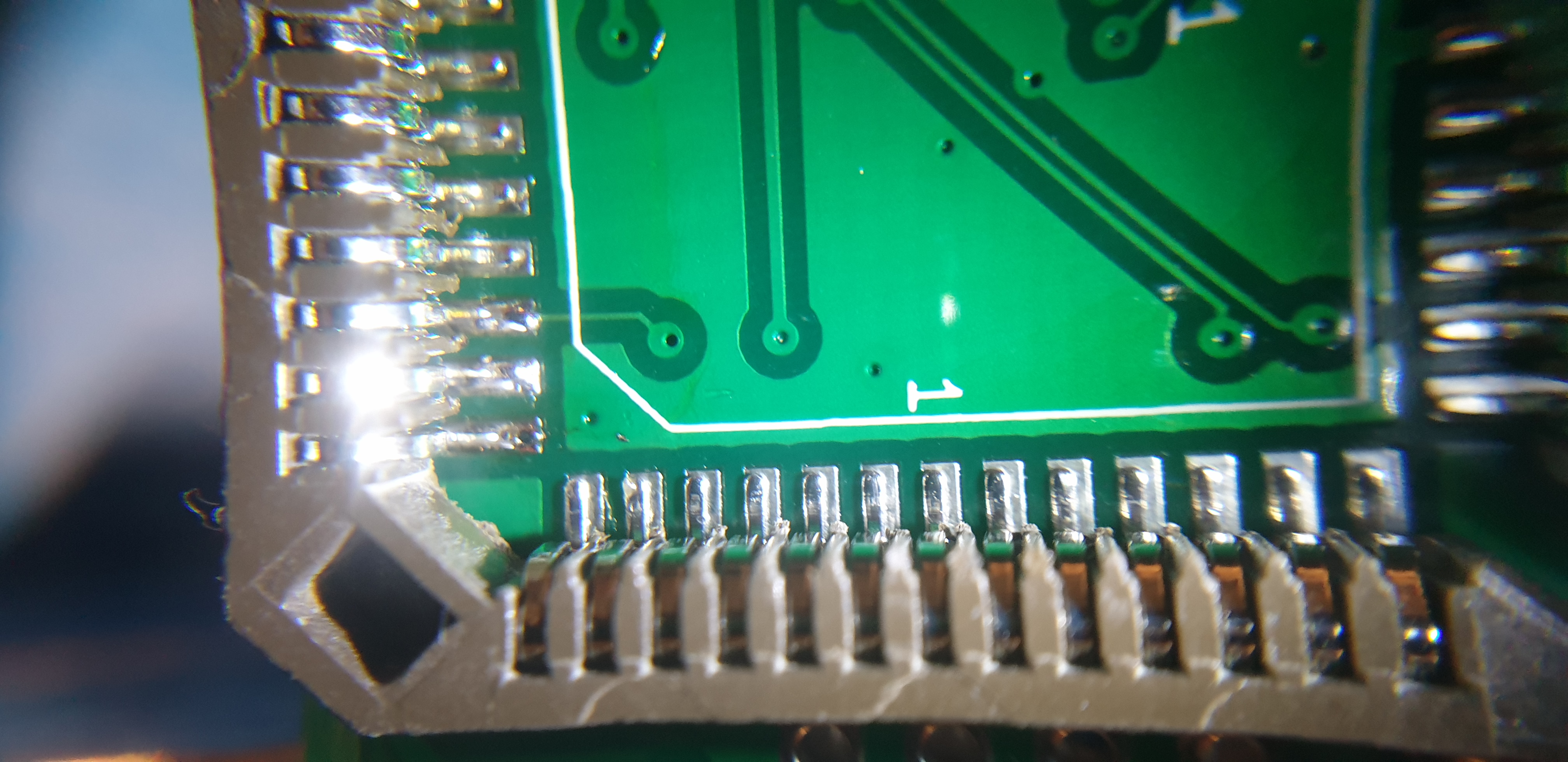
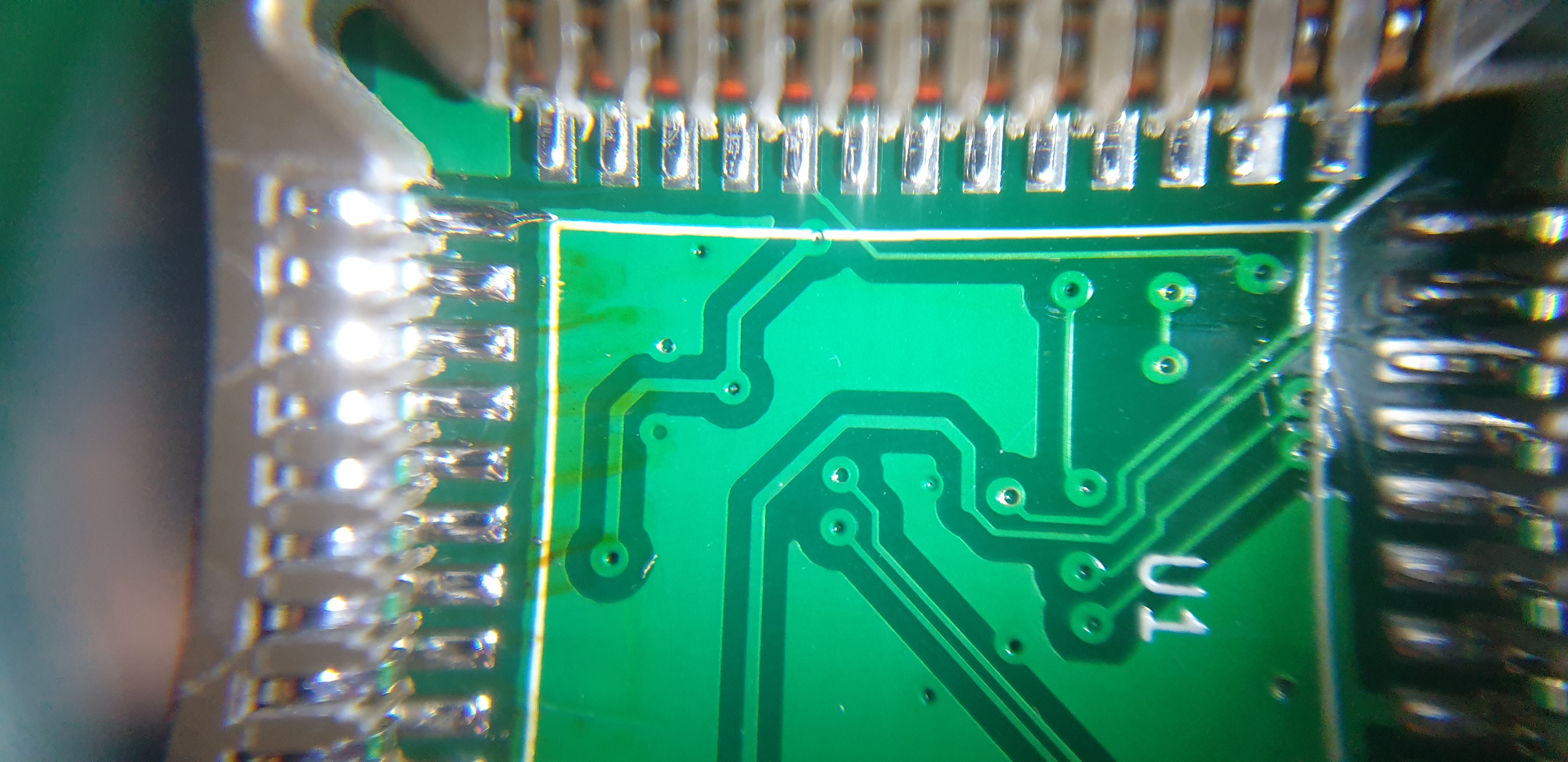
- solder all 52 pins, inspect soldering for solder bridges!
SMD components
- solder other SMD components with your preferred method:
- crystals using hot-air, as they have pads only on the bottom, so they are difficult to solder using the soldering iron. (If you have the kit from my tindie store crystal are already solder on PCB).
- STM32 mcu
- resistors, capacitors, etc
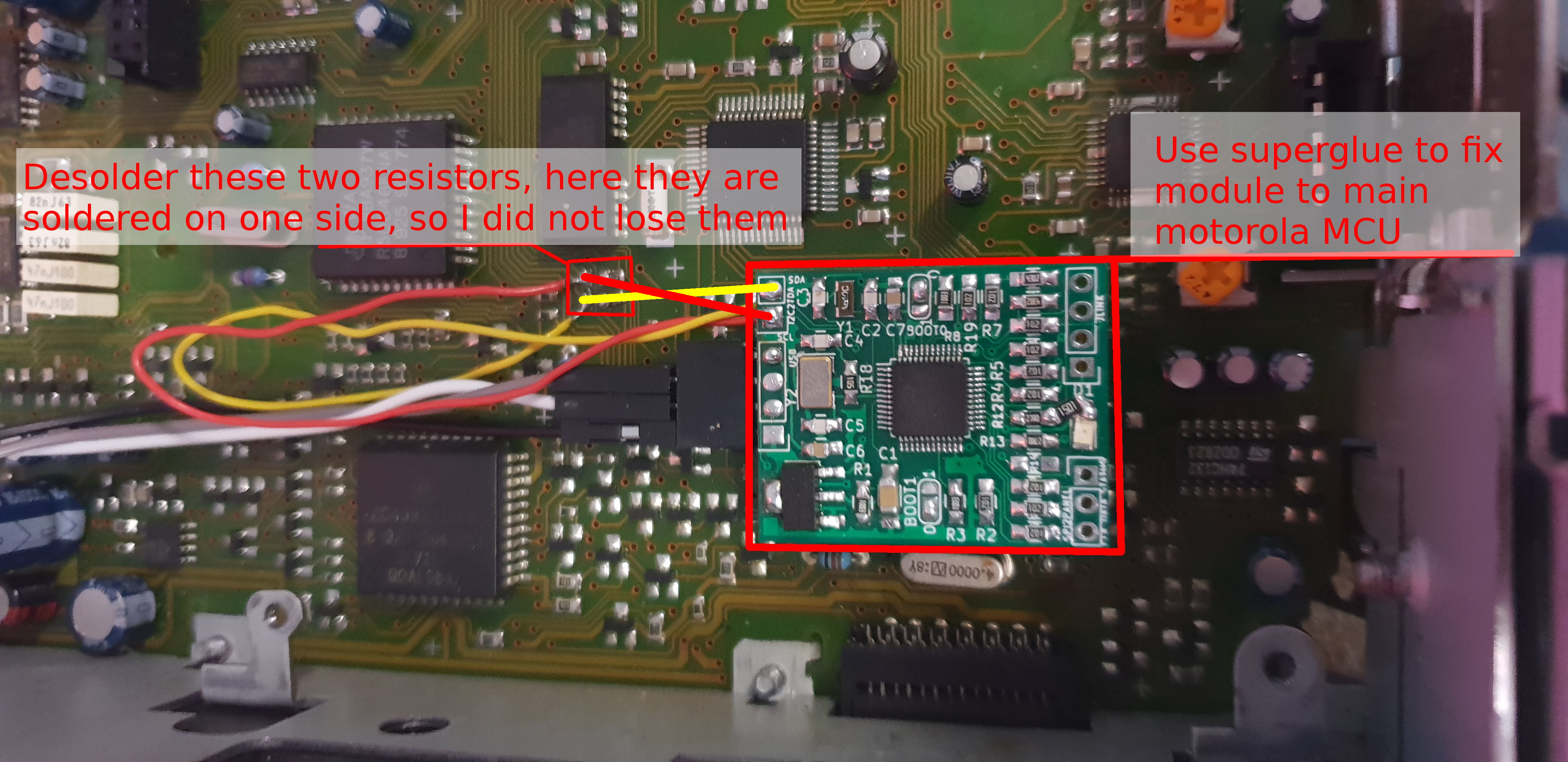
- Two wires for connection to TDA sound processor
For placement refer to assemble plan:

Bypass of the I2C lines
Two wires for connection to TDA sound processor (yellow and red ones), resistors on the position where the wires will be solders to main PCB have to be removed. Then solder wires to the outside pads where resistors where connected. When the module is inserted on the main MCU then the wire from lower pin (named SCL) goes to the upper outer pad on the main PCB and the wire from the upper hole named SCA goes to the lower outer pad. Do not forget resistors must be removed!