Geometry - subtilitas/Wingdesigner GitHub Wiki
Deutsch: Geometrie
| Convention | Value |
|---|---|
| Lengths | millimetres (mm) |
| Angles | degrees (°); twist positive = leading edge up |
| Axes | x chordwise, positive towards the trailing edge; y spanwise, positive towards the right tip; z up |
| Computed geometry | right half wing (y ≥ 0); the left half is its mirror image at the plane y = 0 |
| Curves and surfaces | NURBS (Non-Uniform Rational B-Spline) with all weights 1, i.e. non-rational B-splines |
| Algorithm numbers (A2.1 …) and equation numbers | Piegl and Tiller, The NURBS Book, 2nd edition, Springer 1997 |
| Messages | The messages quoted on this page are the English texts of the app. The German interface writes them in German (Geometrie). The checks, limits and results are the same in both languages. |
| Symbol | Meaning |
|---|---|
| LE, TE | leading edge, trailing edge (used as subscripts: x_LE, x_TE) |
| N | number of chord intervals per surface (N + 1 stations per surface, LE and TE included): Settings > Chordwise stations per surface, default 60, range 16 to 200 |
| K | spanwise stations per panel: Settings > Spanwise stations per panel with guides, smooth mode or mitred linear panels, default 8, range 3 to 40; the grid limit of section 3.2 can reduce it |
| c | chord in mm |
| f_pivot | twist pivot as a fraction of the chord: Settings > Twist pivot (fraction of chord), default 0.25, range 0 to 1 |
| δ | dihedral of a panel: atan2(z_(i+1) − z_i, y_(i+1) − y_i) of its two section positions, in degrees. The section planes use the panel angle instead, which a section can store (section 3.8) |
| φ | roll of a section plane about the x axis (section 3.8); φ = 0 is the plane y = const |
| m | thickness stretch of a placed airfoil (section 3.8); 1 in a vertical plane |
| n | index of the last point of a point list (points 0 … n) |
| p | degree of a curve |
| u | surface parameter around the profile: 0 upper TE, u_LE leading edge, 1 lower TE |
| v | surface parameter along the span: 0 root, 1 tip |
| Panel | span interval between two neighbouring sections |
| Station | one placed airfoil outline at span position y; every section is a station |
Derivatives are written dx/du and d²x/du². Subscripts are point indices (Q_k, x_N) or labels (x_LE, x_norm).
| Step | Code | NURBS Book algorithms |
|---|---|---|
| 1. Airfoil to NURBS curve |
src/airfoil/geometry.js, src/geom/profile.js
|
A2.1, A2.2, A2.3, A3.1, A3.2, A9.1 |
| 2. Common chord stations |
src/geom/profile.js, src/geom/wing.js
|
A3.1 |
| 3. Spanwise stations |
src/geom/wing.js, src/geom/spanwise.js, src/geom/guide.js
|
A9.1 |
| 4. Surface |
src/geom/wing.js, src/geom/nurbs.js
|
A9.1 per row and column (equivalent to A9.4), A3.5 |
| 5. Meshes |
src/geom/mesh.js, src/geom/triangulate.js
|
A3.5 |
| 6. STEP (Standard for the Exchange of Product model data) topology | src/export/step.js |
A5.1 |
| 7. Planform statistics |
src/geom/stats.js, src/geom/wing.js (planformAt) |
– |
| 8. Foam cores | src/geom/foam.js |
A3.5 (per column curve) |
The rigid placement of the part (section 3.9, src/geom/part.js) turns the result of steps 3 and 4 for steps 5 to 7.
Input: airfoil points in Selig order (upper TE → leading edge → lower TE) that pass the sanity checks
(File Formats). A sanity-check error, a self-crossing curve (section 1.4) or an x
reversal (section 1.5) blocks the wing build; warnings do not. The sanity checks first remove
consecutive points closer than 1e-9 of the x range (info duplicates): their parameters u_k (section
1.2) can round to the same value and make the linear system singular.
- File leading edge P: the file point farthest from the TE midpoint (mean of the first and the last point). Squared distances within a relative 1e-15 of the largest count as ties; ties go to the smaller x, so every scale of the same outline picks the same point.
- Translation and uniform scaling only. The airfoil is not rotated.
c_file = x_max − x_min
x_norm = (x − x_min) / c_file
z_norm = (z − z_P)  / c_file
- Inclined airfoils: the line from P to the TE midpoint keeps its angle. Above 0.5° the sanity checks
report the warning
rotated. Twist then refers to the x axis of the file.
| Property | Value |
|---|---|
| Method | global curve interpolation through every point Q_0 … Q_n (A9.1) |
| Degree | 3 |
| Parameters | Settings > Profile parametrization: Centripetal (recommended) (default), Chord length or Uniform (eq. 9.3 to 9.6) |
| Knot vector | clamped, by averaging (eq. 9.8) |
| Linear system | band LU (lower-upper) factorization without pivoting; row k holds the p + 1 basis values of the knot span of u_k, all other entries are 0; B-spline collocation matrices are totally positive for nondecreasing parameters, so elimination without row exchanges is stable (de Boor and Pinkus 1977); decreasing parameters stop the interpolation with the error "Interpolation parameters must be nondecreasing." |
| Parameter range | u = 0 at the upper TE, u = 1 at the lower TE |
d_k = |Q_k − Q_(k−1)|^e          e = 1 (Chord length), e = 0.5 (Centripetal)
u_0 = 0,  u_k = u_(k−1) + d_k / Σ d,  u_n = 1
Uniform:  u_k = k / n
knots:    U_(j+p) = (u_j + … + u_(j+p−1)) / p,   j = 1 … n − p,   p + 1 end knots at 0 and at 1
The section origin is the minimum-x point of the curve: u_LE with dx/du(u_LE) = 0.
| Property | Value |
|---|---|
| Start value | parameter of the file point with minimum x |
| Iteration | Newton step u ← u − (dx/du) / (d²x/du²), derivatives by A2.3 and A3.2 |
| Bracket | parameters of the two neighbouring file points; a step outside the bracket becomes a bisection step on the sign of dx/du |
| Stop | |dx/du| < 1e-14, step < 1e-14, or 50 iterations |
| Fallback | if x(u_LE) is larger than x of the minimum-x file point, u_LE is the parameter of that file point |
A cubic curve can loop between file points that pass every sanity check, e.g. past the TE of a coarse file. The same test runs on each airfoil curve and on the surface rows (section 4).
| Property | Airfoil curve | Surface row |
|---|---|---|
| Curve | NURBS curve of section 1.2, normalized coordinates | row v = const of the surface S, projected to the plane of its station: x and the up direction (0, −sin φ, cos φ) of its roll φ (the x-z plane for φ = 0, section 3.8) |
| Rows tested | – | at the y of each section, halfway between 2 neighbouring sections and halfway between the 2 stations of each of the 64 widest station intervals (MAX_STATION_ROWS; every interval when there are at most 64; added stations included); other rows: the thickness checks of section 3.6 |
| Samples per knot span | per = max(1, min(256, round(4000 · L_span / L_total))); L_span = length of the control polygon of the span (p segments), L_total = sum over the non-empty knot spans | 4 |
| Samples in total | Σ per + 1, about 4001 | 4 · spans + 1 |
| Test | proper crossings of non-adjacent polyline segments; every crossing found is sized; crossings up to the tolerance do not count; the search stops after 20 crossings above the tolerance; the largest is reported | same |
| Search | grid of about √n × √n cells over n segments, each cell at least twice the median segment box in x and in y; only segments that share a cell are tested; a cell with more than 32 segments gets its own grid over the part its segments cover, at most 6 levels deep (selfIntersections in src/airfoil/geometry.js) |
same |
| Size of a crossing (mean width) | the crossing splits the polyline into 2 parts; part P = the part with the smaller bounding-box diagonal; size = area(P) / diagonal(P), area of P as a closed polygon (shoelace formula) | same |
| Tolerance | size > 5e-4 of the chord (0.05 %) is an error. Cusped closed TEs of 246 real files leave slivers of at most 1.6e-5 of the chord (0.0016 %); the loop of a coarse 9-point file measures 2.5e-3 of the chord (0.25 %). In the wing build the loop is also limited to 0.1 mm (CROSSING_LIMIT in src/geom/profile.js) at the largest chord of the sections that use the airfoil: above 200 mm chord a loop wider than 0.1 mm is an error, and the message adds "the loop is … mm wide at … mm chord, above 0.1 mm." |
size > min(5e-4 · c, 0.1 mm), c = chord at the y of the row |
| Message | "the NURBS curve through the points crosses itself near x = … % chord" | "The loft surface crosses itself at y = … mm near x = … mm" |
| Remedy | a file with more points or finer spacing near that position | raise Settings > Chordwise stations per surface; the message ends with "Increase Settings > Chord samples." |
The airfoil preview runs the airfoil-curve test and the x-reversal test (section 1.5) with the
project's Settings > Profile parametrization and reports a failure as error curve-shape.
A failed interpolation (section 1.2) is also error curve-shape. The preview then shows
Cannot add (errors) instead of Add to project.
The resampling of section 2 solves x(u) = target on each surface. A surface that runs back in x has several solutions, and the resampling drops the part that runs back.
| Property | Value |
|---|---|
| Samples | the airfoil-curve samples of section 1.4 |
| Upper surface (u from 0 to u_LE) | reversal = x − running minimum of x |
| Lower surface (u from u_LE to 1) | reversal = running maximum of x − x |
| Tolerance | reversal > 1e-4 of the chord (0.01 %) is an error |
| Message | "the surface runs back in x by … % chord near x = … % chord" |
Every airfoil is resampled at the same N + 1 chord fractions per surface. Spacing is cosine: finest at the LE and at the TE.
s_k = (1 − cos(π k / N)) / 2 k = 0 … N
| N | Smallest step (at LE and TE) | Largest step (mid-chord) | Points per section |
|---|---|---|---|
| 16 | 0.961 % of chord | 9.75 % of chord | 33 |
| 60 (default) | 0.0685 % of chord | 2.62 % of chord | 121 |
| 200 | 0.00617 % of chord | 0.785 % of chord | 401 |
Per surface, u is solved from x(u) = target on the curve branch:
upper surface:  target = x_LE + s_k (x(0) − x_LE)     u in [0, u_LE]
lower surface:  target = x_LE + s_k (x(1) − x_LE)     u in [u_LE, 1]
| Solver property | Value |
|---|---|
| Method | regula falsi (secant step inside the bracket) |
| Bisection step | replaces the secant step every third iteration and whenever the secant point leaves the bracket |
| Stop | |x(u) − target| ≤ 1e-13, bracket width ≤ 1e-13, or 200 iterations (then the bracket midpoint) |
| No sign change in the bracket | the bracket end with the smaller |x(u) − target| |
- k = 0 is the curve leading edge, k = N the curve end point. Both are taken without solving.
- Output: 2N + 1 points. Index 0 … N: upper surface TE → LE. Index N … 2N: lower surface LE → TE. The leading edge is index N.
Unit chord (unitChord in src/geom/wing.js):
x_TE,mid = (x_0 + x_2N) / 2
c_curve  = x_TE,mid − x_N
x_unit   = (x − x_N) / c_curve
z_unit   = (z − z_N) / c_curve
Result: the NURBS leading edge is at (0, 0), the TE midpoint at x_unit = 1.
| Property | Consequence |
|---|---|
| Point k has the same chord fraction on the same surface in every section | sections blend point by point |
| The leading edge is point N in every section | the leading edge lies on one surface parameter u_LE |
Limitation: x(u) must increase monotonically from the leading edge to each TE end point. A reversal
above 1e-4 of the chord is an error (section 1.5). With a smaller reversal the solver returns one of
several solutions for the affected stations. The sanity warning non-monotonic tests the file points
only (x decrease > 1e-6 of the chord between neighbouring points on one surface), not the curve.
The sanity error folds stops an airfoil whose upper or lower surface runs back in x at more than 50
points: "The upper surface runs back in x at … points; the limit is 50." (lower surface likewise).
Each section quantity f (x, z, chord, twist and the 2N + 1 shape points) is blended along the span. Linear and Straight panels use weights w_i(y):
f(y) = Σ_i w_i(y) f_i Σ_i w_i(y) = 1
| Spanwise interpolation | Blend | Condition |
|---|---|---|
| Linear between sections | hat functions: linear between the two neighbouring sections | any section count |
| Straight panels (straight lines between sections, as XFLR5) | hat functions, as Linear, for the check positions of section 3.6; the surface itself joins the placed sections with straight lines (below) | any section count; no guide curve on |
| Smooth (shape-preserving cubic through sections) | per panel a cubic Hermite polynomial through the two section values, with the slopes of a natural cubic spline through all sections, limited so that no value leaves the range of the two sections of its panel (below) | 3 or more sections; with 2 sections the hat functions apply |
-
y outside [y_root, y_tip] is clamped to the range.
-
Linear blends the normalized airfoil, the chord and the twist apart: halfway between two sections the station is the blended airfoil, scaled by the blended chord and turned by the blended twist. Where the chord changes together with the airfoil or the twist, the product bends the panel, and the added stations of section 3.2 make the loft follow the bend.
-
Straight panels join the points of equal chord fraction of two neighbouring sections with straight lines, as XFLR5 builds its panels:
S(u_j, v) = (1 − t) P_j(y_i) + t P_j(y_(i+1)) t = (y − y_i) / (y_(i+1) − y_i)P_j(y_i) is point j of section i placed in 3D, in the plane of the section (section 3.8). With Mitred section planes this is XFLR5's surface; with Vertical section planes the sections are thinner across a panel with dihedral (section 3.8). Example: NACA 0014 at 400 mm chord and NACA 0008 at 100 mm chord, 100 mm apart. Halfway, Straight panels give a thickness of 32.0 mm (the mean of 56 mm and 8 mm), Linear 27.5 mm (11 % of 250 mm), and the Linear loft lies up to 2.3 mm off the straight lines (3.1 mm with a tip twist of −3°). Measured against the STL that the code of XFLR5 6.62 writes: the tip panel of
UltraStick120.xfl(NACA 0014 at 406.4 mm to a 12.7 mm chord, 101.6 mm long): every XFLR5 vertex lies within 0.04 mm of the surface built with Straight panels (100.03 % of XFLR5's thickness halfway), and up to 4.17 mm off the one built with Linear (69.75 %). -
Straight panels with a guide curve on stop the build: "Straight panels do not follow guide curves: switch the guide curves off in the Planform tab, or set Settings > Spanwise interpolation to Linear or Smooth."
-
Smooth, construction (
src/geom/spanwise.js), for every blended value f with section values f_i at y_i, panel lengths h_i = y_(i+1) − y_i and secants d_i = (f_(i+1) − f_i) / h_i:-
Natural cubic spline through the section values (second derivative 0 at root and tip): one tridiagonal system of size sections − 2 (Thomas algorithm, no pivoting; the system is diagonally dominant) gives the second derivatives D_i, one right-hand side per value. Slope at section i: m_i = d_i − h_i (2 D_i + D_(i+1)) / 6; at the tip section m = d + h (D_(n−2) + 2 D_(n−1)) / 6 of the last panel.
-
Limiter (Fritsch and Carlson, 1980): m_i = 0 where the secants of the two panels next to section i differ in sign or one of them is 0; otherwise |m_i| is cut to 3 · min(|d_(i−1)|, |d_i|). Root and tip sections have one panel. A slope that overflows (NaN, not a number) becomes 0.
-
On panel i, with t = (y − y_i) / h_i:
f(y) = f_i H00(t) + f_(i+1) H01(t) + h_i m_i H10(t) + h_i m_(i+1) H11(t)
H00 = (1 − t)² (1 + 2t)   H01 = t² (3 − 2t)   H10 = t (1 − t)²   H11 = −t² (1 − t)
With both slopes of a panel between 0 and 3 times its secant, the cubic is monotone on the panel and stays between its two section values. The slope is continuous at the sections (C1). Where the spline slopes already meet the limits, the blend equals the natural cubic spline. n sections of m values: O(n · m) operations once, then O(m) per span position from the two neighbouring sections.
-
-
Smooth, airfoil shape: for every chord station k the blend takes the mean (P_(N−k) + P_(N+k)) / 2 and the difference P_(N−k) − P_(N+k) of the upper and the lower point (section 3.6: thickness t_k), not the two points apart. The thickness of the blended profile stays between the thicknesses of the two sections of the panel.
-
Smooth, consequences: leading-edge x, chord, z, twist, mean line and thickness stay within the values of the two sections of every panel. A section where a value has a local maximum or minimum (the chord of a curved planform, x of a scalloped edge) gets a horizontal slope there. A panel between two equal values stays constant, e.g. an airfoil kept from the root to the next section. An airfoil switch, a chord step or a twist step between two sections 0.5 mm apart, as the XFLR5 import places them (section moved by min(0.5 mm, 1/4 of the panel)), takes place within those 0.5 mm. For comparison, the natural cubic spline through 250, 250, 200 and 150 mm chord at y = 0, 300, 300.5 and 600 mm reaches 6,018.68 mm at y = 173.4 mm.
-
Smooth against the natural cubic spline through the same sections, largest distance between the station points of the two surfaces (Spanwise stations per panel 8, Vertical section planes): wizard presets with 2 sections (Trainer, Sport, Delta jet, Plank, Tail surface) 0 mm (hat functions); Glider and Double delta 0 mm (one airfoil; Glider with Mitred planes 0.07 mm); Swept flying wing 0.07 mm (the airfoil of the root panel, constant from the root to section 2); Sailplane 2.55 mm (chord of the root panel: the spline reaches 210.85 mm above the 210 mm root chord, the blend stays at or below it); Batwing 14.53 mm (chord at y = 267 mm: the spline reaches 614.49 mm between sections of 581.9 and 606.9 mm). XFLR5 and flow5 test files (
test/fixtures/), surfaces of 3 or more sections: 0.95 to 1.58 mm (Fixture A and B,basic.fl51.47 mm),Rascal110.xfl1.36 mm (wing) and 5.74 mm (elevator),UltraStick25e115.37 mm (wing; the spline reaches a chord of 369.92 mm at y = 484.8 mm between sections of 260.35 and 250.82 mm, the blend 257.20 mm) and 85.15 mm (elevator).
| Condition | Stations per panel | Spacing inside a panel | Surface degree along v |
|---|---|---|---|
| Linear, no guide curve enabled | 1 (the section) | – | 1 |
| Straight panels (no guide curve) | 1 (the section) | – | 1 |
| Linear, a guide curve enabled | K (the section and K − 1 intermediate stations) | cosine | min(3, K): 3 for K ≥ 3; 2 or 1 when the loft grid limit lowers K to 2 or 1 |
| Linear, no guide curve, Section planes = Mitred, the two sections of the panel in planes of different roll φ | K (the section and K − 1 intermediate stations) | cosine | as above; panels without intermediate stations are straight segments raised to that degree (section 4) |
| Smooth | K (the section and K − 1 intermediate stations) | cosine | as Linear with a guide curve |
The tip section is the last station. Station count: D · K + (sections − 1 − D) + 1, plus the added stations below (Linear and Smooth; Straight panels add none). D is the number of panels with K stations: all sections − 1 with a guide curve on or Smooth; otherwise the Linear panels between mitred planes of different roll. Examples: Glider preset, 3 sections, K = 8: 17 stations; Sport preset (2 sections, 1.5° dihedral, Mitred): 9 stations.
In a Linear panel between mitred planes, every intermediate station holds the blended airfoil in its own plane (roll and stretch of section 3.8), as with a guide curve. With one station per panel the loft would be the ruled surface of Straight panels. The two differ where the chord changes together with the airfoil or the twist: on the Sport preset (MH 32 at 240 mm and at 144 mm, −1° twist at the tip) the ruled surface lies up to 0.314 mm off the Linear surface, and the volume differs by 0.09 %. Current limitation: any roll difference switches a Linear panel from one station to K stations. NACA 2412 at 300 mm chord to NACA 0009 at 100 mm chord, −4° twist, 600 mm panel: a dihedral of 1e-6° instead of 0° moves the surface up to 0.17 mm and changes the volume by 0.25 %.
y_(i,k) = y_i + (y_(i+1) − y_i) (1 − cos(π k / K)) / 2 k = 0 … K − 1
Distinct span fractions: a < b are distinct when b − a > max(4 ε · max(|a|, |b|), 2^-1021), ε = 2^-52
(paramsApart in src/geom/nurbs.js). Two sections that are not distinct are an error; an
intermediate station that is not distinct from the previous kept station or from the tip is left out;
through-point guide curves apply the same rule to the normalized y of their points.
Loft grid (loftGrid in src/model/budget.js): stations times profile points before stations are
added, (D · K + (sections − 1 − D) + 1) · (2N + 1) points. With D = 0 (Linear without a guide curve
and without panels between mitred planes of different roll, and Straight panels) K_set = 1.
The limits apply in every mode.
| Item | Value |
|---|---|
| Warning threshold | above 60,000 grid points (WARN.gridPoints): the build adds the warning "Large project: …" with "… loft grid points (warning above 60,000)" and the expected time and browser memory of each change. Settings shows "Loft grid: … points." under the resolution fields, with the time and memory above 60,000. |
| Limit | 5,000,000 grid points (LIMITS.maxGridPoints in src/model/project.js); beyond it a desktop browser tab runs out of memory |
| K used | max(1, min(K_set, floor((5,000,000 / (2N + 1) − 1 − (sections − 1 − D)) / D))), the largest K whose grid (D · K + (sections − 1 − D) + 1) · (2N + 1) stays within 5,000,000; K_set = Settings value. K < K_set only above 5,000,000 grid points. |
| Warning (K < K_set) | "Spanwise stations per panel reduced from K_set to K: S sections with N chord samples keep the loft within 5,000,000 grid points." |
| Error (more than 5,000,000 grid points with the K used) | "The loft grid needs P points with one station per panel (S sections, N chord samples); the limit is 5,000,000. Reduce the chord samples or the sections." No surface is built. |
| Example | 200 sections, K_set = 8, N = 60 (defaults): K = 8, 1,593 stations, 192,753 grid points: warning with time and memory |
| Example | 2,000 sections, K_set = 8, N = 200: K = 6, 11,995 stations, 4,809,995 grid points |
| Example | 4,200 sections, K_set = 8, N = 200, Linear with a guide curve: K = 2, 8,399 stations, 3,367,999 grid points; surface degree along v 2 |
| Example | 20,000 sections, N = 200, any mode: K = 1, 8,020,000 grid points: error |
Added stations (Linear and Smooth): the surface passes through the stations only. Between
stations it can deviate from the intended surface, also through twist. Straight panels skip the
comparison: the straight lines between the sections are the intended surface, and no station is
added. After the surface fit (section 4), the builder compares
surface points with the points of a station placed at y (sections 3.4, 3.7, 3.8), in 3D (probe in
src/geom/wing.js).
| Parameter | Value |
|---|---|
| Compared profile points j | N (leading edge), 0 (upper TE), N − k (upper surface) and N + k (lower surface) for k = s, 2s, … < N; s = max(1, floor(N / 6)) |
| Compared chord stations per surface | N = 16: 7. N = 60: 5 (k = 10, 20, 30, 40, 50; s_k = 6.7 %, 25 %, 50 %, 75 %, 93.3 % of the chord). N = 200: 6. |
| Deviation at y | max over j of |S(u_j, v) − P_j|, 3D distance; u_j = surface parameter of profile point j (section 4), P_j = point j of the station placed at y |
| Tolerance | min(0.5 mm, 0.1 · c(y)) |
| Insertion | deviation at every check position y of section 3.6; one station at each local maximum of deviation / tolerance where the deviation exceeds the tolerance (the tolerance shrinks with the chord, so the largest deviation can lie below its tolerance while smaller ones further out exceed theirs); a new station keeps at least 1e-6 · (y_tip − y_root) from every other station |
| Limit | 6 rounds, 32 added stations in total; above 60,000 grid points (WARN.gridPoints) 1 round, because each round fits the whole loft again |
| Kept fit | of the fits before and after each round, the one with the smallest max over the check positions of deviation / tolerance; on a tie the earlier one. Stations added close together can make the cubic fit swing: 2 sections, nose line with a bump 4 mm high and 0.06 mm wide (control points): 3.67 mm without added stations, 18,797 mm after 32 added stations; the build keeps the first fit and warns |
| After the final fit | fitted chord and local thickness (section 3.6) also at 0.25, 0.5 and 0.75 of every station interval (quarter points); they enter only the errors of section 3.6: no station is added there, and the deviation there does not enter the warning |
| Deviation above the tolerance at a check position | warning with the largest deviation at the check positions, its y and the number of added stations; remedy: raise K |
The same comparison gives the fitted chord and the local thickness of the fitted surface (section 3.6).
Example: Swept flying wing preset (3 sections, Linear, tip twist −4°): 2 added stations at y = 150.0 mm and y = 450.0 mm. The same preset with tip twist 0°: no added station.
Pointed elliptic tips (wizard: Planform = Elliptic (guide curves), Tip = Pointed (1/200 scale)), each of the 6 presets with a straight or elliptic planform (Trainer, Sport, Glider, Swept flying wing, Plank, Tail surface): 5 to 9 added stations. Largest deviation at the check positions: 0.077 mm (Tail surface) to 0.371 mm (Swept flying wing), below the tolerance; no warning. The nose line and the end line end a quarter and three quarters of the tip chord around the sweep line, so the tip section keeps its quarter chord on that line. Within 2 mm of the tip the leading and trailing edge x of the loft deviate at most 0.044 mm (Swept flying wing; 2,001 span samples) from the intended planform; the other profile points there are not measured, and the warning does not cover those positions.
Nose line (leading edge) and end line (trailing edge): 2D B-spline curves in the planform plane (x, y), points P_0 … P_n.
| Property |
Through points (fit) |
Control points (control) |
|---|---|---|
| Role of the points | the curve passes through them | control polygon |
| Parameters | proportional to y: t_k = (y_k − y_0) / (y_n − y_0) | – |
| Knot vector | clamped, by averaging (eq. 9.8) | clamped uniform, interior knots j / (n − p + 1) (eq. 9.7) |
| Degree | 1 to 5, default 3, at most n | 1 to 5, default 3, at most n |
Conditions (violation = error, no surface):
- at least 2 points, all values finite
- y strictly increasing from point to point
- y(t) non-decreasing, checked at 401 parameters with tolerance 1e-9 mm
- x of every control point of the curve within ±1,200,000 mm (
LIMITS.maxExtent); with Through points these are the control points that the interpolation computes. A B-spline lies within the convex hull of its control points, so the whole curve stays within this bound. Message: "Nose line: the curve through the points reaches x = … mm, beyond ±1200000 mm; space the points more evenly in y or use control-point mode." (end line: "End line: …")
With Through points, y(t) is linear in t, because a spline reproduces linear functions.
Span mapping: the y range of the guide [y_first, y_last] is stretched linearly onto [y_root, y_tip].
f   = clamp((y − y_root) / (y_tip − y_root), 0, 1)
t   = solution of (y(t) − y_first) / (y_last − y_first) = f
      (solver of section 2 on the normalized y, until the t bracket is at most 1e-15 wide)
x   = x(t)
Reset to sections sets the guide points to the section edges:
| Guide curve | Point per section |
|---|---|
| nose line | (x, y) of the section leading edge |
| end line | (x + c, y) of the section trailing edge |
A disabled guide without edits follows these points (File Formats, section
guides.nose, guides.end). Guide point x is limited to ±1,100,000 mm (LIMITS.maxGuideCoordinate):
section x up to 1,000,000 mm plus a chord up to 100,000 mm.
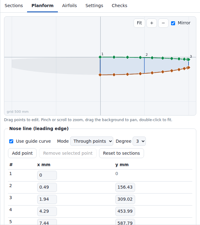
Planform tab, Glider preset. Controls: User Guide, section Planform.
| Enabled guide curves | x_LE | Chord c |
|---|---|---|
| none | blended x | blended chord |
| nose line | nose line x | blended chord |
| end line | end line x − c | blended chord |
| both | nose line x | end line x − nose line x |
z and twist are always blended.
| Wing tip | Geometry |
|---|---|
| Flat (cut at the tip section) | the wing ends at the tip section with a planar cap |
| Pointed (tip profile scaled down) | the tip section gets the chord c_tip (default 1/200 of c(y_prev), at least 1 mm); the wing ends in a planar cap with chord c_tip; with both guide curves the tip chord is the guide gap at y_tip, at least c_tip |
Pointed tip:
c_tip = max(r · c(y_prev), 1 mm)
| Item | Value |
|---|---|
| y_prev | span position of the second-last section |
| c(y_prev) | chord there, after guide curves |
| r | 1 / q. q: value of Tip profile scale 1 : N of the previous section chord. Range 100 to 1000, step 50, default 200 (r = 0.005). |
| c_tip = 1 mm (r · c(y_prev) < 1 mm) | the Sections table shows (min.) after the tip chord; not shown when the warning below applies |
| Last panel | a chord below c_tip and above −0.01 mm is raised to c_tip |
| Warning | both guide curves enabled and the tip chord (end line x − nose line x at y_tip) larger than c_tip + 0.5 mm; the wing then ends with that chord; the message gives both chords |
Example: Glider preset (guide curves end 90 mm apart) with Wing tip = Pointed: c_tip = 1 mm, tip chord 90 mm, warning "nose line and end line end 90.0 mm apart, so the tip chord is 90.0 mm instead of 1.00 mm".
Check positions y:
- every station of section 3.2
- 257 evenly spaced positions: y_root + (y_tip − y_root) k / 256, k = 0 … 256
- y of every guide control point and of the guide curve point at every knot, mapped linearly onto [y_root, y_tip]
Thickness at a check position, as a fraction of the chord (upper minus lower point at the same chord station):
t_k = z_unit,(N−k) − z_unit,(N+k) k = 1 … N − 1
Chord stations beyond 99 % of the chord (s_k > 0.99): a negative t_k up to min(1e-4, 0.1 mm / c) in magnitude counts as 0. The resampled TE of a cusped airfoil can lie in a crossing loop that the curve check of section 1.4 accepts (loops with a mean width up to 5e-4 of the chord, at most 0.1 mm).
Fitted positions: the check positions plus the quarter points 0.25, 0.5 and 0.75 of every station interval after the final fit (section 3.2).
Local thickness of the fitted surface at y, for the compared chord stations k of section 3.2: the surface points S(u_(N−k), v) and S(u_(N+k), v) transformed back into the unit-chord frame of the station at y (translation, roll, chord scale, twist and stretch undone), upper z minus lower z.
Checks in code order. Every row is an error; no surface is built.
| Check | Condition |
|---|---|
| Section count | fewer than 2 sections |
| Project limits | a section chord above 100,000 mm, a section x, y or z outside ±1,000,000 mm, a twist outside ±360°, more than 20,000 sections, or a guide curve (on or off) with more than 20,000 points, a point x outside ±1,100,000 mm or a point y outside ±1,000,000 mm. Same limits as on Open (limitErrors in src/model/project.js), so a project that cannot be saved cannot be exported. Every exceeded limit gives one message, e.g. "Section 3: twist must be within ±360 degrees." or "Section 2: chord must be at most 100000 mm." More than 20,000 sections: only the message "At most 20,000 sections are supported (found N).", the sections are not read. A guide curve above 20,000 points: "guides.nose.points: at most 20,000 points (found N)." (end line: guides.end.points). |
| Root side | first section (after sorting by y) at y < 0: "lies on the mirrored side" |
| Section positions | 2 sections with the same y |
| Airfoil reference | a section uses an airfoil id missing in the project |
| Airfoil | sanity-check error, failed NURBS interpolation, self-crossing NURBS curve (section 1.4) or x reversal (section 1.5). With Chord length or Uniform parametrization the message ends with 'Settings > Profile parametrization "centripetal" follows the points more closely.' |
| Guide curves | a condition of section 3.3 violated |
| Straight panels | Straight panels with a guide curve on (section 3.1) |
| Section planes, stretch |
Mitred section planes: a section whose plane lies more than 60° from a panel next to it (its panel angle, section 3.8), a stretch m above 2 (MAX_STRETCH in src/geom/planes.js): a first panel steeper than 60°, or a dihedral change of more than 120° at a section. A plane that rounds to 60.0° counts as within the limit (below 60.05°, STRETCH_LIMIT): section positions hold 4 decimals. The stretch is never clamped. Message, with the angle to 1 decimal and the stretch to 3: "Section n: its mitred plane lies …° from the panel next to it, which stretches the airfoil … times (limit 2, 60°). Reduce the dihedral change there or set Settings > Section planes to Vertical." Example: a first panel at 65°: "… lies 65.0° … stretches the airfoil 2.366 times …". |
| Loft grid | more than 5,000,000 grid points with the stations per panel used (section 3.2) |
| Section planes, fold |
Mitred section planes, Straight panels: the planes of two neighbouring sections of different roll meet in a line parallel to x. The surface between them folds when that line passes through either placed airfoil (its extent along the up direction of its plane, with chord, twist and stretch), when the two airfoils lie on opposite sides of the line, or when the inner airfoil lies outboard of the plane of the outer one (planeFold in src/geom/planes.js). Message: "Sections a and b: their mitred planes meet … mm from the position (y, z) of section a, within the airfoils, so the surface between them folds. Lengthen the panel, reduce the dihedral change or set Settings > Section planes to Vertical." Example: panels of 0°, 40° (10 mm long) and 80°, NACA 0012 at 300 mm chord: the planes rolled 20° and 60° meet 14.6 mm from section 2, inside its ±19.2 mm; at 150 mm chord (±9.6 mm) the surface builds. Linear panels: the check "Section planes, turning". |
| Section values | x_LE, c, z or cos(twist) of a check position is not a finite number. Message: "Section values give non-finite coordinates at y = … mm; check the positions, chords and twists of the sections." |
| Geometry extent | at a check position: x_LE, x_LE + c (trailing edge) or z beyond ±1,200,000 mm (LIMITS.maxExtent), or c above 100,000 mm. The blends stay within the section values (section 3.1), so the causes are guide curves: a guide curve close to ±1,200,000 mm, where the chord added to it or taken from it leaves the extent; nose line and end line more than 100,000 mm apart. Message: "At y = … mm the wing leaves the project limits (leading-edge x … mm, z … mm, chord … mm; limits ±1200000 mm and 100000 mm chord). Check the guide curves." |
| Section planes, smooth stretch | Mitred section planes, Smooth, at every check position: the stretch m = 1 / cos(φ − δ) of section 3.8, with φ of the cubic and δ as in section 3.8 (stored panel angles included), above 2 (a plane that rounds to 60.0° builds) or not above 0 (a plane more than 90° off). Message, with the angle |
| Section planes, turning | Mitred section planes, Linear or Smooth: at a check position in a panel whose two planes differ, the roll φ changes along y by dφ/dy = (φ_(i+1) − φ_i) / (y_(i+1) − y_i) with Linear, by the derivative of the cubic with Smooth. A point at height t in the plane of its station (along the up direction, with chord, twist and stretch) moves across that plane at the rate cos φ + tan δ · sin φ − t · dφ/dy per mm of span; t is the highest point of the airfoil where dφ/dy > 0, the lowest where dφ/dy < 0; δ is the dihedral from the section positions, the direction in which the station moves, also where the panel stores a panel angle; with Smooth the dihedral of the blended reference line at the position. At the position of a section both panels next to it are tested (Linear). At 0 or below the surface folds, also where the planes of the stations around the position do not cross. Message: "Sections a and b: at y = … mm the mitred section planes between them turn faster than the airfoils allow, so the surface folds. Lengthen the panel, reduce the dihedral change or set Settings > Section planes to Vertical." Example: NACA 0018 at 217 mm chord, rolls 0° and 46.9° over a 21.7 mm panel: at the root 1 − 30.4 mm · 0.0377/mm < 0; the end planes meet 46 mm up the root plane, beyond the airfoil. Straight panels are ruled between the sections; the check "Section planes, fold" covers them. |
| Blended thickness | min t_k < −1e-9 at a check position. Both blends keep t_k between the values of the two sections of the panel (section 3.1), so the cause is a section airfoil whose upper and lower surface cross at that chord station; remedy in the message: check the airfoils or raise Chordwise stations per surface. The message gives y and x. |
| Thickness after the Trailing edge setting | min t_k < −1e-9 after the gap change of section 3.7. Checked at positions with c ≥ 1 mm. Fixed thickness in mm: gap limited to 5 % of the chord. Cause: the airfoil is thinner inside than the set TE gap. |
| Surface contact | min t_k ≤ 1e-5 (0.001 % of the chord) at chord stations s_k from 0.01 to 0.99, after the gap change of section 3.7. Checked at positions with c ≥ 1 mm. The message gives y and x. As in the airfoil files: remedy Linear or more sections; other modes: remedy As in the airfoil files or a thicker TE. |
| Chord | minimum chord < 1 mm; the message gives the chord and its y. The blends keep the chord between the section chords of at least 1 mm, so only nose line and end line together set a smaller chord (their distance). |
| Chord, hint | as above, minimum at the tip, chord > −0.01 mm, Wing tip = Flat: the message adds "set Settings > Wing tip to Pointed" |
| Station planes | Mitred section planes, after the fit: for two neighbouring stations of different roll, a point of the outer station does not lie beyond the planes of both stations, seen from the same point of the inner station. Message: "The surface folds between the stations at y = … mm and y = … mm (panel from section a to b): their section planes cross within the airfoils. Lengthen the panel, reduce the dihedral change or set Settings > Section planes to Vertical." |
| Fitted surface, finite | after the surface fit and the added stations (section 4): a control point coordinate is not a finite number. Message: "The fitted surface has non-finite coordinates; check the positions, chords and twists of the sections." |
| Fitted thickness | at every fitted position: local thickness of the fitted surface < −1e-9 (beyond 99 % chord: < −min(1e-4, 0.1 mm / c)) at a compared chord station ("The fitted surface turns inside out between stations"), or ≤ 1e-5 (0.001 % of the chord) at a compared chord station from 1 % to 99 % chord ("The fitted surface has zero thickness between stations"). The message gives y and the thickness. Cause in the message: the surface through the stations swings between them (guide curves that change fast). Remedy in the message: smooth the guide curves or add sections. |
| Fitted chord | at every fitted position: c_fit < 0.9 mm (1 mm minimum chord less 10 %). c_fit = ((S(0, v) + S(1, v)) / 2 − S(u_LE, v)) projected onto the intended chord direction of the station at y, in 3D. Message: "The fitted surface folds or narrows between stations" |
| Surface self-crossing | the surface row at a section, halfway between 2 neighbouring sections or halfway between the 2 stations of one of the 64 widest station intervals (added stations included) crosses itself in the plane of its station (section 1.4) with a loop size (mean width) above 5e-4 · c; 4 samples per knot span (section 1.4) |
Per station, after blending:
| Trailing edge | Gap g as a fraction of the chord |
|---|---|
As in the airfoil files (asis) |
blended shape unchanged |
Closed (sharp) (closed) |
g = 0; both end points move to their midpoint |
Fixed thickness in mm (thickness) |
g = t / c, t = Trailing-edge thickness (mm) (default 0.4 mm), limited to 5 % of the chord |
| Project | Trailing edge | t |
|---|---|---|
| Default of the project model (project files without this setting) | As in the airfoil files | 0.4 mm (unused) |
| Sample wing "Sport wing 1500" (first visit) | Fixed thickness in mm | 0.5 mm |
| Projects from the wizard | Fixed thickness in mm | max(0.3 mm, 0.2 % of the root chord), rounded to 0.01 mm; Glider 0.4 mm, Sport 0.48 mm, Tail surface 0.3 mm |
Gap change: the upper surface moves up and the lower surface down by half the change. The weight rises linearly from 0 at the leading edge to 1 at the TE, so the leading edge stays in place.
δ = (g − g_current) / 2
w = clamp((x − x_LE) / (x_TE,branch − x_LE), 0, 1)
upper surface:  z ← z + δ w
lower surface:  z ← z − δ w
Negative thickness after this change is a build error (section 3.6).
TE topology over all stations:
| Stations | TE of the surface |
|---|---|
| |gap| < 1e-6 mm at every station | closed: both end points merged at every station |
| otherwise | open: each station with a gap below min(0.01 mm, 5 % of c) is opened to that value |
| Warning | Condition |
|---|---|
| thickness limited | t / c > 5 % at 1 or more stations; stations in the last panel of a pointed tip are not counted |
| stations opened | open TE and 1 or more stations with a gap below the minimum |
Unit-chord point (x_unit, z_unit) from section 2, twist θ, pivot f_pivot, roll φ and stretch m of the section plane. The twist turns the airfoil in its plane about the pivot (f_pivot, 0); the stretch scales its thickness before the twist.
dx  = x_unit − f_pivot
r_x =  dx cos θ + m z_unit sin θ
r_z = −dx sin θ + m z_unit cos θ
X = x_LE + c (f_pivot + r_x)
Y = y − c r_z sin φ
Z = z + c r_z cos φ
The section plane passes through the section position (y, z), which the untwisted leading edge, the pivot and the trailing edge share. Its up direction is (0, −sin φ, cos φ), its normal (0, cos φ, sin φ). With φ = 0 and m = 1 the section lies in the plane Y = y.
Settings > Section planes (settings.sectionPlanes, src/geom/planes.js):
| Value | Roll φ | Stretch m |
|---|---|---|
Mitred (square to the panels, as XFLR5) (mitred, default of new projects) |
root 0; a section between panels i − 1 and i: (δ_(i−1) + δ_i) / 2, the bisector plane; tip: δ of the last panel, square to it. δ: the panel angle (below) | 1 / cos(φ − δ) with δ of the panel outboard of the section (the tip: the last panel; at a bisector both panels give the same value): root 1 / cos δ_0, a break 1 / cos((δ_i − δ_(i−1)) / 2), tip 1 |
Vertical (y = const) (vertical) |
0 | 1 |
- Stations between sections: φ is blended like the twist (section 3.1). Linear: m = 1 / cos(φ − δ) with δ of the panel of the station. Smooth: φ follows the shape-preserving cubic through the rolls of the sections, and δ is the dihedral of the blended reference line at the station, atan(dz/dy) of the cubic through the section positions z; m = 1 / cos(φ − δ). At a section δ is the slope of the cubic there, not the dihedral of a panel, so the stretch at the sections differs from Linear. Stored panel angles add their difference from the dihedral of their panel to δ, blended along the span like the rolls (at a section the mean of the two panels next to it, at root and tip the value of its one panel; a panel narrower than 1 mm in y adds nothing), so δ stays continuous. A panel narrower than 1 mm in y takes the angle its two sections share (short panels, below), as with Linear. The check "Section planes, turning" takes δ from the section positions alone.
- Thickness across a panel, or across the blended reference line with Smooth: m cos(φ − δ) = 1 of the airfoil thickness with Mitred, cos δ with Vertical. 35° V-tail: the vertical sections are 81.9 % as thick across the panel; the mitred root holds the airfoil stretched 1.221 times.
- The twist turns the airfoil about the normal of its plane, as in XFLR5 and flow5. Seen along x, a section rolled φ with twist θ meets the flow at atan(tan θ cos φ): 1.64° for 2° twist at 35°.
- The root plane is vertical in both modes, so the two halves meet in the plane y = 0.
- Smooth moves a wing with dihedral against Linear where the cubic bends the reference line; the presets of the wizard with Smooth move by up to 1.8 mm against vertical planes (Sailplane, 10° outer dihedral). At the root the plane stays vertical while the cubic can leave it up to 3 times as steep as the first panel (section 3.1); the check "Section planes, smooth stretch" (section 3.6) stops a stretch above 2 there.
- Panel angle: a section can store the angle of the panel to the next section (Sections column
Panel angle, shown with Mitred;
panelAnglein the project file, degrees, within ±89.9999°). The planes use it as δ of that panel, for the rolls and for the stretch. Empty: δ from the section positions; the field shows it as "auto …". The tip section has no panel. The XFLR5 import stores XFLR5's dihedrals (below). - The planes follow the section positions. A section moved in z changes the rolls of its planes and of its neighbours' planes. A stored panel angle stays when a section moves. A section inserted halfway along a panel takes over the panel angle that the panel stores.
- Short panels: a panel less than 1 mm wide in y (
SHORT_PANELinsrc/geom/planes.js) counts as no panel. The sections at its ends share one plane: the bisector plane of the panels around it; before the first panel the vertical plane, after the last panel the plane square to it. Their stretch refers to those panels. XFLR5 skips panels shorter than 0.1 mm along the span in the same way. Current limitation: a panel 0.1 mm to 1 mm long in an XFLR5 file is a panel in XFLR5 and none in Wingdesigner; its two sections lie in one plane. - Limits: stretch at most 2 and no fold between neighbouring planes (section 3.6).
- Project files of format version 1 hold no section-plane setting and open with Vertical (File Formats).
Sections written by an XFLR5 import. XFLR5 is a program for the analysis of airfoils and wings. The import sets Twist pivot (fraction of chord) (f_pivot) to 0.25, the point about which XFLR5 twists a section, Spanwise interpolation to Straight panels, the construction of XFLR5's panels (section 3.1), and Section planes to Mitred, XFLR5's planes. A part whose mitred planes would fold imports with Vertical section planes. The tilt angle of the wing in the XFLR5 plane becomes Part tilt about the wing origin (section 3.9). It also applies a frame rule. XFLR5 draws the coordinates of an airfoil as they are; the build puts the leading edge of the airfoil curve (section 1.3) at the section origin and scales the airfoil to chord 1 (section 2). Where the coordinates that XFLR5 used are known (an airfoil of the .xfl file, an uploaded .dat file, a NACA section), the import moves and scales the section by the difference, so that the airfoil lies where XFLR5 draws it. Every difference applies; the report names those above 0.1 % of the chord. The move turns a panel whose two sections move differently (two airfoils, or one airfoil at two twists). Such a section stores XFLR5's dihedral as its panel angle when it differs by more than 0.001° from the dihedral of the moved sections, so the planes and stretches stay XFLR5's. Sections with a library airfoil or another airfoil of the current project keep the values of the file. How the import sets the sections, the pivot and the interpolation, with the rules and formulas: File Formats, section XFLR5 import, subsection Mapping to sections.
Settings > Part tilt (°, positive = leading edge up) (t, settings.partTilt) and Part roll
(°, positive = right tip up) (r, settings.partRoll) turn the whole half wing as a rigid body
(src/geom/part.js). Both lie within ±180°, default 0°. Sections 3.1 to 3.8, the surface of section 4
and the build checks work in the frame of the part; the transform T applies to the fitted surface.
Pivot P = (P_x, P_y, P_z): settings.partPivot when stored (the XFLR5 and flow5 imports store the
wing origin with P_y = 0), else the leading edge (x, y, z) of the root section. Settings names it below the
two fields.
first the roll r about the x axis through P:
  x1 = x − P_x
  y1 = (y − P_y) cos r − (z − P_z) sin r
  z1 = (y − P_y) sin r + (z − P_z) cos r
then the tilt t about the y axis through P:
  X = x1 cos t + z1 sin t + P_x
  Y = y1 + P_y
  Z = −x1 sin t + z1 cos t + P_z

T(p) = M (p − P) + P      M = | cos t    sin t sin r    sin t cos r |
                              | 0        cos r          −sin r      |
                              | −sin t   cos t sin r    cos t cos r |
- Signs: a positive tilt raises the leading edge (a point ahead of the pivot, x < P_x, moves up); a positive roll raises the right tip (a point outboard of the pivot, y > P_y, moves up).
- Directions (plane normals, the reference direction x of a cap) turn by M alone.
- Left half, by Left half (
settings.leftHalf), with S(x, y, z) = (x, −y, z):-
"mirror"(default): S(T(p)), the mirror image of the turned right half at the plane y = 0. -
"turned": T(S(p)), the mirror image of the unturned right half, turned with it: the whole wing turns as one body, as flow5 turns a two-sided wing by its rollRx_angle. The left half then rolls the other way than with"mirror"; the flow5 import sets"turned"for a rolled two-sided wing (File Formats, section flow5 import). - The two agree when r = 0: a turn about the y axis keeps the plane y = 0.
- A rolled root does not lie in the plane y = 0, so the meshes do not merge the halves (section 5).
- Span (statistics): 2 |y| of the turned right tip with
"mirror"; the y distance of the turned tips with"turned".
-
- The flow5 import stores
Ry_angleas t andRx_angleas r: flow5 turns a wing first about x, then about y, both about the wing origin, with the same signs. - Extent: after the fit, every control point turned by T (with Left half
"turned"also every control point of the left half, T(S(p))) must lie within ±1,200,000 mm in x, y and z (LIMITS.maxExtent); the surface lies in the convex hull of its control points. Otherwise the build stops with:The tilted or rolled part reaches x = … mm, y = … mm, z = … mm, beyond ±1200000 mm; reduce the part tilt or roll, or move the part towards its pivot. - Turned: the 3D view (
partMatrixinsrc/ui/viewer3d.js), the STL and 3MF meshes (section 5), the STEP solids (section 6) and the positions of the statistics (section 7). In the frame of the part: the Sections table, the Planform tab, the project file and the foam cores (section 8). - A tilt about y keeps planes y = const. With Vertical section planes a tilt folded into the section values (each twist pivot point turned about P, t added to every twist) builds the same part as the rigid tilt: within 1e-6 mm in the unit tests of the upgrade of version 2 files (File Formats, section Project JSON). With Mitred planes only the rigid tilt turns the planes with the part, as XFLR5 does.
Tensor-product B-spline surface S(u, v) through the station grid Q (2N + 1 points per station).
| Direction | Parameters | Degree | Knot vector |
|---|---|---|---|
| u (around the profile) | mean of the per-station parametrizations; u_0 = 0, u_2N = 1 | 3 | clamped, by averaging; with a closed trailing edge by averaging for given end derivatives (The NURBS Book, eq. 9.22) |
| v (span) | v = (y − y_root) / (y_tip − y_root) | 1 when no panel has intermediate stations; otherwise the fewest station intervals of a panel with intermediate stations, at most 3 (min(3, K); 2 or 1 when the loft grid limit lowers K, section 3.2) | one interpolation per panel; a panel of 2 stations is the straight segment between them, raised to that degree; panels joined at the sections with interior knot multiplicity p (C0: position-continuous, kinks at sections) |
With Smooth the station values have a continuous slope at the sections (section 3.1); every panel is still interpolated on its own, so the surface is C0 there. One interpolation over all stations swings beside a short panel with a fast change: NACA 2415 to NACA 2408 between sections 0.5 mm apart next to a 300 mm panel turns that surface inside out (local thickness −34.5 % of the chord at y = 304.9 mm, Spanwise stations per panel 8).
Procedure:
- Interpolate each station row along u (one band LU factorization serves all rows). With a closed
trailing edge (
closedTE) the row also has its end derivatives given: the secants D_0 = (Q_1 − Q_0) / u_1 and D_2N = (Q_2N − Q_(2N−1)) / (1 − u_(2N−1)) to the first chord station (secantEndInterpolationinsrc/geom/nurbs.js; The NURBS Book, section 9.2.2, eq. 9.21). - Interpolate each column of the resulting control points along v (band LU, section 1.2).
- Set y of the control points at v = 0 to y_root, and project the control points at v = 1 onto the tip plane (y = y_tip for φ = 0). This removes solver round-off: the root and tip rows lie in their planes (15 STEP cases: within 3e-13 mm, section 6).
End tangents at a closed trailing edge: without given end derivatives each end takes its tangent from
the curvature of the row further in. At a cusp (thickness and wedge angle 0 at the trailing edge) the
first chord station, 6.85e-4 of the chord from the trailing edge at N = 60, is only 9e-6 to 5e-5 of
the chord thick, and the end tangent of the upper side can then lie below that of the lower side. Example,
cusped-closed (section 6), root chord 240 mm: the first chord station lies 0.164 mm from the trailing
edge and is 0.0022 mm thick, the secant slopes to it are 0.7063 (upper) and 0.6928 (lower). Free ends
give end slopes of 0.6962 and 0.7088: the upper surface lies below the lower one up to 0.046 mm from
the trailing edge (1.2e-4 mm deep), and the outline of the root cap crosses itself. Secant end
tangents give 0.7063 and 0.6928 and no crossing. A trailing edge with a gap keeps free ends.
Properties:
- S passes through every station point: S(u_j, v_k) = Q_(j,k).
- The iso-curve u = u_LE passes through the leading edge of every station.
- Control points per half: (2N + 1) × stations; (2N + 3) × stations with a closed trailing edge.
- The surface rows at each section, halfway between neighbouring sections and halfway between the stations of the 64 widest station intervals are tested for self-crossing (section 1.4).

Swept flying wing preset (3 sections, 2 added stations, Linear, no guide curve) with Settings > Show NURBS control net. The 121 net lines along the span lie so close together at this scale that they appear as shading.
| Wizard preset (N = 60, K = 8) | Stations | Control points per half | Degree u × v |
|---|---|---|---|
| Sport (1.5° dihedral, Mitred) | 9 | 121 × 9 | 3 × 3 |
| Swept flying wing (no dihedral) | 5 (2 added, section 3.2) | 121 × 5 | 3 × 1 |
| Glider (elliptic guide curves, Tip = Flat) | 17 | 121 × 17 | 3 × 3 |
| Glider (elliptic guide curves, Tip = Pointed (1/200 scale)) | 22 (5 added, section 3.2; largest deviation 0.263 mm, no warning) | 121 × 22 | 3 × 3 |
Triangle meshes for STL (stereolithography) and 3MF (3D Manufacturing Format) export and for the 3D view.
| Direction | Samples |
|---|---|
| u | station parameters u_j; each interval divided into d parts |
| v | station parameters v_k; each interval divided into r · d parts; r = 1 (degree 1 along v), r = 3 (degree 2 or 3) |
d = Mesh density (STL, 3MF): 1 (Normal) or 2 (Fine (4x triangles)). The 3D view samples with d = 1. The counts below apply to the export meshes.
Counts per half (n_u = 2N · d, V = number of v samples):
| Item | Open TE | Closed TE |
|---|---|---|
| Vertices per v sample | n_u + 1 | n_u (TE vertex shared) |
| Surface triangles | 2 n_u (V − 1) | 2 n_u (V − 1) |
| TE strip triangles | 2 (V − 1) | 0 |
| Triangles per cap (root, tip) | n_u − 1 | n_u − 2 |
Example: Sport preset, N = 60, d = 1, open TE: Mitred section planes (9 stations, degree 3 along v, V = 25): 3,025 vertices, 6,046 triangles per half; Vertical (2 stations, degree 1, V = 2): 242 vertices, 480 triangles.
- Orientation: every triangle faces outward (normal S_v × S_u).
- Caps: the root and tip outlines are triangulated in the plane of their section (x and the up direction of its roll φ; the x-z plane for φ = 0). Upper point k pairs with lower point k (same chord station): 2 triangles per station interval, linear time.
- Other diagonal: when a triangle of a quad is not counterclockwise, the quad uses its other diagonal (refined chord stations do not pair exactly). With one diagonal only, a Fine cap with a closed trailing edge (NACA 4415, 200 chord stations per surface) falls back to ear clipping: 2.2 s.
- Cap fallback: ear clipping. It applies when a quad has a triangle that is not counterclockwise with either diagonal. It also applies when the triangle areas differ from the outline area by more than 1e-9 (relative). Both areas are summed relative to a vertex of the outline, so a wing 1,000,000 mm from the origin keeps the strips.
- Part placement (section 3.9): the vertices of the half wing are turned by T before the mirror.
- Left half: y → −y, triangle winding reversed. With Left half
"turned"and a part roll, the mirror comes first and T turns the mirrored vertices (section 3.9).
| Wing halves | Shells |
|---|---|
| Both halves as separate bodies | 2 closed shells, root caps included |
| Full wing as one body (mesh formats, root at y = 0) | root at exactly y = 0 mm and Part roll 0°: 1 closed shell, the halves share the root vertices, no root caps; otherwise 2 shells |
| Right half only | 1 closed shell |
| Left half only | 1 closed shell, the left half |
STEP file as defined in ISO 10303 (ISO: International Organization for Standardization), schema AP214 (Application Protocol 214). Each half is one
MANIFOLD_SOLID_BREP (boundary representation solid) with one CLOSED_SHELL. Solid names:
<name> right, <name> left. Header, units and tolerance: File Formats.
| Wing halves | Solids |
|---|---|
| Right half only, Left half only | 1 (<name> right or <name> left) |
| both other options | 2 (the halves are never merged in STEP) |
Part placement (section 3.9): every point (control points of surfaces and curves, vertices, the
origins of the cap planes) is turned by T, every direction (cap normals and reference directions) by
M; the left half is mirrored after the turn, or before it with Left half "turned" (section 3.9); then the Fusion 360 fix turns the axes. Placement and turn are
rotations and keep the orientation flags. The tables below give the normals in the frame of the part.
Split: the surface is split at u_LE by knot insertion (A5.1) up to multiplicity 3 on every v column. A split parameter within 1e-10 of an existing knot snaps to that knot. Both parts get knot vectors renormalized to [0, 1].
| Part | u = 0 | u = 1 |
|---|---|---|
| Upper surface | upper TE | leading edge |
| Lower surface | leading edge | lower TE |
Faces of the right half; (+) = edge used in its own direction, (−) = reversed:
| Face | Surface | Edge loop |
|---|---|---|
| Upper |
B_SPLINE_SURFACE_WITH_KNOTS, degree 3 × degree along v |
upper TE (+), tip upper (+), leading edge (−), root upper (−) |
| Lower |
B_SPLINE_SURFACE_WITH_KNOTS, degree 3 × degree along v |
leading edge (+), tip lower (+), lower TE (−), root lower (−) |
| TE (open TE only) | ruled B-spline surface, degree 1 in u (knot vector (0, 0, 1, 1)) between the lower and the upper TE control rows | lower TE (+), tip line (+), upper TE (−), root line (−) |
| Root cap |
PLANE, normal −y (the root plane is always vertical), origin at the root leading edge |
root upper (+), root lower (+), root line (+, open TE only) |
| Tip cap |
PLANE, normal (0, cos φ_tip, sin φ_tip) (+y for a vertical tip), origin at the tip leading edge |
tip lower (−), tip upper (−), tip line (−, open TE only) |
| TE | Faces | Edges | Vertices |
|---|---|---|---|
| Closed | 4 | 6 | 4 |
| Open | 5 | 9 | 6 |
- Closed TE: upper TE and lower TE are one edge with 2 shared vertices.
- Edges of a B-spline face: the exact boundary iso-curve of that surface (first or last control row or column).
- Edge curve type:
B_SPLINE_CURVE_WITH_KNOTS. Root line and tip line have degree 1.
Orientation flags:
| Flag | Right half | Left half (mirrored) |
|---|---|---|
same_sense of the B-spline faces |
.F. (S_u × S_v points inward) |
.T. |
same_sense of the plane faces |
.T. |
.T. |
FACE_OUTER_BOUND orientation |
.T. |
.F. (every loop reversed) |
| Plane normal | root −y, tip (0, cos φ_tip, sin φ_tip) | mirrored as vectors: root +y, tip (0, −cos φ_tip, sin φ_tip) (outward) |
Part placement: points and directions of the right half turn by T and M; those of the left half by S ∘ T or T ∘ S (Left half, section 3.9). The flags stay as in the table: the mirror reverses the orientation, the turn keeps it.
Validation: scripts/validate_step.py reads the files written by scripts/export-step-cases.mjs
with OpenCascade. Cases: the 15 cases of test/step-cases.js, 1 of them with a closed, cusped trailing
edge (cusped-closed, section 4), 6 of them with Mitred section
planes (a 35° V-tail with Straight panels, written once without and once with the Fusion 360
fix (Y up), a 15°/−5° gull with Linear and with Smooth, an airfoil switch with Straight panels: two
sections 0.5 mm apart in y in one plane between panels of 0° and 10°, the outer panel with a stored
panel angle of 10.5°, and part-tilt-roll: the gull with Part tilt 8° and Part roll 12°
about the pivot (50, 0, −20) mm). On part-tilt-roll both solids are valid and closed, the volume
lies within 3.2e-5 of the mesh volume and the cap edges within 1.9e-13 mm of their planes.
Fusion 360 fix of the export (File Formats, section "Bodies per file"): every point and direction of the part is written as (x, z, −y). The turn is a rotation, so the orientation flags stay.
Pass criteria per file:
- read status
IFSelect_RetDone - solid count = expected count: 2;
root-offset-half(Right half only): 1 - per solid:
BRepCheck_Analyzerreports it valid - per solid: the shell is closed (no free edges, no bad orientation)
- per solid: volume > 0
- per solid: volume within 5e-4 (relative) of the mesh volume at u × 4 and v × 8 refinement
- per solid: every edge of a planar face (the caps) lies in its plane within 1e-6 mm, sampled at 51 points per edge. A tip cap written vertical on the 15°/−5° gull lies 0.67 mm off its edges and changes the volume by only 0.0475 %, below the volume tolerance.
MAC: mean aerodynamic chord. The integrals use the intended planform: x_LE(y) and c(y) of section 3.4,
including guide curves and the chord floor of a pointed tip (planformAt in src/geom/wing.js).
Quadrature: 5-point Gauss-Legendre, exact for polynomials up to degree 9, on each interval [y_a, y_b]
between neighbouring breakpoints. Breakpoints: root, tip, the sections and, for each enabled guide
curve, every knot and control point mapped to the wing span (planformBreaks in src/geom/wing.js).
Stations are no breakpoints: the intended planform does not bend there, and splitting at 139,994
stations (20,000 sections, guides of 20,000 points) took 27 s. An interval is halved while the two
halves change one of the 4 integrals by more than 1e-10 of its scale, at most 12 times
(REL_TOLERANCE, MAX_DEPTH in src/geom/stats.js).
S_half   = ∫ c dy
MAC      = ∫ c² dy     / S_half
y_MAC    = ∫ c y dy    / S_half
x_LE,MAC = ∫ c x_LE dy / S_half
x_25     = x_LE,MAC + 0.25 · MAC
b        = 2 · y_tip           (frame of the part; turned part: below)
S        = 2 · S_half
AR       = b² / S

∫ f dy   ≈ Σ_intervals (Δy / 2) Σ_i w_i f(y_a + (1 + t_i) Δy / 2)
t_i      = 0, ±0.538469310105683, ±0.906179845938664
w_i      = 0.568888888888889, 0.478628670499366, 0.236926885056189

halve [a, b] while |I_left + I_right − I_whole| > 1e-10 · max(s, 1) · (b − a) for one integral,
                   at most 12 halvings
s        = c_max, c_max², c_max · y_max, c_max · max(|x_LE| + c)   (per integral, over the stations)
A tilted or rolled part (section 3.9) gives the positions in the plane axes: the MAC leading edge and the 25 % MAC point turn with the part, at the height z of the stations. S, MAC, the root and tip chord and the quadrature stay in the frame of the part.
z_MAC              = z at y_MAC, linear between neighbouring stations
y_MAC', x_LE,MAC'  = Y and X of T(x_LE,MAC, y_MAC, z_MAC)
x_25'              = X of T(x_LE,MAC + 0.25 · MAC, y_MAC, z_MAC)
b                  = 2 · Y of T(x_LE, y, z of the tip station)
AR                 = b² / S
- With a roll, b = 2 · |(y_tip − P_y) cos r − (z_tip − P_z) sin r + P_y|: a roll that lifts the tip shortens the span; beyond 90° the right tip lies at y < 0 and the tips stay 2 |y| apart; e.g. 30° on the sample wing of the unit tests. A tilt keeps b (Y = y without a roll).
- MAC position shows y_MAC' and x_LE,MAC', 25 % MAC (geometric reference) shows x_25'.
| Planform between 2 neighbouring breakpoints | Quadrature |
|---|---|
| Linear or Smooth, no guide curve | exact: c and x_LE have degree ≤ 3 in y, the integrands degree ≤ 6 |
| a guide curve enabled, or the chord raised to c_tip in the last panel of a pointed tip | not exact on every interval: x(y) of a Control points guide is not a polynomial, the chord floor is a kink; the halving refines these intervals |
Quadrature error against the midpoint rule with 200,000 intervals (differences of this size lie within the error of the midpoint rule itself):
| Case | S | MAC | y_MAC | x_LE,MAC |
|---|---|---|---|---|
| Glider, Tip = Flat | −2.2e-10 % | −6.7e-12 % | −4.2e-10 % | 3.2e-12 mm |
| Glider, Tip = Pointed (1/200 scale) | −2.1e-9 % | 2.0e-9 % | −3.1e-9 % | −8.6e-10 mm |
| other planforms with guide curves | not measured | not measured | not measured | not measured |
- b: span, S: wing area, AR: aspect ratio. b, S and AR cover both halves.
- MAC, y_MAC and x_LE,MAC are computed on one half.
- With y_root > 0, b includes the centre gap 2 · y_root and S does not.
- Show mirrored half (y < 0) changes only the display; the values stay the same.
- x_25 is a geometric reference, not a neutral point or centre-of-gravity calculation.
- A build result without
planformAtfalls back to the trapezoid rule over the stations;buildWingalways setsplanformAt.
| Checks row | Value | Unit, decimals |
|---|---|---|
| Span | b | mm, 1 |
| Wing area | S | dm², 2 |
| Aspect ratio | AR | –, 2 |
| Mean aerodynamic chord (MAC) | MAC | mm, 1 |
| MAC position | y_MAC, x_LE,MAC | mm, 1 |
| 25 % MAC (geometric reference) | x_25 | mm, 1 |
| Root / tip chord | c of the first and of the last station | mm, 1 |
| Surface | degree u × degree v; control points (2N + 1) × stations, (2N + 3) × stations with a closed trailing edge | – |
| Trailing edge |
closed or open (section 3.7) |
– |
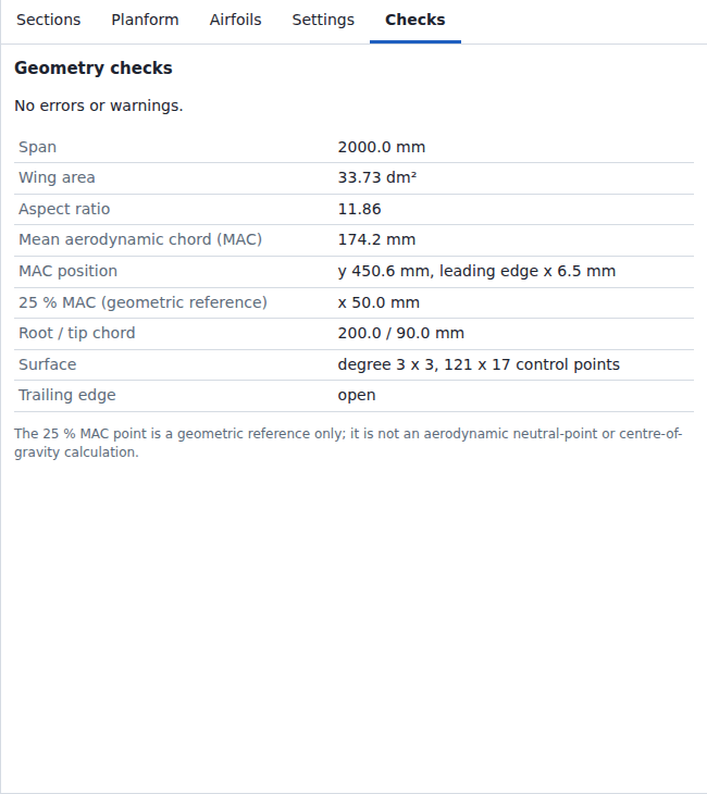
Example: Glider preset (Tip = Flat, N = 60, K = 8): Span 2000.0 mm, Wing area
33.73 dm², Aspect ratio 11.86, MAC 174.2 mm, MAC position y 450.6 mm, x 6.5 mm, 25 % MAC
x 50.0 mm, Root / tip chord 200.0 / 90.0 mm, Surface degree 3 × 3, 121 × 17 control points,
Trailing edge open.
The foam-cutting wizard (User Guide, section Foam cutting) splits the half wing into
segments. Each segment is one foam core. A hot wire cuts it as a ruled surface: straight lines
between two end profiles. Code: src/geom/foam.js. The cores lie in the frame of the part: Part
tilt and Part roll (section 3.9) do not change them.
A cut is a span position y in mm. Root and tip are the ends; the cuts lie between them.
| Rule | Value |
|---|---|
| Proposal | A cut at every section between root and tip. Each piece between them splits into n = min(ceil(L / L_max), floor(Δy / 5 mm)) parts of equal length along the reference line; a curved line (Smooth blending) gets shorter parts in y where it is steeper. L: length of the reference line of the piece; Δy: its extent in y; L_max: Longest core. The second bound keeps the parts at least 5 mm apart in y on a straight panel; on a curved line a cut closer than 5 mm in y to the one before is dropped. Within 200 segments the section cuts stay; when the pieces ask for more cuts than are left, each gets its share in proportion to the cuts it asks for (largest remainders first, then inboard) |
| Reference line | (y, z) of the stations, linear between them. Its length counts the dihedral: 600 mm in y at 1.5° are 600.2 mm |
| Shortest segment | 5 mm in y. A cut closer than 5 mm to the cut before it, to the root or to the tip is dropped |
| Sections closer than 5 mm | One cut, at the first of them |
| Segments | at most 200 per half wing; further cuts are dropped |
z_ref(y)  = z of the stations, linear in y between them
α         = atan2(z_ref(y_b) − z_ref(y_a), y_b − y_a)       axis angle of the segment (°)
a         = (0, cos α, sin α)                               axis direction
up        = (0, −sin α, cos α)                              up direction of the end faces
y_a and y_b are the inboard and the outboard cut. Without dihedral α = 0, a = (0, 1, 0) and up = (0, 0, 1).
The joint plane at a cut is where two cores meet, or where a core ends at root or tip:
| Cut | Joint plane |
|---|---|
| Root, tip, a section | the section plane of the station there (section 3.8): vertical, or rolled by φ about x |
| Between two sections | the bisector of the two segment axes: square to both when α is equal on both sides |
n         = (0, cos φ, sin φ)                    normal of a section plane
n         = (a_k + a_(k+1)) / |a_k + a_(k+1)|    bisector of segments k and k + 1
q(u)      = point of the wing surface in the joint plane, for each u of the surface
d_in      = min over u of q_in(u) · a             inboard end face  {p : p · a = d_in}
d_out     = max over u of q_out(u) · a            outboard end face {p : p · a = d_out}
L_core    = d_out − d_in                          core length along the axis
- The end faces are square to the axis and parallel: the faces of a block that a hot-wire cutter makes.
- Each end face lies where the shortest core that covers the joint profile q ends. The core is then at least as long as the wing segment, and sanding brings its end face to the joint plane.
- Points of the wing beyond the end of the segment come from the segment surface continued straight along its end tangent in v. A core does not take the shape of its neighbour across a dihedral break.
Wedge between end face and joint plane:
angle     = acos |n · a|                                     (°); none below 0.001°
depth     = max over u of q(u) · a − min over u of q(u) · a   (mm, along the axis)
side      = upper or lower: where q lies farthest from the end face
| Wing | Joint | Wedge |
|---|---|---|
| Straight panel at 10° dihedral, Mitred section planes | root (vertical plane) | 10°, h · tan 10° deep at the upper surface (h: height of the airfoil at its chord, square to the panel: 24.31 mm at 200 mm chord of NACA 2412 gives 4.29 mm) |
| same | tip (square to the panel) | none |
| same, cut halfway | bisector of equal axes | none |
| Gull: panels at 15° and −5°, Mitred | the section at the break (bisector plane) | 10° at the lower surface on both cores |
| Sample wing (Vertical planes, panels at 1.91° and 3.81°) | the section at y = 300 mm (vertical) | 1.91° at the lower surface (inboard core), 3.81° at the upper surface (outboard core) |
P(u)      = point of the segment surface in the end face {p : p · a = d}, for each u of the surface
x         = P_x − x_0
h         = P · up − h_0
(x_0, h_0) = smallest x and smallest P · up over both end profiles of the segment
- u runs over the surface parameters of the build (2N + 1 values, 121 at N = 60): upper TE, LE, lower TE.
- Point i of the inboard profile and point i of the outboard profile lie on one ruling of the core. A cutting program that moves both wire ends from point to point with the same index cuts the ruled core.
- The origin (x, h) = (0, 0) is the front lower corner of the smallest block that holds both profiles.
- Per end profile: LE = point at u_LE; TE = midpoint of the first and the last point; chord = |TE − LE|; incidence = atan2(h_LE − h_TE, x_TE − x_LE), positive nose up.
- Root find per u: the column curve C_u(v) = Σ N_i(u) P_ij is a B-spline curve in v; regula falsi with bisection steps (
solveMonotonic) to 1e-10 mm in p · a. Outside [v_a, v_b] the continued straight line gives the point in one step.
A straight panel of one airfoil at 10° dihedral:
| Section planes | End profile thickness |
|---|---|
| Mitred | the airfoil at its chord: the root is stretched by 1/cos 10° and the tip is square to the panel, so every cut square to the panel is the airfoil |
| Vertical | cos 10° = 0.985 of the airfoil: the wing is cos δ as thick across the panel (section 3.8) |
The ruled core is compared with the wing in planes parallel to the end faces: 7 planes at s = 1/8 … 7/8 of the core length, and one plane through each loft station inside the segment, where a guide curve or Smooth blending can bend the wing between the 7 planes. Each station lies in one segment, so the loft grid limit (5,000,000 points) also bounds the planes. The nearest edge of W_s to R_s(u) is searched from the same index u outward, in a window that doubles while the nearest edge lies at its border.
d_s       = d_in + s · (d_out − d_in)
R_s(u)    = (1 − s) · A(u) + s · B(u)       ruled core: A, B inboard and outboard end profile
W_s       = closed polygon of the segment surface in the plane p · a = d_s, at every u
deviation = max over s and u of the distance from R_s(u) to W_s     (mm)
| Wing | Deviation |
|---|---|
| Straight panels (Straight panels, or Linear with stations at the sections only) | 0 up to round-off (below 1e-9 mm in the tested wings) |
| Sport preset: chord 240 to 144 mm, MH 32, twist 0 to −1°, Linear, Mitred: 1 core, y = 0 to 600 mm | 0.314 mm |
| same, 2 cores, y = 0 to 300 and 300 to 600 mm | 0.079 mm |
| Glider preset (elliptic, guide curves): 2 cores, y = 0 to 500 and 500 to 1000 mm | 1.210 and 2.212 mm |
| same, split to 0.2 mm | 10 cores, at most 0.145 mm |
- A Linear panel between Mitred section planes of different roll (with dihedral, at least the root panel) gets stations between its sections (section 3.2). Its loft then follows c(y) · airfoil(y), turned by the twist θ(y): each factor is linear in y, their product is not. The ruled core misses it where the chord changes together with the airfoil or the twist: 0.314 mm on the Sport preset (MH 32 at both ends, twist 0 to −1°); up to 0.25 mm on the Sport planform without twist with NACA 2412 at the root and NACA 2410 at the tip; the Sport preset without twist deviates 0 mm. With a loft of stations at the sections only, taper and twist give no deviation: the Sport wing with Vertical planes deviates 0 mm.
- The deviation falls with the square of the segment length: halving a core gives about 1/4.
- Splitting (Split segments over the limit): every segment of 10 mm or more above the limit is cut in the middle (in y), and the whole set is computed again; this repeats until no such segment is left or 200 segments are reached. A segment shorter than 10 mm is not split.
- Time in Node.js 24 on a 2.1 GHz server processor: 5 to 19 ms for the proposal of the 6 wizard presets with a straight or elliptic planform, about 1 s for 200 segments of the Glider.
src/model/winglet.js appends the winglet as sections; the loft treats them as any other panel. Input: the tip section T (y_T, z_T, x_T, chord c_T, twist t_T), the angle a0 of the last panel (its stored Panel angle, else atan2(z_T − z_P, y_T − y_P) with P the section before T), and the parameters height H, cant a1, radius R, sweep Λ, tip chord share k, toe τ.
turn  = a1 − a0                          (degrees)
n     = ceil(|turn| / 15°)               arc steps; 0 when R = 0
L_arc = R · |turn| · π/180               must be shorter than H
σ     = sign(turn)

arc section j = 1 … n:   b_j = a0 + turn · j / n,   s_j = L_arc · j / n
  y_j = y_T + σ · R · (sin b_j − sin a0)
  z_j = z_T + σ · R · (cos a0 − cos b_j)

winglet tip:             s = H
  y = y_n + (H − L_arc) · cos a1,   z = z_n + (H − L_arc) · sin a1      (y_0 = y_T, z_0 = z_T)

at length s:   x = x_T + s · tan Λ,   chord = c_T + (k · c_T − c_T) · s / H,   twist = t_T + τ · s / H
- The arc is tangent to the last panel at T. With R = 0 the reference line kinks at T.
- Values are rounded to 0.01 mm and 0.01°. An arc section less than 1 mm (
SHORT_PANEL) in y from the section before it or from the winglet tip is left out. - The cant angle stays within ±89°: y is the span parameter of the loft, so every panel has to advance in y. A panel narrower than 1 mm in y is refused.
- The section planes are the Mitred bisector planes of section 3.8, square to the reference line. With Vertical planes (y = const) a panel at cant angle a would be cos a as thick across the panel, 0.26 times at 75°; the dialog requires Mitred.
- Guide curves hold x and the chord as functions of y between root and tip; they would stretch over the winglet, so the dialog requires them off. A pointed tip (section 3.5) would scale the winglet tip profile; the dialog requires a flat tip.
- Default radius 0.3 c_T: on a tighter radius an airfoil about 25 % thick folds the surface on the inner side of the arc. Tested: the Sport wing with cant −89°, −45°, 0°, 45°, 75°, 89° and radius 0, 0.3 and 0.6 c_T builds without errors with Linear; with Smooth all but 2: at ±89° with 0.3 c_T the cubic bends the reference line where the arc meets the straight part, and the check "Section planes, turning" (section 3.6) stops the build. Every other preset with a flat tip and the guide curves off builds a closed wing with the default winglet, Linear and Smooth. Batwing ends in a point (chord below 1 mm with a flat tip) and is refused.