Raspberry Pi Test and Program - softerhardware/Hermes-Lite2 GitHub Wiki
This page describes how to use a Raspberry Pi to test and program a new Hermes-Lite 2.0 unit. This is part of the procedure used by the group buy manufacturer.
Install Raspberry Pi Image
-
Download and unzip the custom Raspberry Pi 20200425 Image
-
Copy the Raspberry Pi Image to an SD card, size 4GB or larger. BalenaEtcher works well. See the Raspberry Pi Documentation for more details.
-
Boot your Raspberry Pi with this image once while connected to the internet. There is an icon on the desktop to update Hermes-Lite files. Double-click on this icon to make sure you have the latest gateware images.
Setup Raspberry Pi
- Insert the SD card with the custom Raspberry Pi Image into your Raspberry Pi 3 Model B. An older RPi image required a Raspberry Pi 3 Model B with black CPU, not silver CPU. The current RPi image does not have this limitation, and will run on a RPi 3B+.
- Connect keyboard, mouse, monitor, power supply and ethernet cable to your Raspberry Pi. Leave the other end of the ethernet cable free. It will connect directly to the Hermes-Lite 2.0. No router or switch is necessary.

Connect Raspberry Pi to Hermes-Lite 2.0
- You will be making six pin-to-pin connections between the Raspberry Pi (RPi) GPIO pins and the pins of CN1 adjacent to the Cyclone IV E FPGA (U2) on the Hermes-Lite 2.0 (HL2). Use 200mm or shorter dual female jumper wires meant for 2.54mm pin headers.
- Jumper wire sources include multi-wire jumper cables, various pin counts and lengths, 3P dual female 200mm long, and 1P dual female 150mm long.
- Follow the wiring tables below. This is assuming you are using single female jumpers. For further reference, a detailed RPi GPIO pinout diagram is available.
- First row:
| RPi GPIO Pin | HL2 CN1 Pin |
|---|---|
| 20 | 2 |
| 22 | 1 |
| 24 | 3 |
| 26 | 5 |
| 28 | 9 |
| 30 | 10 |
- Connect Ethernet and Power to HL2 as shown below. The HL2 can use a center positive 5.5mm x 2.1mm barrel connector 12V power supply supplying at least 2A.

- If you are just programming the EEPROM, skip ahead to the Program section below.
Connect Hermes-Lite 2.0 to N2ADR Filter Board
Connect the Hermes-Lite 2.0 to a N2ADR filter board using the small jumper card with 20x2 connector as seen in the picture below.
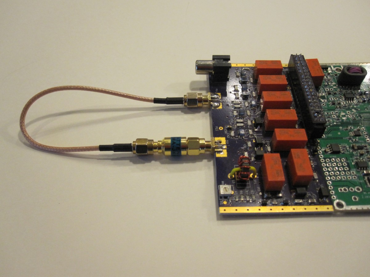
Connect the attenuator with loopback cable as seen in the picture above. The attenuator is a common 2W 50Ohm DC-6GHz 30dB inline SMA coaxial attenuator. The one I used is marked as SMA-JK6G-30dB. Two sources for acceptable attenuators are here and here. It is important to use a 30dB attenuator.
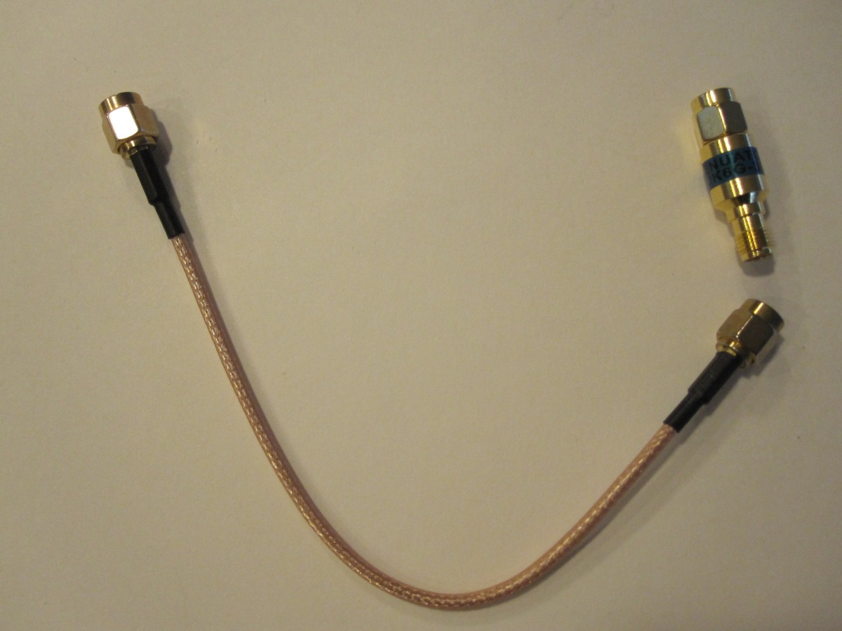
The cable is a common 10 to 20 cm SMA male to SMA male RG316 jumper pigtail.
Shown below is a close up picture of the cable and attenuator.
Program
YouTube Video of similar program and test execution.
- Make sure the Hermes-Lite is connected to the Raspberry Pi as described previously.
- Turn power on to the Raspberry Pi.
- Once the Raspberry Pi has booted, turn power on to the Hermes-Lite 2.0.
- Double-click on the desktop icon labeled Program.
- After 20 to 30 seconds, you should see a green SUCCESS message in the terminal window if all programming steps completed.
- Close the terminal window by clicking on the top-right X.
IMPORTANT: If programming does not complete within 1 minute, remove power from Hermes-Lite 2.0 unit quickly. Do not leave powered up for a long time (>5 minutes) without proper programming.
Test Flashed Gateware and Clock
After programming, power cycle the HL2 unit. This is to double-check that the gateware has been flashed to the EEPROM. The HL2 unit should have 2 LEDs, idle mode and link speed, IP assignment and radio HW status, solid. See the picture below to identify the LEDs as well as the LEDs wiki page.
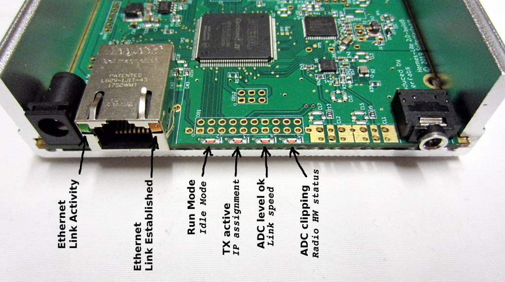
It is important that the radio HW status is on solid. If not, there may be an issue with the radio clock X2. If the LED is off, use an oscilliscope to verify that there is a clock. See the pictures below for probe points and expected signals. Note that this is a clipped sine wave oscillator so the output is only expected to be about 900mV peak to peak at 38.6 MHz. Check the soldering of X2, B57 and U6. Sometimes X2 is damaged by excessive heat during assembly and may need to be replaced.


Test
- If programming has completed successfully, double-click on the desktop icon labeled Test.
- Once the GUI opens, click Connect.
- Check to see that an IP address of 192.168.xxx.xxx was assigned.
- Click Test.
- The test will take approximately 90 seconds to execute. The longest part of the test is setting the bias. During that time, you will see messages in the text window just to the right of the Connect button.
- At the end of the test, any failing tests will be reported in the GUI as well as the terminal window. The final GUI for a successful passing unit is shown below.
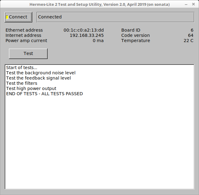
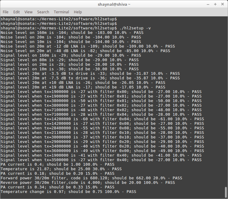
More detailed test output is seen in the terminal window. An example is shown below. Some failing tests will also identify board components to check.
Once programmed, you may rerun the test step multiple times without reprogramming if you need to debug any failing tests.
When done programming and testing the Hermes-Lite 2.0, power off the Hermes-Lite and remove all connections. Connect the next Hermes-Lite to test and power it on. The Raspberry Pi can remain on the entire time.