LEDs - softerhardware/Hermes-Lite2 GitHub Wiki
There are several LEDs which provide information about the Ethernet link and board status. From left to right, when viewing the front of the Hermes-Lite 2, there are:
Ethernet Connector CN3
- Green LED flashes when there is link activity. It is not necessarily activity to or from the Hermes-Lite 2, just activity on the link.
- Amber LED lights solid when a link is established. It is the same solid color for both 100Mbs and 1000Mbs links.
Onboard LEDs D2, D3, D4, D5
These LEDs operate in two modes. When software has connected to a HL2 and enabled run, the HL2 is in run mode and is transferring data with the host PC. When in run mode, the HL2 LEDs indicate basic operation information. When no software has connected to the HL2 or the HL2 is first powered up, then the HL2 is in idle mode. When in idle mode, the HL2 LEDs indicate various status.
Run Mode
- Run Mode or Idle Mode Network Subsystem
- Off. See the Idle Mode section below.
- On indicates that software has established a connection with the HL2 and set the HL2 to run mode.
- Flashing. See the Idle Mode section below.
- Transmit
- Off indicates the HL2 is not transmitting.
- On indicates the HL2 is transmitting.
- ADC Good Level
- Off indicates the HL2 ADC is seeing less than 75% of the available range.
- On indicates the HL2 ADC is seeing more than 75% of the available range. Adjust the LNA to see this LED on or flashing occasionally.
- ADC Clip
- Off indicates the HL2 ADC is not seeing maximum values.
- On indicates the HL2 ADC is seeing maximum values. Adjust the LNA to to see this LED rarely flash. Occasional flashes, 1-5 very short flashes per second, are okay.
Idle Mode
- Run Mode or Idle Mode Network Subsystem
- Off indicates a problem with the network subsystem such as no clock.
- On. See Run Mode section above.
- Flashing indicates the network subsystem is up and receiving the 25MHz ethernet phy clock.
- IP Assignment
- Off indicates IP assignment failure.
- On indicates IP assignment via DHCP was successful.
- Flashing indicates IP assignment via APIPA or fixed IP was successful. If DHCP was unsuccessful, APIPA assignment will be made after 15 seconds from HL2 power on.
- Link speed
- Off indicates no link or communication failure between the FPGA and U4 KSZ9031.
- On indicates 1000Mbs link established.
- Flashing indicates 100Mbs link established.
- Radio Subsystem
- Off indicates a problem with the radio subsystem such as no clock from the AD9866 or U6 (VersaClock5 IC) was not programmed successfully.
- On indicates radio subsystem clock is up and operating at the correct frequency.
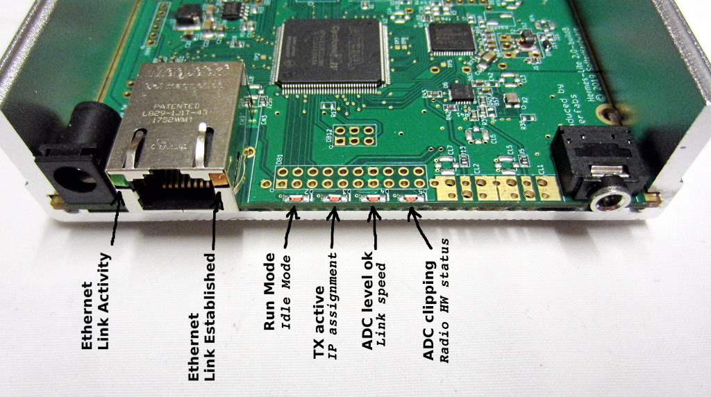
A summary of the LEDs meaning is in the picture below: