Final Assembly - softerhardware/Hermes-Lite2 GitHub Wiki
The Hermes-Lite 2.0 main board, the N2ADR filter companion board, and the recommended enclosure with end plates are available as 3 separate purchases. This is so you can mix and match and create the final radio that you desire. This wiki page walks you through the final assembly steps assuming you have purchased all 3 options.
Hermes-Lite 2.0 Main Board
Below is a picture of what is included with the Hermes-Lite 2.0 main board purchase. The heat sinks should be attached to the FPGA and AD9866 as seen in later pictures. The wire is optional and is included should you wish to rewind T3, the TX balun, for slighly more power as described in the Build8 Notes. This should not be needed for recent builds. The wire is special as it has thin insulation which can withstand heat.

N2ADR Filter Companion Board
In order to meet spurious emissions standards, the Hermes-Lite 2.0 must be used with adequate transmit filters. The N2ADR filter companion board fills this requirement. It attaches to the Hermes-Lite 2.0 with the included small 20x2 jumper board as seen in later pictures.

Recommend Enclosure and End Plates
Below is a picture of the recommended enclosure with end plates. If you do not use the recommended enclosure, then you must find some other means of adequately dissipating heat during transmit. The Hermes-Lite 2.0 main board can be used standalone for receive but must have additional heat sinking for full 5W transmit.

If you did not receive all of the pieces pictured, please e-mail service @ makerfabs.com and include your name, order number, preferred shipping address as well as a description of what is missing.
Assembly Procedure
In the standard configuration, the Hermes-Lite 2.0 relies on the aluminum enclosure for proper heat dissipation during full power transmit. This requires establishing good thermal contact between the bottom edge of the Hermes-Lite 2.0 main board near the PA with the board slot of the enclosure.
Drill Hole
There is one hole in the Hermes-Lite 2.0 board near the PA to provide some mechanical pressure between the board and the enclosure slot to improve thermal dissipation. This is a 3.3mm diameter for standard fit of M3 size hardware. Other similar hardware, including M2.5, M2 or imperial, may be used. You must supply an appropriate screw and nut. Most hardware stores have an ample selection.
First, as shown below, position your boards within half of the enclosure. Attach the end plates with screws so that the boards are properly positioned. Use a center punch and hammer as shown to mark the location to later drill a hole.

Drill a hole through the enclosure large enough for your screw. On the outside of the enclosure, countersink the hole so that the bottom remains flat. A large drill bit can be used to make the countersink.

Remove Enclosure Coating
The black coating on the enclosure is not a thermal conductor. For best results, sand or grind the slot near the PA slightly to remove this coating. Usually a few strokes of finer 100 to 200 grit sand paper is enough. It helps to use a thin metal ruler to support the sand paper. Also, a Dremel tool with a sanding disc will make quick work of this.


Apply Thermal Compound and Pressure
Finally, apply a thin layer of thermal grease/paste/compound between the Hermes-Lite 2.0 main board rail and the sanded portion of the slot. This further improves thermal dissipation. The thermal grease is not supplied, but is easily found on Amazon or at a computer store. It is the same thermal compound used to interface a heat sink to a computer processor. Below is an internal picture showing the boards in place with the screw and bolt providing some pressure. Also note that the two heat sinks are attached to the FPGA and AD9866.

Heat Shim
Be very careful when installing the heat shim as incorrect installation may cause shorts and destroy your Hermes-Lite 2.0! Look closely at the orientation pictures below. Don't use conductive thermal paste. If you have any doubts, do not use the heat shim and instead rely on the rail only for thermal dissipation.
Below are two pictures showing heat shim installation. Carefully note the shim orientation. A small amount of nonconductive thermal paste applied between shim and HL2 board contact as well as shim and enclosure contact is helpful. Slight sanding to remove the black coating on the inside of the enclosure where the shim will contact also improves heat transfer to the enclosure. Slide the heat shim and the Hermes-Lite 2 board into the enclosure at the same time. Use a small screwdriver as seen in the picture below to keep the PCB board hole aligned with the shim hole. Once enclosure, shim and PCB holes are aligned, use a M3 screw and nut to hold all in position and provide some pressure to all contacts.


The bevel on the heat shim provides extra clearance for components on the bottom side of the HL2 board near the heat shim. In particular, J31 and J32 as seen in the picture below may be shorted or stripped off the HL2 board if the heat shim is installed incorrectly or askew. Please check that J31 and J32 are not affected by the heat shim installation.

In most cases, a properly oriented heat shim is an easy fit with the standard 40mm tall enclosure. In some cases due to tolerance variations of the enclosure and/or heat shim, you may need to sand inside areas of the enclosure and the heat shim itself for a better fit. The heat shim design is here. This heat shim design only works with the 40mm tall enclosures.
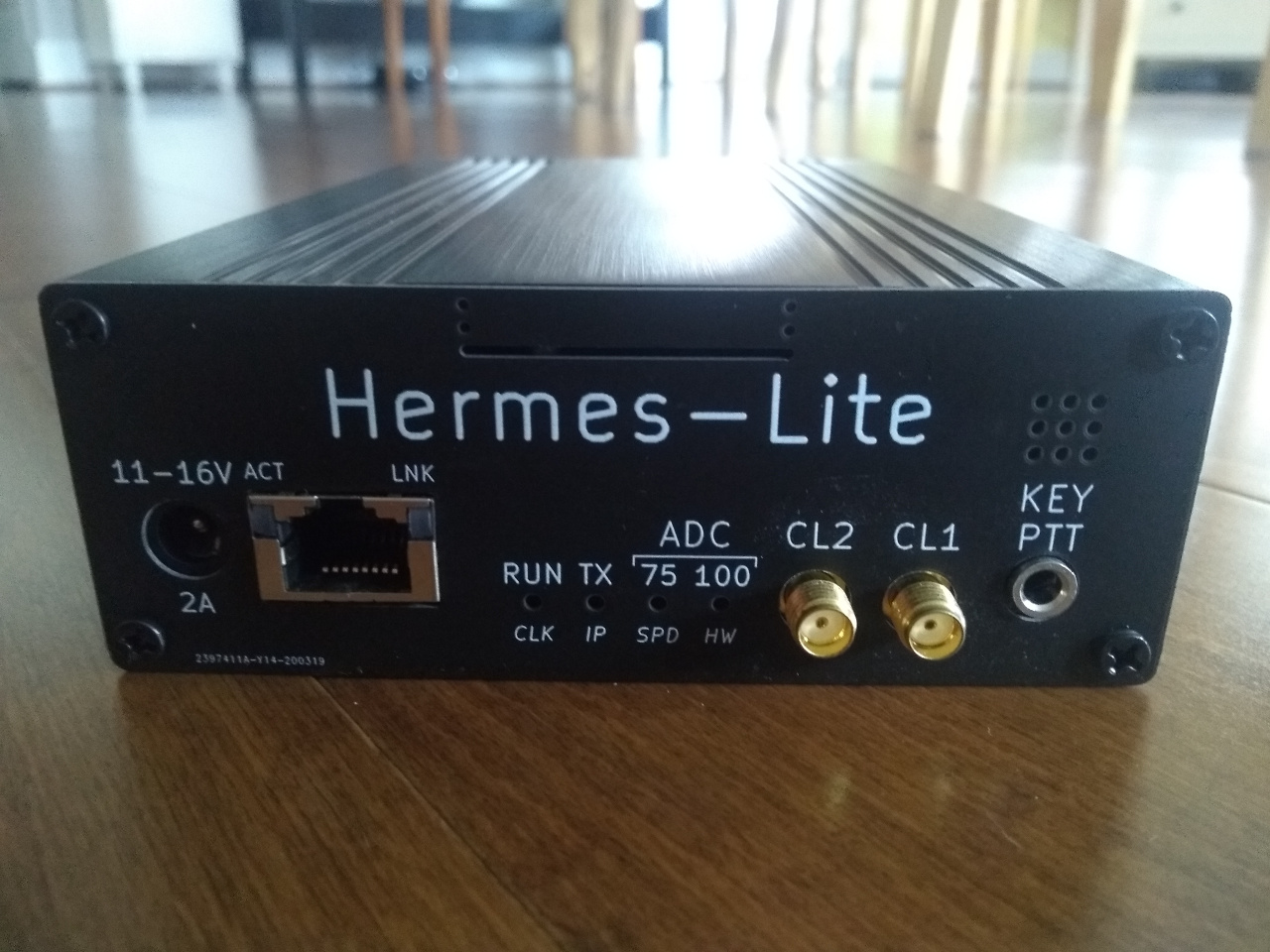
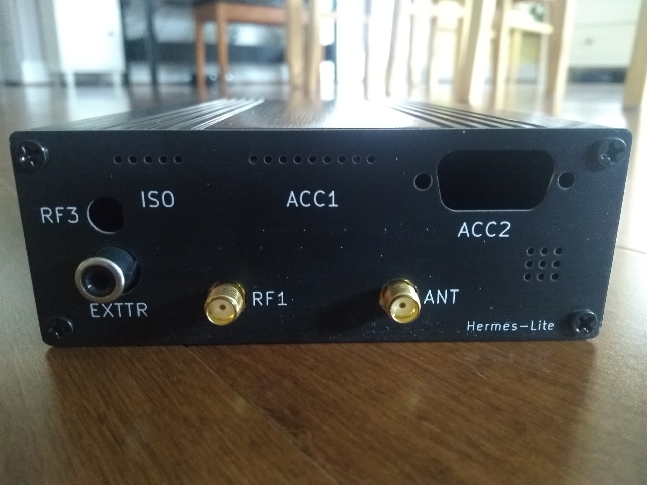
Attach End Plates
Now you can complete the unit and attach the front and rear end plates. The provided screws are intended to be countersunk and can be screwed in too tight to deform the end plates. Some people choose to substitute other screws.