Build8 Notes - softerhardware/Hermes-Lite2 GitHub Wiki
This page is for notes and modifications of build8 units.
Dented SMA Connectors
When heat sealing the ESD bag, some SMA connectors may have been dented. If you see this on your build8 unit, please send private e-mail to hermeslite @ gmail.com for replacement SMA units.
Low Power On 15,12 and 10M
User testing of Build8 units showed that PA power output was slightly lower than previous units. This was traced to several reasons:
- Longer length of T3 leads found by production house
- Fatter wire used on T3 meant windings weren't as close and tight
Several solutions and modifications were proposed:
- Remove T3 and shorten leads
- Remove T3 and rewind with other wire, short leads
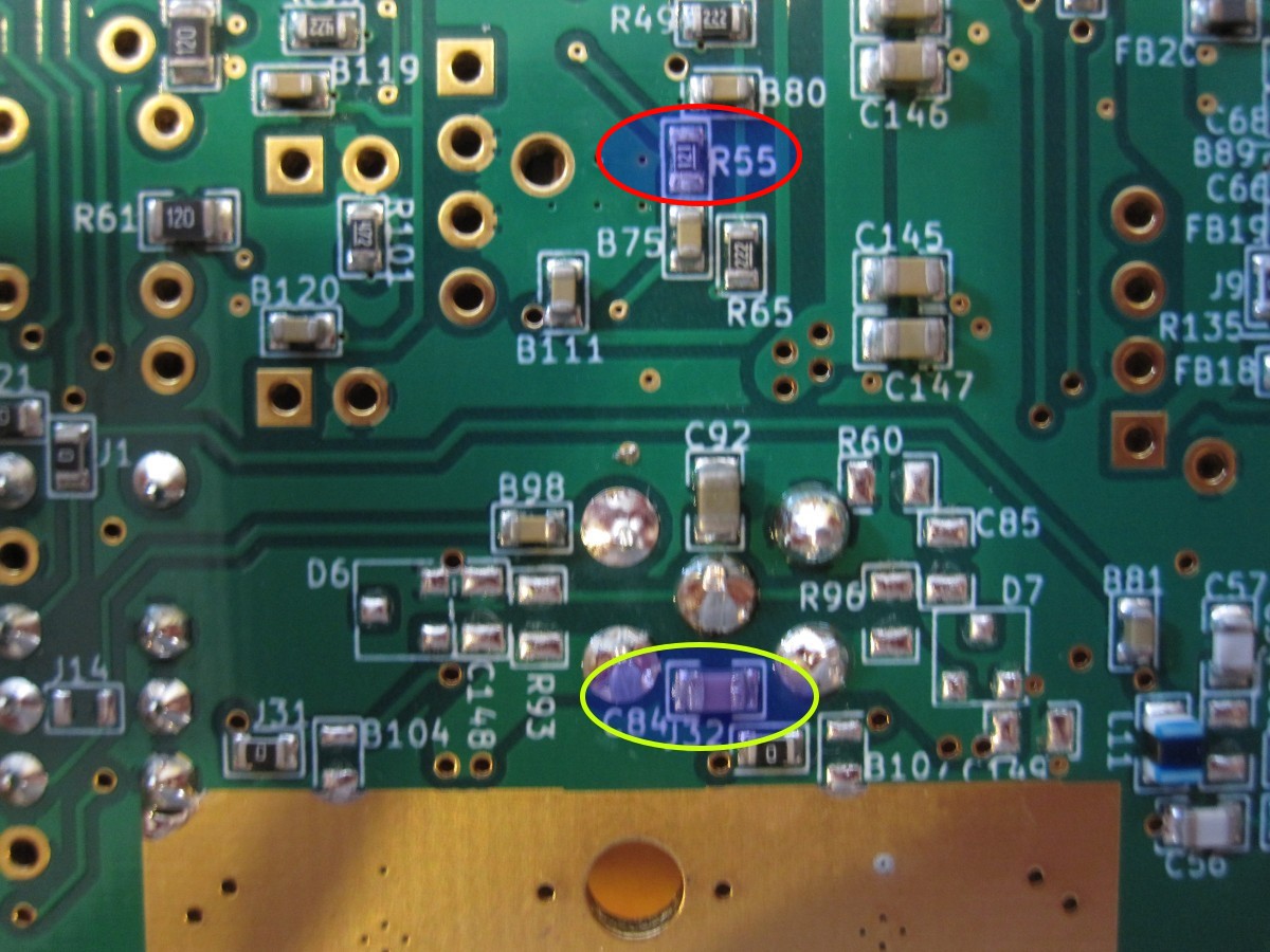
- Increase capacitance C84 by 150 pF
- Change R55 to 100 Ohm to increase driver output
The solutions should be tried in order listed.
If you purchased a build8 unit and wish to apply some or all of these modifications, please send private e-mail to hermeslite @ gmail.com and request a mod kit.
More details can be found in the google group links below and in the remainder of this wiki page.
TX Transmit Balun Winding
Two cores have been tested:
The B62152A4X30 core, which is used in the Build8 units, conducts and there have been problems when using enamel wire with this core. Use wire with high temperature insulation (PFTE/FEP) with this core. Some options are:
- FEP wire Junkosha AF04B050 (SA)
- 7*0.2 ptfe wire
- Solid silver wire 22AWG FPE
- Google Group link with wire used in previous builds and sent with kit
The mod kit includes ~35cm of wire. I measured 10.5cm required for the 4 windings and 3.7cm each for the two single windings, assuming 2.5mm is stripped.
Transformer Pin-Out
The T3 transformer pin numbers on the schematic and its PCB thru-hole connections location are shown in the following picture:
Note that the polarity between primary and secondary is not important, pins 4 and 5 on the primary can be swapped as well as pins 1 and 3 on the secondary.
When using the B62152A4X30 core, with a 4-turns winding and 1 turn plus 1 turn on the other winding the transformer windings connections will look like in the following drawing:
Below is the TX balun with 4 loops showing which holes the wire ends should be soldered to. Note that on the bottom of the core you count 3 turns going from hole to hole.
Below is a top view of the TX balun with 4 loops. Note that from this side you count 4 turns going from hole to hole.
The two single loops are shown below. First is the left and then the right.
First the four turn loop is wound, then the two single loops in any order. The TX balun with all loops should be soldered snuggly on to the PCB as seen below.
One way to complete the TX balun is to solder the two single loops first to the center power through hole as seen below. These wires should be about 3.5 to 4.5cm in length each.
Next, install the core with the four turn secondary wires going through the two holes farthest from the edge as seen below. One of the primary turns will go up through the left hole of the core, down the right hole and into the right hole of the PCB. The other primary turn will go up through the right hole of the core, down the left hole and into the left hole of the PCB.
Add 150pF to C84
In the picture below, C84 is circled in yellow on the bottom of the HL2 PCB. Place the 150pF 0805 capacitor provided in the kit on top of the existing capacitor and solder in place "piggy back" style. Do not remove the existing C84.
Increase PA Driver
In the picture above, R55 is circuled in red on the bottom of the HL2 PCB. Remove R55 and replace with the 100 Ohm resistor provided in the kit.


