External Connections - softerhardware/Hermes-Lite2 GitHub Wiki
This page walks through all the external connections for the Hermes-Lite 2.0.
Front
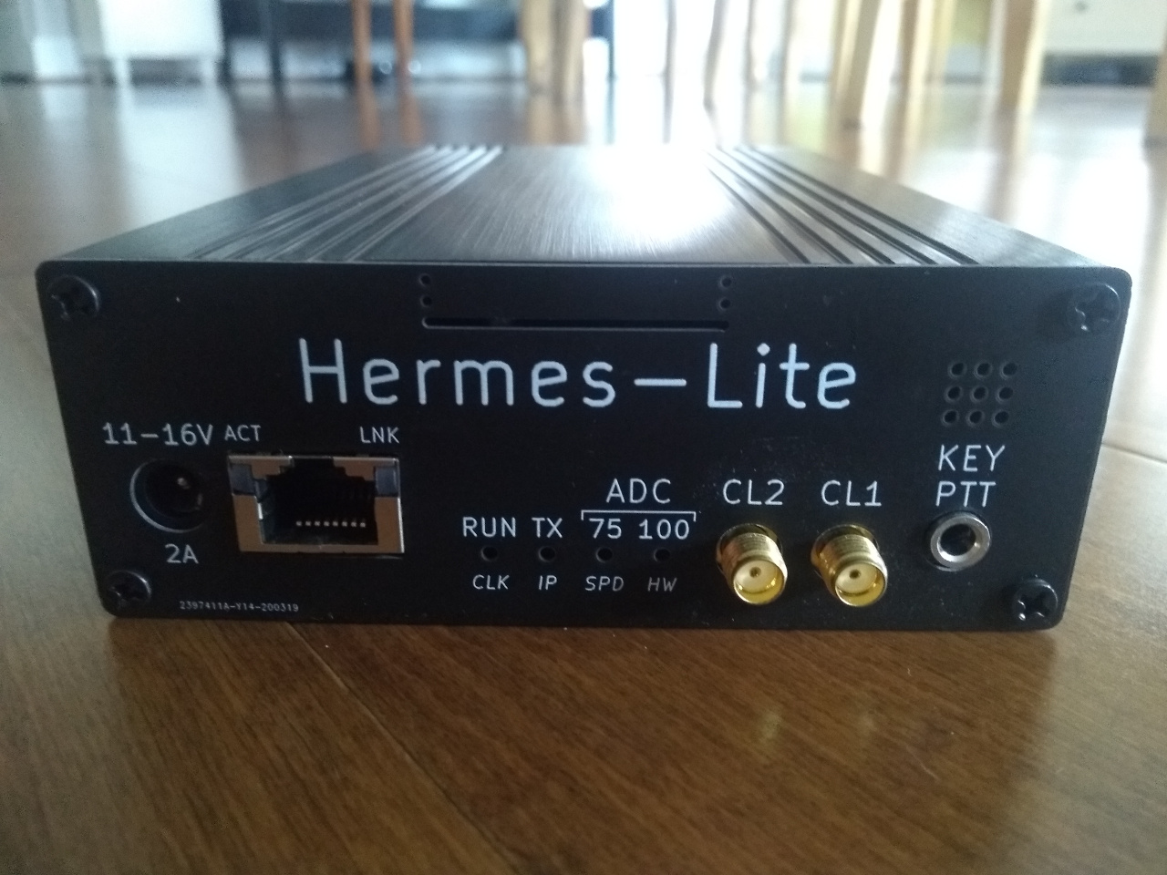
Power Supply
The Hermes-Lite 2.0 requires a 11 to 16 VDC power supply capable of supplying at least 2.0A. Although 11 to 16 VDC is supported, it is best to stay in the 12 to 13.8 VDC range. The supply input is protected against polarity inversion.
A 2.1mm center pin 5.5mm outer diameter barrel connector is expected to supply power to the Hermes-Lite 2.0; the positive terminal must be on the inside connection and the negative (ground) on the outer shell. If you don't have this connector, a inexpensive source of cable with the correct barrel connector is your local thrift store.
A low noise linear power supply should be used for best results, although many quality switching power supplies can be just as good. One way to test a power supply for noise is to measure the noise floor with no antenna using Quisk at maximum LNA gain of +48dB. A better power supply should result in a lower noise floor.
Ethernet
The Hermes-Lite 2.0 supports both 100Mbs and 1000Mbs ethernet connections via autosense. An ethernet connection is required for the Hermes-Lite 2.0 to work with software on your computer. The default configuration is for the Hermes-Lite 2.0 to be wired into your home network and to obtain an IP address from your DHCP server, usually part of your router.
More complex configuration such as a direct connection to your computer are possible. Quisk can be used to set a fixed IP address or alternate MAC, but it is best to assign a fixed IP address for the HL2 with your DHCP server based on the MAC.
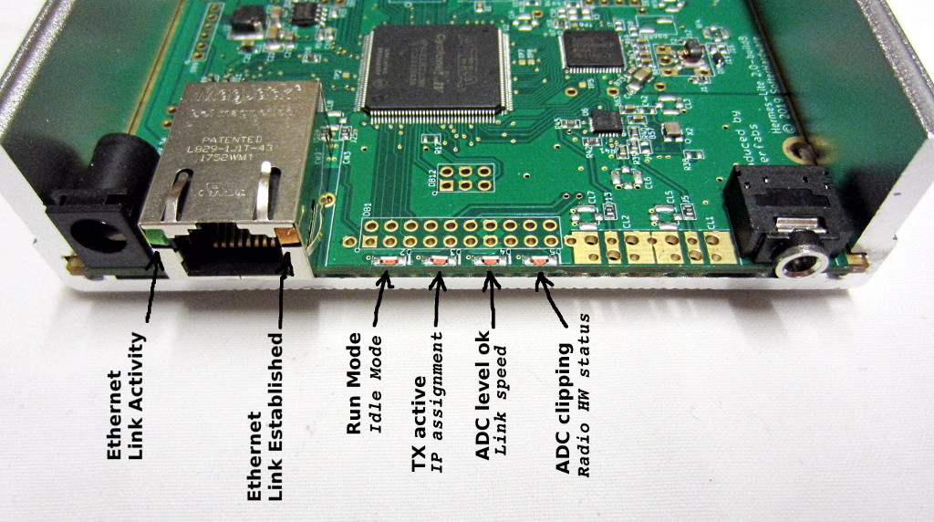
LEDs
There are several LEDs which provide information about the Ethernet link and board status. From left to right, when viewing the front of the Hermes-Lite 2, there are:
Ethernet Connector CN3
- Green LED flashes when there is link activity. It is not necessarily activity to or from the Hermes-Lite 2, just activity on the link.
- Amber LED lights solid when a link is established. It is the same solid color for both 100Mbs and 1000Mbs links.
Onboard LEDs D2, D3, D4, D5
These LEDs operate in two modes. When software has connected to a HL2 and enabled run, the HL2 is in run mode and is transferring data with the host PC. When in run mode, the HL2 LEDs indicate basic operation information. When no software has connected to the HL2 or the HL2 is first powered up, then the HL2 is in idle mode. When in idle mode, the HL2 LEDs indicate various status.
Run Mode
- Run Mode or Idle Mode Network Subsystem
- Off. See the Idle Mode section below.
- On indicates that software has established a connection with the HL2 and set the HL2 to run mode.
- Flashing. See the Idle Mode section below.
- Transmit
- Off indicates the HL2 is not transmitting.
- On indicates the HL2 is transmitting.
- ADC Good Level
- Off indicates the HL2 ADC is seeing less than 75% of the available range.
- On indicates the HL2 ADC is seeing more than 75% of the available range. Adjust the LNA to see this LED on or flashing occasionally.
- ADC Clip
- Off indicates the HL2 ADC is not seeing maximum values.
- On indicates the HL2 ADC is seeing maximum values. Adjust the LNA to to see this LED rarely flash. Occasional flashes, 1-5 very short flashes per second, are okay.
Idle Mode
- Run Mode or Idle Mode Network Subsystem
- Off indicates a problem with the network subsystem such as no clock.
- On. See Run Mode section above.
- Flashing indicates the network subsystem is up and receiving the 25MHz ethernet phy clock.
- IP Assignment
- Off indicates IP assignment failure.
- On indicates IP assignment via DHCP was successful.
- Flashing indicates IP assignment via APIPA or fixed IP was successful. If DHCP was unsuccessful, APIPA assignment will be made after 15 seconds from HL2 power on.
- Link speed
- Off indicates no link or communication failure between the FPGA and U4 KSZ9031.
- On indicates 1000Mbs link established.
- Flashing indicates 100Mbs link established.
- Radio Subsystem
- Off indicates a problem with the radio subsystem such as no clock from the AD9866 or U6 (VersaClock5 IC) was not programmed successfully.
- On indicates radio subsystem clock is up and operating at the correct frequency.
A summary of the LEDs meaning is in the picture below:
ADC LED Operation During Transmission
As above, two LEDs are used in Run Mode to show AGC operation:
- D4, labeled ADC-75/spd: ADC Level OK
- D5, labeled ADC-100/hw: ADC Clipping
The Hermes-Lite 2.0 always operates in full duplex mode whether or not software is making use of that mode. This means the receive path does pick up the transmitted signal and D4 (ADC-75) and D5 (ADC-100) LEDs can indicate RX clipping even during transmission.
If the LNA gain is at the default +14 to +20 dB range, then you will usually see clipping during transmit.
Some SDR applications reduce the receive LNA gain during transmission. This impacts if clipping occurs and thus whether the ADC LEDs activate during transmission.
PowerSDR, piHPSDR, LinHPSDR and perhaps other SDR applications have a separate setting for RX LNA gain (or attenuation from +20dB) and the software will switch to that gain setting during TX.
Quisk and perhaps other SDR applications makes use of the the hardware managed TX LNA gain as described on the protocol wiki page to set two gain levels and then let the HL2 do the switching. The hardware managed TX LNA gain is a HL2-specific protocol extension.
At this point in time, it appears that SDR Console does not change the LNA gain during transmission nor uses the hardware managed TX LNA gain and hence your clipping during TX.
One reason for these two gain levels is that PureSignal needs a clean signal from the RX ADC during transmission, not one with clipping.
External Clocks
The Hermes-Lite 2.0 has two external clock connections, CL1 and CL2. These are not used for basic operation, but are included for more advanced operation modes.
CL2 is a digital clock output. It can be used to connect to another HL2 to provide a master synchronous clock for coherent receive and transmit. It may also be used as the clock for transverter as it is tunable from 1 to 200 MHz.
CL1 is a digital clock input. It can be used to connect to another HL2 to receive a master synchronous clock for coherent receive and transmit. It may also be used to accept a GPS reference or other highly accurate frequency reference.
The Hermes-Lite 2.0 exposes full read and write configuration of the Versa5 5p49c5923 clock generator used for CL1 and CL2 to software.
Key PTT
The Hermes-Lite has a 3.5 mm stereo KEY/PTT jack on the front panel. The ring connector is the push-to-talk input. Ground it to put the Hermes-Lite into transmit mode. The tip connector is the key input. Ground it to put the Hermes-Lite into transmit mode and generate a CW signal. The Hermes-Lite does not have an internal keyer or sidetone, so connect your external keyer with sidetone or a straight key to the CN4 tip. Starting with gateware 71p2 you can connect a foot switch to the ring to turn on transmit and then key CW using the tip. Previously the functions were separate.
The ring and tip status are sent to the PC so that your SDR software can react to them. For details see the protocol page. The PC can also set transmit mode and send CW without using CN4. See the documentation for your SDR software.
In normal operation, software will trigger PTT or the CW KEY. Most operation is remote through the software, and the Hermes-Lite 2.0 can be at a remote location.
Vent
Above the Key PTT jack are 9 ventilation holes.
Cable Access
At the top of the front end plate is a slot with 2 holes on either end. This is for additional internal/external wiring if needed. You may snip along the 2 holes and remove a piece of the front end plate to make a larger access slot. A potential use for this is LVDS wire connections between radios to faciliate multiple coherent Hermes-Lite 2.0 units.
Rear
The rear end plate contains several openings for optional IO. More details can be found on the IO wiki page.
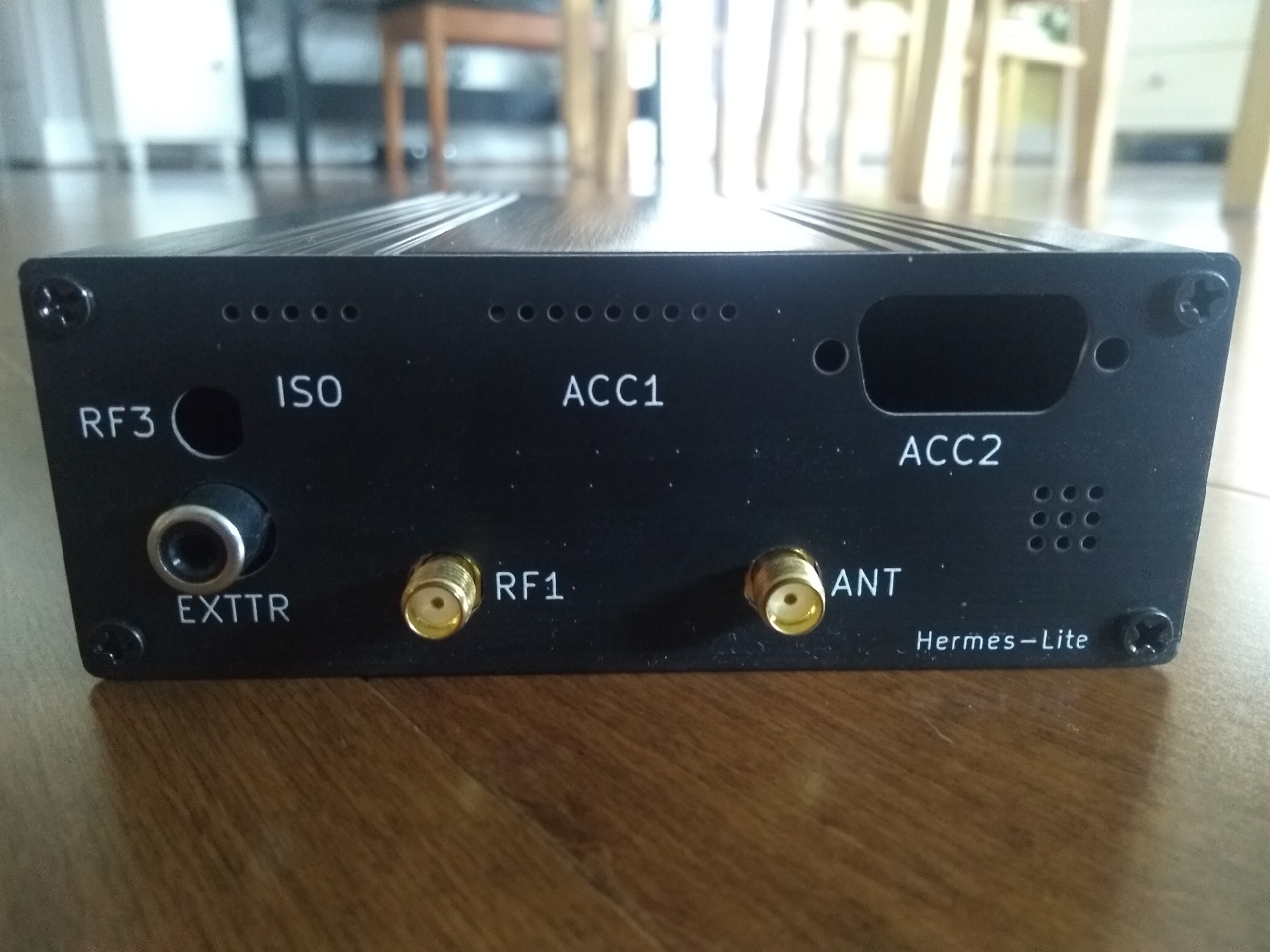
EXTTR
This is an "open collector" style output to turn on an external power amplifier for transmit. The center pin is pulled low by the HL2 during transmit. The ring is ground. An external PA should pullup the center pin with a resistor. The pin may be pulled up to 28V. Power should not exceed 1W, and should most often be much less than this. For example, don't exceed 80mA at 12V, so minimum pullup resistor of 150 Ohms. Typical pullup resistors will be in the 1K to 10K range.
RF1
This is the low power RF output, max 17dBm. It is used in full-duplex mode such as required for transverters. RF1 is the low power output and ANT becomes the dedicated receive input.
ANT
This is the primary antenna connection for both transmit and receive. The Hermes-Lite 2.0 contains an internal TR relay. It may also be used as a dedicated receive input in full-duplex mode. Software must put the Hermes-Lite 2.0 into full-duplex mode.
ACC2
This is for an optional DB-9 serial connector. The current gateware can send band selection data to a HR50 PA. See this page for more details.
ACC1
This is for an optional ATU connector. It may be a simple 0.1 inch space header or a terminal block. The current gateware can interface to an ICOM AH-4 or compatible ATU. See this link for more details.
ISO
This is for an optional optoisolator connection used for EER experiments. See this link and this link for more details.
RF3
This is for optional TX feedback to the RX to improve PureSignal. See this link for more details.