Enabling EER PWM Output - softerhardware/Hermes-Lite2 GitHub Wiki
Similarly to the original OpenHPSDR Hermes board, the Hermes-Lite 2.0 can be configured to provide a PWM-modulated output which follows the TX amplitude envelope. This can be used to implement a high-efficiency power amplifier using the Envelope Elimination and Restoration (EER) technique.
Some more details about EER can be found on the openHPSDR THOR project page (which unfortunately has been stagnant for some time) and in these lecture notes.
F6ITU has also created a GitHub repository with some EER-related projects from various hams which can be used as starting point for experimenting.
To enable the TX PWM envelope functionality, currently the Hermes Lite 2.0 has to be reprogrammed with a specific gateware: in the standard gateware release this functionality is disabled in order to save FPGA resources. If the EER-enabled gateware is not included in the gateware release directory, please ask on the Hermes-Lite Google Group.
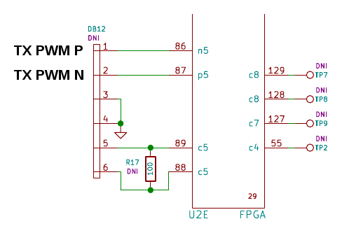
Once the EER-enabled gateware is loaded and the EER output enabled via SW, the envelope PWM output will be available on FPGA pins 87 and 86, originally reserved for an optional LVDS bus.
On the Hermes-Lite 2.0 build 8 these pins are connected to the DB12 connector, as shown below: DB12 pin 2 (FPGA pin 87) is the normal envelope PWM output and DB12 pin 1 (FPGA pin 86) is the same signal but inverted (this can be useful for additional filtering or other). Note that those pins are directly connected to the FPGA so care should be take to avoid overstressing them.
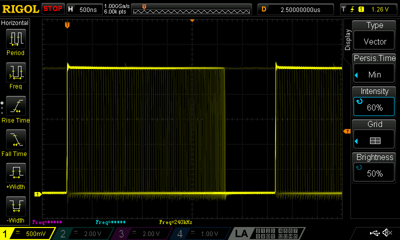
The PWM output is a fixed frequency pulse train at 240 kHz with a variable duty cycle from (theoretically) 0 % to 100 % in 1024 steps (so 10 bit resolution). The output high level is 2.5 V and the low level is 0 V with a nominal maximum current of 8 mA.
Here is a scope screenshot of the PWM output when transmitting a two-tone signal:
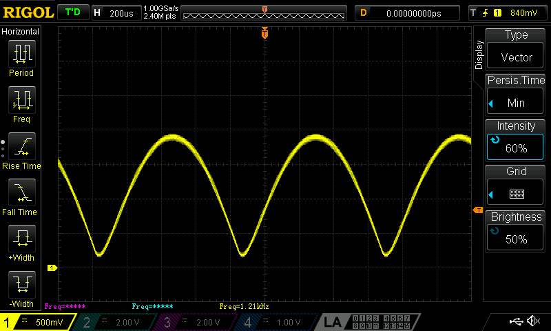
and here is the same signal after low-pass filtering:
where the two-tone signal envelope is accurately reconstructed.
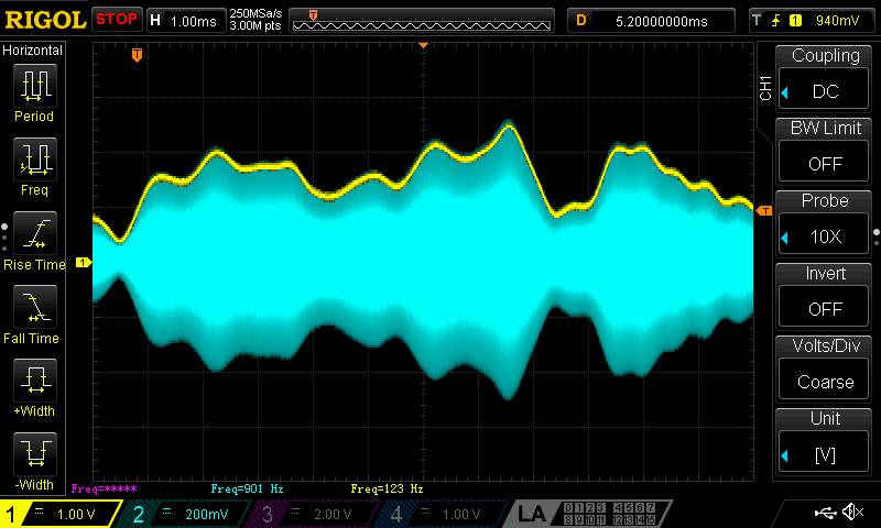
An example with a more complex modulation waveform (short section of speech) is shown in the picture below; the blue trace is the RF output and the yellow trace is the filtered PWM envelope output.
again, the filtered PWM envelope output closely follows the RF envelope.
Note that the RF and PWM outputs delays need to be matched by using the appropriate SW controls, as described below.
Software
To enable the TX envelope PWM output and set its various parameters the SW application used to control the Hermes-Lite 2.0 must make the appropriate controls available. The two main SDR applications which can also manage the EER functionality are PowerSDR and linhpsdr.
Software settings
The main TX envelope PWM output parameters are set in a dedicated configuration tab, which is very similar in the two SWs:
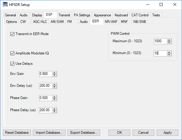
this is the PowerSDR EER setup window:
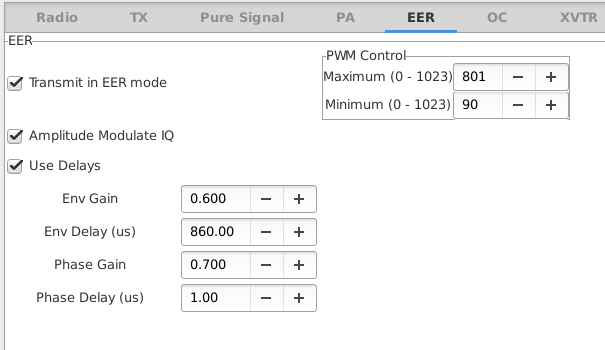
and this is the same in linhpsdr:
To enable the PWM output, the "Transmit in EER mode" checkbox must checked.
The "Amplitude Modulate IQ" checkbox controls whether the RF output will have the usual amplitude and phase modulation (checked) or will provide just a constant amplitude sinewave with phase modulation only (unchecked).
In any case the RF output amplitude is scaled by the "Phase Gain" factor while the signal used to modulate the PWM output is scaled by the "Env Gain" factor.
"Env Delay" add a delay to the PWM output and "Phase Delay" to the RF output for matching the respective paths delays.
In the "PWM Control" frame the minimum and maximum PWM output can be set, for example to keep some minimum voltage on the output stage.
