Soldering - rittme/nrfmicro GitHub Wiki
Please don't miss the Soldering#testing section about testing the soldering on the module, it's super important!
Guides
- https://likipiki.gitlab.io/posts/nrfbuild/ Гайд по сборке NRFMicro 1.4 (russian)
- Getting nRFMicro to work (from https://rmi-kb.com)
USB connector
USB connector solders just fine with a drag-soldering technique. Spread a small amount of flux paste over the pins and slowly drag the solder tip with a small amount of solder over them. You don't even really need to drag, just touch them up a little, it's better to not apply lateral force to the USB-C pins, they are super flimsy. Remove excess solder with an iron tip.
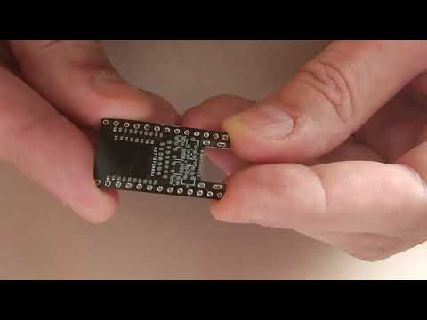
Bluetooth module
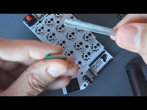
Trimming the module
Modules might need sanding off ~0.1 mm from the sides before soldering. They are a little bit too wide (picture) to fit between two PLC headers when the board is flipped.
Soldering the module
Inner pads use through-holes for hand-soldering. Pre-tin and flux all the pads both on the module and the PCB. Use solder wick to remove excess solder and level the module. After soldering the outer pads, add solder to the inner pads from the other side. If there's no connection, reach the pad with a fine soldering tip (e.g. T12-ILS) through the hole and add more solder and flux if needed (you can also use a thin wire, e.g. diode leg to scrape the pad surface via the hole, it usually helps).
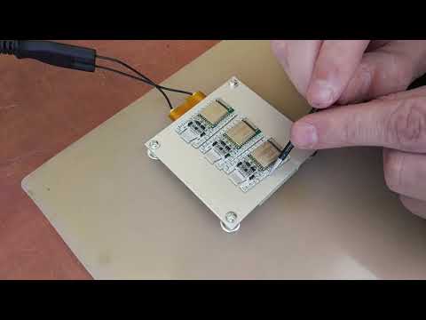
Soldering with a stencil and a hot air gun (nRFMicro 1.3):
My latest way to solder the modules is to use stencil, soldering paste and a hot air reflow gun but I still have to fix all the inner pads with T12-ILS tip because hot air gun can't heat up the PCB evenly so it ends resting on a cold paste underneath. You can use either a reflow oven or a heating plate, you won't need to fix the board then.
Soldering with a BGA Demolition device (nRFMicro 1.4):
Connect Underpads
If you think the underpad solder is not touching, you can try this:
- Find a piece of fine wire (single core enamel works best).
- Add some flux
- Poke into the hole, heat it up and wiggle around, that should bridge the pads together.
I use this method to solve some of my connection issue and it works out quite well, make sure you do it quick and dont heat the pad too long, you might kill the module / that IO pin. Personally I try not to heat a joint more than 5 seconds. (source)
The key here is to transfer the heat (and the solder) to the underside pad, you can't do that if there's a air gap.
Unshielding the module
Bluetooth module shielding is taller than everything else on the board, except top-mount USB-C. With the midmount USB-C, shielding adds about 1.15 mm overall, that's quite a lot (picture), see Home for height comparison. I usually stick tweezers into one of the corners and use them as a tension wrench, then heat shielding with a hot air gun and remove it from the board.
Testing
Testing GPIO pins
Multimeter
This test actually tests soldering quality. DON'T power up the module! You can test inner pads with a multimeter in a DIODE mode (NOT the continuity mode!). Disconnect the power source, put red (!) probe on any ground pad, and black probe goes to the pad you want to test. Multimeter shows 0.6-0.9V drop voltage if the pad is connected firmly to GPIO, 0 indicates bad soldering, 0.01 is shorted to ground. You can test all GPIO pins this way.

Testing power circuit
Connect USB-C and check the battery charger using pads at the very top, B- (square pad) and B+ (round pad) without connecting the battery, there should be about 4.2V. Red LED (if present) is usually on or flashing. Blue LED is usually off (it's controlled by the user firmware). You can also check voltage between GND and VCC pin there should be 3.3V.
Note that in revision 1.3 charging voltage and output voltage should be explicitly enabled in firmware, so voltages may be off. The only way to check 1.3 voltages is to upload firmware that sets POWER_PIN and PROG_PIN to ground (see Pinout article).
When something's wrong it's mostly charger (it fries first, usually after reverse polarity), try replacing the charger (TP4054).
Test firmware
You can use this firmware file to test GPIO (you need to flash the bootloader first, see Bootloader article):
- blink.uf2 (precompiled binary from blink.c source code, double reset and copy to the internal USB drive)
Note that blinker only blinks on nRFMicro-related GPIOs, it doesn't blink on ALL GPIOs, so it can't be used for other boards.
Use any spare through-hole LED for testing. Connect LED+ to VCC pin and test all the Pro Micro GPIO pins consequently via 1K resistor. If it doesn't blink, it's mostly bad soldering on the underside pads. To reach underside pads through the holes, use fine soldering tip (such as T12-ILS) or a piece of copper wire, add more flux, add more solder, and heat them well to fill the gaps.
Handmade stencil
You can download .svg files for the handmade stencil in the releases section. Try printing from inkscape to match the scale.
There are also .stl ones (made with KiKit), you can try printing them in 3d but it doesn't always end well even on DLP printers with layer 0.15. FDM printers need some tuning but it sometimes work with 0.4/0.2 nozzle and layer 0.12.
You can also order a stencil on JLCPCB (additional $7). JLCPCB and other fabs just take F.Paste layer from the gerber files and don't need .svg files.
How to etch your own stencil:
- https://lowpowerlab.com/2013/02/11/diy-smd-metal-stencils-the-definitive-tutorial DIY SMD metal stencils (text)
- https://youtu.be/JWUJtmgh55M DIY stencil tutorial (video)
You can remove paint from the outer layer of the aluminum can using a hard sponge (video), then use magazine paper for toner transfer. Do not afraid to scratch the aluminum, toner will stick to anything. You can leave the inner layer coated and save on scotch tape. For etching I'm using solution made from hydrogen peroxide, citric acid and salt, it works fine with aluminum.
Equipment
My Tools
- https://www.aliexpress.com/item/1005001323205364.html Bakon 950d I use (tips I use are T12-K, T12-D24, T12-ILS)
- https://www.aliexpress.com/item/32884093657.html Mastech MS8229 (expensive, see any multimeter with diode mode)
- https://www.aliexpress.com/item/1005002074028476.html "BGA Demolition plate", 220V/50Hz, 260+/-10 C, works great
- https://www.aliexpress.com/item/1005001868376803.html SH72, cheap $11 soldering iron (T13 tips, needs 12-24V PSU)
- https://pine64.com/product/pinecil-smart-mini-portable-soldering-iron has both USB-C and DC, supports QC/PD/DC.
- https://www.aliexpress.com/item/1005002253807041.html Chinese JBC station $50 clone (uses superfine T210 tips)
- https://www.aliexpress.com/item/32921622250.html Kaisi 8858 Fan (PSU built in), also search for 8858 sort by price
I use NC-559-ASM flux (it apparently has 2M resistance but I had no problems), and Indium 0.5 mm solder (SN62/PB36/AG2). My irons (I'm mostly using Bakon T12 and JBC T210, don't really like the other ones):

Pinecil
Regarding Pinecil iron: https://wiki.pine64.org/wiki/Pinecil After some heated discussion on the discussion group, it was decided that it would be downgraded to 12-21V. Pinecil DC goes through USB-PD which is rated to 21V max. There's a hardware mod, you just need to cut one trace on the PCB, and then you will have a 24V capable Pinecil. Cut the trace in one spot anywhere between the red arrows and you will have a 24V Pinecil, see photo here (discord).
References
- https://github.com/joric/nrfmicro/issues/39 (LED polarity explained)
- https://github.com/makermoekoe/Hotplate-Soldering-Iron (Alternative hotplate, hacky but interesting)