installation - rfrht/FT991A-PAT GitHub Wiki
Install
First, prepare the tap of signals of interest coming from the radio. We will tap, namely:
- IF signal
- USB data
- TX9
- 5V
- 13.8V
Preparing Voltage and TX9 terminals.
As these signals does not require any special filtering, use a Female Jumper Cable terminal.
13.8 V
Use this exact side of the component to tap the 13.8V power - it is at the load side of the fuse. If something goes wrong with your board, it will blow the fuse, instead of blowing your radio 13.8V line. And we don't want it.
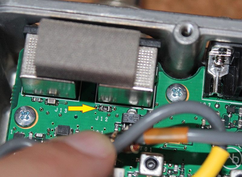
FT-991/A 13.8V tap point
5 V
Use the test point right after the connector - it is a small solder blob next to the connector.
The 5V line is indicated in the picture for reference only: Do not tap from the connector! Use the test point depicted in the next picture!
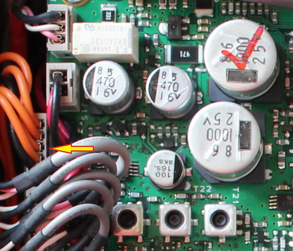
FT-991/A 5V connector - Third lead from bottom to top
Solder your 5V line to the test point
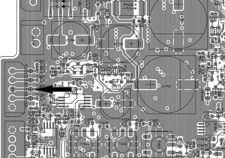
FT-991/A 5V tap point - Use the solder pad Test Point
TX9
The TX9 signal causes the panadapter board to disconnect from the IF line during transmissions, in order to avoid (or mitigate) possibly strong signals in the SDR with potential damage.
The signal is tapped from the Main Unit, and it causes the RF Switch to flip open, essentially disconnecting the SDR from the IF line during transmissions.
This signal is tapped close to the 13.8V tap point and close/underneath a internal coaxial cable. Thanks to Ian M7WMT for pointing it.
TX9 signal tap location - click to enlarge
FT-991 IF
If you have a FT-991 (non-A), you will also need to tap the signal using solder. Do it properly. Use a coax cable, be sure to ground it and tap the signal as per below schematic:
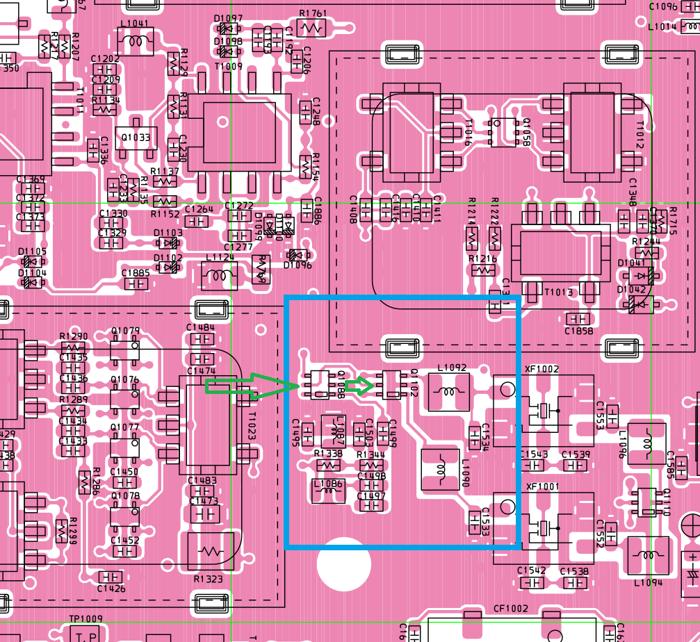
FT-991 (non-A) IF tap point schematic
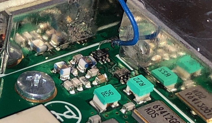
FT-991 (Non-A) IF tap point picture - In this sample, N5NXZ chosen to tap from the first RF switch. Notice that due to picture angle, it might suggest that he tapped the edge pin - it is not, it is the middle pin.
Andreas DM7AK chosen the second RF switch to tap the signal and was kind enough to provide pictures as well. Here's how he did it:

FT-991 (Non-A) tap from the second RF switch. Image credits: Andreas, DM7AK

RF switch tap point location. Image credits: Andreas, DM7AK
FT-991A IF
If you own a 991A model, then just plug a U.FL coax cable to the Scope unit port (J26):
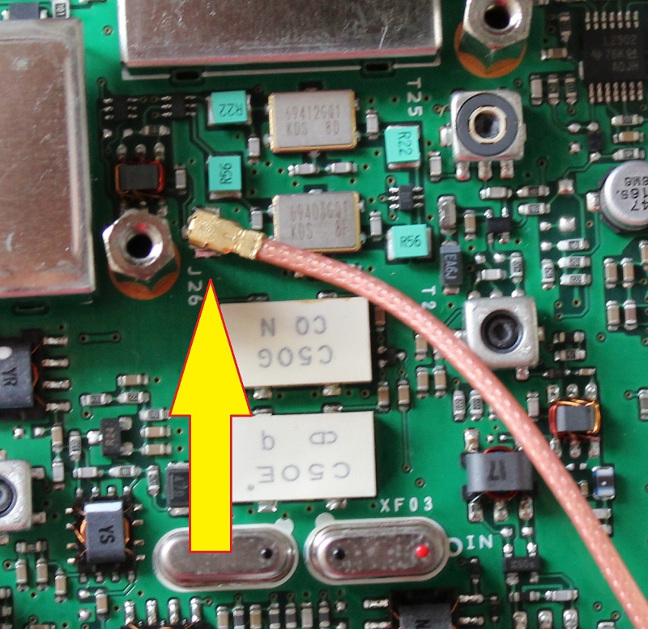
FT-991A IF tap point
SDR
The RTL-SDR will not fit inside the radio as is with its aluminum cover, USB and SMA connector. You will need to strip it out entirely and get to the bare board.
- Solder a rather long (~15 cm) coax cable terminated with a U.FL connector where it had a SMA connector.
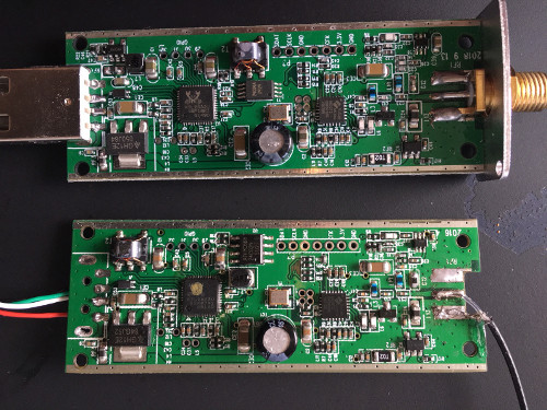
RTL-SDR Comparison. Yup, the coax soldering is horrid. Fortunately, Yvo reworked and did a decent and good one.
- Take a decently shielded USB cable and use it to solder its four leads to the GPIO ports. Solder the braid to some GND pad in the board. Notice the color sequence and the GPIO numbers!
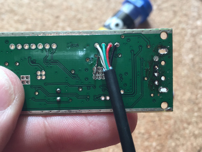
GPIO soldering (only in Full version, ==>> not needed in Lite version <<==)
-
Take another string of the USB cable and solder the connector where it used to have a USB connector. Solder only the white (USBDP), green (USBDM) and the shield. Leave black and red unused. Leave the gun. Take the cannoli.
-
Solder a male Jumper Cable Connector to the +5V lead.
-
Solder a thick cable to some large ground pad in the SDR (hint: The holes where the USB connector were soldered).
-
Use Kapton tape to isolate your SDR, while leaving the edges exposed, since they are ground connections:


- Wrap your dongle with copper tape. You should have something like this:
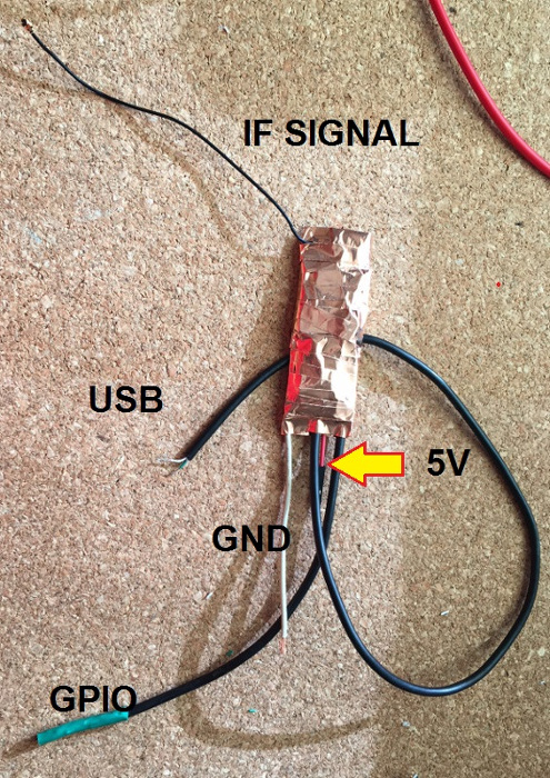
RTL-SDR with the needed connections
Connecting
- Now it is only (grins) matter of connecting everything together.
- Mount back the SCP Unit. Do not connect the IF in back to the J26.
- Connect Main Unit's IF tap to the panadapter
IF INconnector. - Connect the SCP unit
IFsignal to theSCP OUTconnector on the Panadapter. - Connect the 13.8V line to the female connector.
The SDR rest nicely near the front panel, over the flat cables.
- Put the SDR at the desired position. Connect to the nearby 5V line.
- Unscrew a bit the nearby Main Unit screw and screw the GND cable to this screw, in order to secure a good ground connection.
- Route the IF signal coax following the ATU unit to the panadapter board.
IMPORTANT
Do not route the power, USB etc. cables close to the Main Unit board. Avoid it, as it can induce noise to the receive stage of the radio. Try to move the cables over the shield cans, as aerial as possible. Do not let them lie close to the board, the radio might pickup noise!!!!
Some Full Version Remarks (doesn't apply to the Lite Version)
- Route the GPIO cable and solder the respective GPIO cables to the
BYP,BPFandDISpads. Remember to take note of which color/wire comes from its respective pad in the RTL-SDR, so you can manipulate it via the RTL-SDR GPIO Control. - If you want your Panadapter board disabled by default, wire the
DISline to the SDR's GPIO pin 30 (GPIO 4). Reason: This pin is high by default, essentially disabling the panadapter by default. In order to enable the panadapter board, you will have to deliberately turn this pin off/low. For more information, refer to RTL-SDR GPIO Control guide. - You are not required to wire them all - None of them are required for board basic functionality. If you are not using the Amp Bypass, the BPF or the selectable Disable, spare yourself the hassle and stick to the Lite Edition.
- If you went the Full Version route (and I'd love to hear your impressions), ensure to add a small patch of electrical tape, kapton, whatever isolation material covering the single RF switch at the top of the board. The radio bottom cover has an electrically conductive cushion that will touch the board and could short the RF switch leads - and that's no good. Refer to the below picture - I covered mine with electrical tape and done deal.
Panadapter and SDR Installed in FT-991A
It's DONE!
Check and re-check every connection. If you have any questions, file a Github issue or contact me (I'm good on QRZ.com).
At this point, you have completed the journey and (should have) a working Panadapter in your radio! \o/
I'm positive that you did the obvious tests, dry runs and is now ready to turn on the radio, no magic smoke will come out of it and this is what will happen when you plug the USB port to your computer:
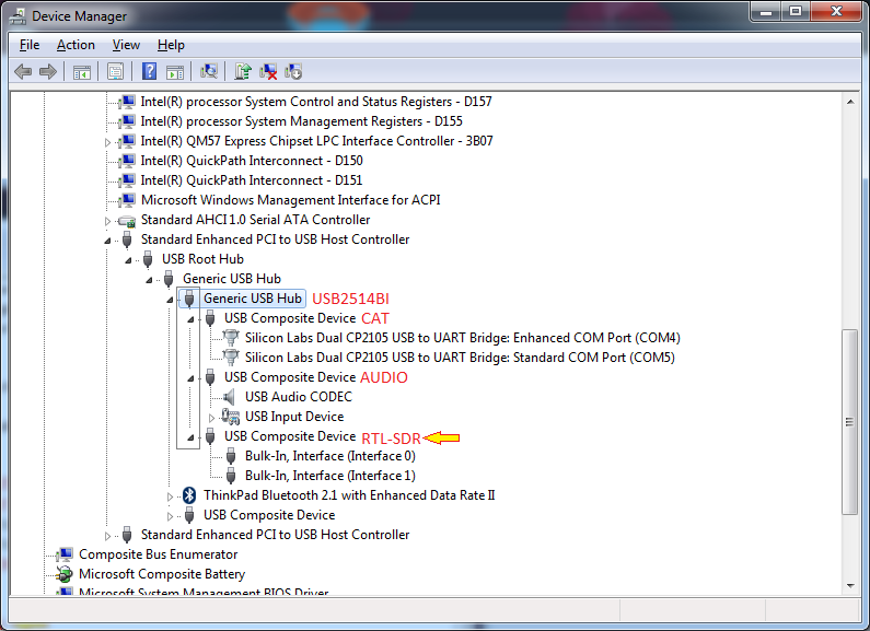
USB Enumeration of the Radio containing the Panadapter
In order to see this tree, open the Device Manager, select View and select Devices by connection.
Navigate the device tree to find the devices.
