appendix assembly variations - rfrht/FT991A-PAT GitHub Wiki
Where to lodge / mount / assemble it?
While the primary project aim was to integrate the SDR seamlessly inside the radio, there are some other assembly variations that might suit better your milleage. In order of simplicity, those are the options:
1. Panadapter in the radio, SDR in the outside

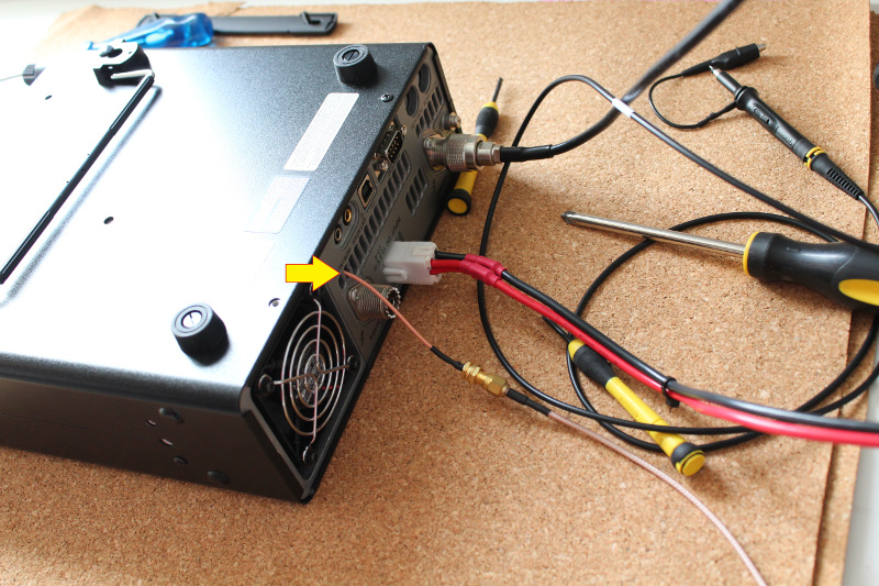
FT-991/A with external FI port
This is by far the simplest and least intrusive design. Actually, this was my first implementation to assure that everything was indeed working. All it takes is tapping 13.8V from the radio, installing the panadapter board and installing an extension cable with the IF signal outside the radio.
Pros:
- You have the ability to deploy any SDR better than the RTL-SDR to your radio
- Very simple and minimum modification and effort required.
- Works nicely as a proof of concept and for wetting your toes in the project.
Cons:
- Extra cable coming out of the radio
- Ground loop risk
- Risk introducing external signal in your radio receive chain
- The cable might radiate RF inside the radio (*)
- Needs choking in the FI cable (*)
(*) - These can be mitigated if you attach an SMA flange connector to your radio chassis. Just like Andreas DM7AK did:

2. Panadapter and SDR in the radio, external USB connection

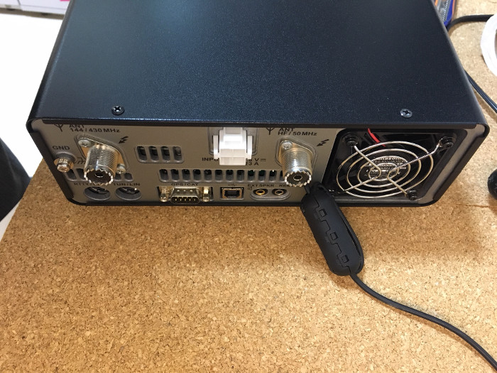
FT-991/A - SDR lodged inside the radio, SDR's USB cable coming out of the radio. Notice the 1-wind clip-on ferrite choke.
In this scenario, the panadapter and the SDR are lodged inside the radio - the only cable coming out of the radio is the USB cable that you will connect to your computer. The FI signal is contained inside the radio and not subjected to introducing noise to your radio RX block.
Pros:
- Pretty simple to deploy though requires some extra care when deploying the SDR inside the radio
- IF signal contained inside the radio, without external disturbances
Cons:
- External cable coming out of the radio
- Needs choking on the USB cable - otherwise the SDR goes out when you TX
- Ground loop risk
3. Panadapter and SDR in the radio, internal USB connection

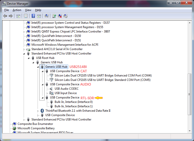
FT-991/A, with replaced USB controller, USB lodged inside the radio - SDR is exposed by the radio's USB port, without extra wires coming out of it. Radio externally looks like stock.
This the final objective - and when things gets an order of magnitude more complex. This requires the replacement of the radio's USB hub, a super picky QFN solder - but by far with the most rewarding results.
Pros:
- Clean setup, no external cables coming out of the radio
- No risk inserting external noise into the radio
Cons:
- Way more complex: Requires replacing a Main Unit QFN IC (Which can be done easily (less than 5 minutes) by your local radio repair expert, though). Discussed in more details in an specific chart describing it.