Custom Sensors - osrf/mbzirc GitHub Wiki
This page provides documentation on 3 methods of integrating a custom sensor in the MBZIRC simulator:
- Customize sensor parameters
- Create a new custom sensor implementation
- Adapt existing sensor to simulate a custom one
Before diving into the different methods, here is an overview of the components in the simulator related to custom sensor integration:
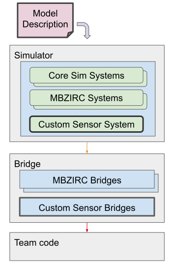
- Model Description: Description of the sensor model, including visual, collision, joint, and sensor properties.
- Custom Sensor System: A plugin for the simulator that custom sensor implementation lives. It is responsible for modeling, generating and publishing sensor data.
- Custom Sensor Bridge: Bridges Ignition data published by the simulator (from the custom sensor system) to ROS.
Throughout this page, we will show your how to create or adapt model descriptions, implement custom sensors, and add new bridges for your sensor data.
The first method is to customize parameters of existing sensors. If your custom sensor operates in a similar manner to one of the existing sensors available in the MBZIRC simulator, we recommend choosing this approach as opposed to implementing an entirely new one. For example, if you have a Time-Of-Flight sensor, you can consider simulating this using a lidar sensor.
The MBZIRC simulator provides 2 lidar models: 2D planar and 3D lidars. They can be found in the mbzirc_ign/models/sensors directory. The two lidar models are simulated using the same sensor type called gpu_ray but with different parameters. You can take a look at the model.sdf file in one of the lidar models to see its parameters. The description of the parameters can be found in the sdformat specification page for a sensor element
For any new sensor models to be included in the MBZIRC simulator, you will need to add a new package with the model to the mbzirc_custom directory. We will illustrate the process of adding a new sensor with custom parameters using an example point lidar model:
-
First, we have a mzbzirc_point_lidar package in the mbzirc_custom directory.
-
The CMakeLists.txt has a command to install the model in this package.
- Note that the
installcalls are currently commented out for example sensor models.
- Note that the
-
The actual model description files need to be placed in the mbzirc_custom/mbzirc_point_lidar/models/sensors subdirectory.
- Note: the
models/sensorsdirectory structure is necessary as the simulator will look into this path for sensors. In our example, the model name is mbzirc_point_lidar which is the same as the package name.
- Note: the
-
There are files in the model description directory:
- model.sdf: Model description in SDF format.
- model.config: Meta information about the model in XML format.
You can copy these model description files from either mbzirc_planar_lidar or mbzirc_3d_lidar. Make sure to update the fields in
model.confgand customize the sensor parameters inmodel.sdf.In the single point lidar example, we have these sensor parameters:
<sensor name="lidar" type="gpu_ray">
    <update_rate>20</update_rate>
    <lidar>
        <scan>
            <horizontal>
                <samples>1</samples>
                <resolution>1</resolution>
                <min_angle>0.0</min_angle>
                <max_angle>0.0</max_angle>
            </horizontal>
        </scan>
        <range>
            <min>0.05</min>
            <max>40</max>
            <resolution>0.01</resolution>
        </range>
        <noise>
            <type>gaussian</type>
            <mean>0</mean>
            <stddev>0.01</stddev>
        </noise>
    </lidar>
</sensor>
There are a few changes from the planar / 3d lidar models's
model.sdffile:- The
<samples>parameter is changed to 1 and the<min_angle>and<max_angle>are now both at 0 radians. This gives us a forward looking point lidar with a single range output. - The entire
<vertical>block is removed as they are not needed for a point lidar. - The max range distance is updated to 40m
- The update rate is set to 20Hz
-
The last step is to bridge the lidar data from Ignition to ROS. Because the simulator's launch script does not know our custom sensor package is a lidar model, it does not know how to bridge the data generated. Therefore, we will need to provide it with a custom Launch file for bridging the lidar scan and point cloud data. The simulator will look for a
launch/bridge.launch.pyfile in all custom sensor packages, and if it exists, the launch file will be included as part of the process for spawning a robot into simulation. In our example, we have a launch/bridge.launch.py file for bringing up the lidar bridge node process.- In the
bridge.launch.pyfile, you will notice that it uses a few convenient functions from thembzirc_ignpython module for creating a node with the lidar scan and point cloud bridges. You can find a list of supported bridge message types in payload_bridges.py.
- In the
-
To test this custom sensor model, uncomment the
installcommands in the CMakeLists.txt and rebuild your workspace.IGNITION_VERSION=fortress colcon build --merge-install --packages-select mbzirc_point_lidar --cmake-clean-cache
- Note: If you are adding your own custom package, make sure to source your
<colcon_ws>/install/setup.bashafter the package is created so the workspace can pick up the new package.
- Note: If you are adding your own custom package, make sure to source your
-
Launch simulation and test spawning a vehicle with a point lidar, e.g.
# launch coast world
ros2 launch mbzirc_ros competition_local.launch.py ign_args:="-v 4 -r coast.sdf"

# spawn a quadrotor with a point lidar in slot3 (downward looking sensor)
ros2 launch mbzirc_ign spawn.launch.py name:=quadrotor_1 world:=coast model:=mbzirc_quadrotor x:=-1500 y:=2 z:=4.3 R:=0 P:=0 Y:=0 slot3:=mbzirc_point_lidar

# verify data are published to the ros2 topic
ros2 topic echo /quadrotor_1/slot3/scan
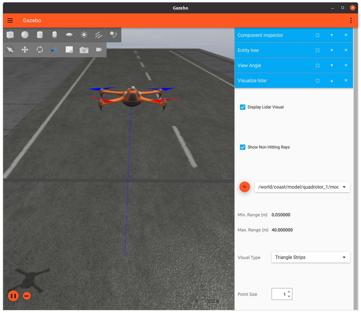
Here is a screenshot of the simulator with point lidar sensor data visualization:
The MBZIRC simulator provides two camera models: mbzirc_hd_camera, and mbzirc_vga_camera, both simulated using the camera sensor type. They can be found in the mbzirc_ign/models/sensors directory. The description of the parameters can be found in the sdformat specification page for a sensor element
The steps for customizing camera parameters are very similar to the steps for customizing lidar parameters. Follow the steps described in the single point lidar model example and change the camera parameters in your model.sdf to the values that match your custom camera sensor. Common use cases include updating the camera Field-Of-View (<horizontal_fov>), resolution ( and
<image><height>), and sensor range (<clip><far>) parameters. Note that configuration of the <distortion> parameters is not supported yet. After all the customizations are complete, build and install the colcon workspace for it to take effect.
The second method of creating a custom sensor device is to implement a new one from the ground up. There are 3 main steps:
- Implement the sensor
- Add a model description of the sensor
- Create an Ignition to ROS bridge for the sensor data
We have created a Naive Radar system as an example to show the process of integrating a new custom sensor into the MBZIRC simulator. Note that this is a naive implementation of a radar model and serves as an example. It does not simulate radio wave propagation and interferences. There is also no spinning mechanism for the radar - the range and bearing output corresponds to a single point in time. No Doppler velocity or signal strength data are generated.
Custom sensor implementations should live in a new package in the mbzirc_custom directory. In this example, our implementation is in the mbzirc_naive_radar package.
Here is the directory structure in mbzirc_naive_radar
-
src: Source files of the custom Naive Radar system -
models/sensors: model description of the Naive Radar sensor -
launch: a launch file for spawning the IGN to ROS bridge process
The first step involves creating a new System (plugin) for the base simulator Ignition Gazebo. The core of Ignition Gazebo is built on the Entity-Component-System (ECS) architecture. To have any custom code running on the simulator, you’ll need to write an Ignition Gazebo System, which gets compiled into a shared library and loaded by the simulator at run time. Within a System, you have access to ground truth data such as the pose of entities poses and other physics data that are necessary to simulate and generate sensor data. Note that Systems can be very powerful, therefore custom sensor implementation will need to be carefully audited before being accepted into the simulator. For more information on creating a System for Ignition Gazebo, see the Ignition Gazebo tutorial.
Let's take a look at the Naive Radar system implementation in NaiveRadar.cc. Here are some of the key functions.
Configure: Parses parameters passed to it by the model description file. The parameters are defined in the model.sdf file which will be shown in Step 2.
PostUpdate: This function does the majority of the work for generating radar data. It does the following:
- Throttles the computation based on input
update_rateparameter. - Computes range, azimuth, and elevation data that are typically produced by a radar sensor. Since we have pose data of all entities in simulation, we are able to compute distances and angles between them and the sensor.
- Filters out range, azimuth, and elevation data that are outside of the limits set by user specified parameters:
min_range,max_range,min_angle,max_angle,min_vertical_angle,max_vertical_angle - Adds Gaussian noise to the data
- Publishes the data to an Ignition topic.
A couple of things to point out:
- Ignition does not have a radar message type. So we are using a
Ignition::msgs::Float_Vmessage type as a workaround, which packs the range, azimuth, and elevation data into a float array - The Ignition topic is auto generated based on the model’s scoped name. This is so that we can have a unique topic name for each sensor.
Finally, we need a CMakeLists.txt with commands to build the sensor system. You will notice that the CMakelists.txt also has commands to install model description files to be shown next in Step 2, and build and install a bridge executable in Step 3.
The process of adding a model description is similar what is done in the Customizing lidars section. Each sensor needs to have a model description that must be placed in the mbzirc_custom/<custom_sensor_package>/models/sensors directory. In this example, we have a mbzirc_naive_radar model with the following files:
-
model.sdf: Model description of the custom radar. This is where we attach the Naive Radar System to the model and specify its parameters:
<plugin
    filename="libNaiveRadar.so"
    name="mbzirc::NaiveRadar">
  <update_rate>1</update_rate>
  <scan>
    <horizontal>
      <min_angle>-3.14159265</min_angle>
      <max_angle>3.14159265</max_angle>
    </horizontal>
    <vertical>
      <min_angle>-0.1745</min_angle>
      <max_angle>0.1745</max_angle>
    </vertical>
    <range>
      <min>6.0</min>
      <max>5000.0</max>
    </range>
    <noise>
      <type>gaussian</type>
      <mean>0</mean>
      <stddev>2</stddev>
    </noise>
  </scan>
</plugin>
-
model.config: Meta information about the model in XML format..
The last step is to add a bridge for the sensor data to be published to ROS topics. Recall that in our custom sensor implementation, we published data to Ignition topics instead of ROS topics. This is by design as we will only be allowing communication through Ignition between the simulator machine and the bridge container in the robot machine. Therefore we will need to republish messages from Ignition to ROS.
One difference with the steps shown in the Customizing lidars section is that our example radar implementation publishes messages of a type that is not supported by ros_ign_bridge, see a list of supported types here. So we will create a custom bridge process to do the conversion.
-
The custom sensor bridge is implemented in naive_radar_bridge.cc. It is a ROS node that gets launched whenever a robot is spawned into the simulation. Its main tasks are the following:
- Periodically checks for ROS subscribers, and if found, subscribe to the Ignition topic.
- Converts the Ignition message to ROS message on callback.
- Publishes the ROS message to ROS topic.
A few of things to point out:
- Recall again that in the custom sensor implementation, we packed data to a float array message because there is no corresponding radar data type available in Ignition. On the ROS side, there is however a radar_msgs package available so we are able to populate a
radar_msgs::msg::RadarScanmessage in ROS. We just need to make sure the newradar_msgspackage dependency is added to the package.xml file . - The Ignition topic is passed in using a ROS parameter. We will specify this parameter in our launch file.
- The ROS topic is hardcoded to
radar/scan. We will remap this topic in our launch file.
-
Finally, the simulator will look for a
launch/bridge.launch.pyfile in all custom sensor packages, and if it exists, the launch file will be included as part of the process for spawning a robot into simulation. In our example, we have a launch/bridge.launch.py file for bringing up the bridge node process.
-
To test this custom sensor model, uncomment the
installcommands in the CMakeLists.txt and rebuild your workspace.IGNITION_VERSION=fortress colcon build --merge-install --packages-select mbzirc_naive_radar
- Note: If you are adding your own custom package, make sure to source your
<colcon_ws>/install/setup.bashafter the package is created so the workspace can pick up the new package.
- Note: If you are adding your own custom package, make sure to source your
-
Launch simulation and test spawning a vehicle with a naive radar, e.g.
# launch coast world
ros2 launch mbzirc_ros competition_local.launch.py ign_args:="-v 4 -r coast.sdf"

# spawn the USV with a naive radar in slot0
ros2 launch mbzirc_ign spawn.launch.py name:=usv world:=coast model:=usv x:=-1462 y:=-16.5 z:=0.3 R:=0 P:=0 Y:=0 slot0:=mbzirc_naive_radar

# verify data are published to the ros2 topic
ros2 topic echo /usv/slot0/radar/scan
The previous section demonstrated how to create a custom sensor implementation from the ground up and gave an example of how you can implement a naive radar sensor model. However, before venturing into implementing a completely new sensor from the ground up, check to see if you are able to adapt an existing sensor model to generate data that is similar to those produced by your custom sensor. Another approach for creating a naive radar model would be to use a spinning lidar. For example:
- Create a new planar (or 3d) lidar model with a
<min_angle>and<max_angle>that matches the beam width of the radar. - Set up the model in the
model.sdfso that the sensor is on a separate link from the main body link and connect them using arevolutejoint along the z axis. - Attach a
JointControllersystem to the model for rotating the sensor. - Attach a
JointStatePublishersystem to publish joint angles of the revolute joint.
Here is what the model.sdf looks like.
With this setup, you will now have a spinning lidar that outputs range data (by the lidar) and azimuth data (by the joint state). For any non-infinite range returns (lidar hits), you should also be able to compute its elevation by looking at the index of the lidar ray and and the angle increment size from the lidar scan message. You will then just need to bridge these data from Ignition to ROS following Step 3 in the Creating custom sensor implementation section section and publish a radar message to a ROS topic. This example does not include a custom bridge process.
-
To test this custom sensor model, uncomment the
installcommands in the CMakeLists.txt and rebuild your workspace.IGNITION_VERSION=fortress colcon build --merge-install --packages-select mbzirc_naive_spinning_radar --cmake-clean-cache
- Note: If you are adding your own custom package, make sure to source your
<colcon_ws>/install/setup.bashafter the package is created so the workspace can pick up the new package.
- Note: If you are adding your own custom package, make sure to source your
-
Launch simulation and test spawning a vehicle with a naive spinning radar, e.g.
# launch coast world
ros2 launch mbzirc_ros competition_local.launch.py ign_args:="-v 4 -r coast.sdf"

# spawn the USV with a naive spinning radar in slot0
ros2 launch mbzirc_ign spawn.launch.py name:=usv world:=coast model:=usv x:=-1462 y:=-16.5 z:=0.3 R:=0 P:=0 Y:=0 slot0:=mbzirc_naive_spinning_radar
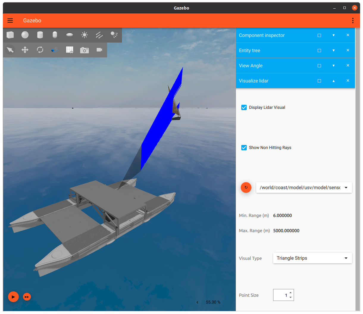
Here is a screenshot of the simulator with naive spinning radar data visualization: