Custom Arm - osrf/mbzirc GitHub Wiki
This page shows how to integrate a custom arm in the MBZIRC simulator. The two main steps are:
The first step is to create a model description of the arm model. For the model to be included in the MBZIRC simulator, a new package needs to be added to the mbzirc_custom directory. Inside the package we need to have a model directory with these 2 files
- model.sdf.erb - An Embedded RuBy (ERB) template file for generating a
model.sdffile of the arm. - model.config: Meta information about the model in XML format.
We use ERB to generate a model.sdf file in a similar way to using xacro for generating URDF files in ROS. The main reason for this is to that we need a way to pass a couple of parameters to the model.sdf file:
-
topic_prefix- A prefix string for the arm joint control topics - we will pass in the name of the USV as the topic prefix. -
gripper- The gripper model to attach to the arm - this is eithermbzirc_suction_gripperormbzirc_oberon7_gripperdepending on what is specified by the user.
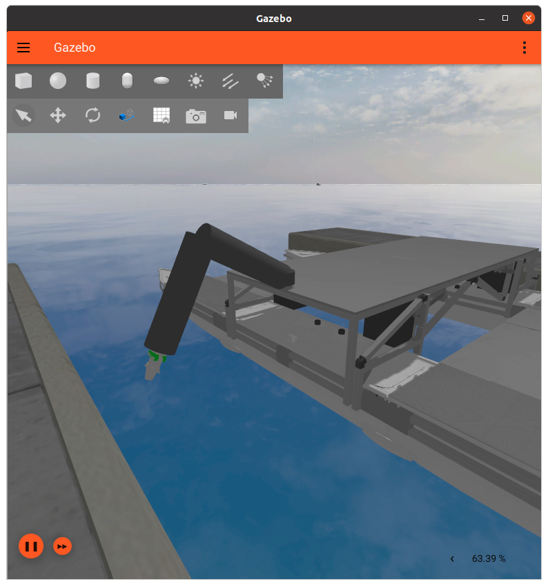
As an example, we added a mbzirc_simple_arm model to illustrate what a basic articulated model looks like. Here is the full model.sdf.erb file. For more information on creating models using SDF, please visit the SDF website.
The simple arm model consists of 3 links:
-
base_link: The canonical base link. This should also be where the origin of the model is, i.e. pose should be at zero, so that when the arm is mounted on the USV, the base link sits nicely on top of the mount point. -
lower_arm_link: Lower section of the arm -
upper_arm_link: Upper section of the arm
Here is an SDF snippet of the lower arm link:
    <link name='lower_arm_link'>
      <pose relative_to='base_link'>0.375 0.0 0.0 0 1.570796 0</pose>
      <inertial>
        <pose>0.0 0.0 0.0 0 0 0</pose>
        <mass>10</mass>
        <inertia>
          <ixx>0.49375000</ixx>
          <ixy>0</ixy>
          <ixz>0</ixz>
          <iyy>0.49375000</iyy>
          <iyz>0</iyz>
          <izz>0.05</izz>
        </inertia>
      </inertial>
      <collision name='lower_link_collision'>
        <geometry>
          <cylinder>
            <length>0.5</length>
            <radius>0.1</radius>
          </cylinder>
        </geometry>
      </collision>
      <visual name='lower_link_visual'>
        <geometry>
          <cylinder>
            <length>0.75</length>
            <radius>0.1</radius>
          </cylinder>
        </geometry>
        <material>
          <diffuse>0.05 0.05 0.05</diffuse>
        </material>
      </visual>
    </link>
We give the link proper mass inertia values. The two arm links use a simple cylinder geometry for both its visual and collisions. Note that the collisions are shorter in length than the visual to avoid self-collision between the links.
One note about geometry shapes, if you have a mesh you like to use for the arm <visual>, such as in the case of mbzirc_oberon7_arm, you will need to break each segment of the arm into multiple meshes and connect them using joints. You can then specify a <mesh> geometry (instead of <cylinder>) with its value pointing to the mesh file. However, for the <collision> element, we ask that you approximate the collisions using simple geometry shapes such as <cylinder> or <box> for better simulation performance.
There are 3 joints in the simple arm model. The first 2 joints, joint_0 and joint_1, connect the links in this simple arm model, while the 3rd joint, joint_2, connects the arm with the nested gripper model specified in the <include> SDF element. Here is what a joint looks like in SDF:
    <joint name='joint_1' type='revolute'>
      <pose relative_to='joint_0'>0.75 0.0 0.0 0 1.570796 0</pose>
      <parent>lower_arm_link</parent>
      <child>upper_arm_link</child>
      <axis>
        <xyz>0 -1 0</xyz>
        <limit>
          <lower>-1.570796</lower>
          <upper>1.5707896</upper>
          <effort>500</effort>
          <velocity>0.15</velocity>
        </limit>
      </axis>
    </joint>
All these joints are all revolute joints (also known as hinge joints). Each provides one degree of freedom between the pair of connected links. Think of it as a servo motor between two links (segments) of the arm. The pair of links attached by this joint are specified via the <parent> and child> SDF elements.
The axis of rotation is specified using the <axis> SDF element, which by default is expressed in the joint frame. We describe its range of motion by specifying the joint limits in radians using the <limit> SDF element. Finally, the <velocity> and <effort> limits should also be set - they affect the speed of arm motion once the controllers are added.
The simple arm model illustrates the most basic arm setup. In a more complex multi-DOF arm configuration, you will essentially add more links and revolute joints to connect them
Please keep the chain of links in a tree structure and avoid forming a graph / loop with the joints (e.g. 4 bar linkage) as it is not properly supported yet.
Now that we have gone through the core model description of the arm with the links, inertial, visual, collision, and joint properties defined, we will show how to add Ignition Systems to the arm for controlling the arm.
Ignition Gazebo provides these two systems that are useful for controlling the arm
-
JointPositionController: Provides position control -
JointTrajectoryControl: Provides trajectory control with feedback
Going back to the model.sdf.erb file in the mbzirc_simple_arm model, we see that 3 JointPositionContoller Systems are attached to the model, one for each joint.
    <plugin
      filename="ignition-gazebo-joint-position-controller-system"
      name="ignition::gazebo::systems::JointPositionController">
      <joint_name>joint_0</joint_name>
      <topic><%= $topic_prefix %>/arm/joint_0</topic>
      <use_velocity_commands>true</use_velocity_commands>
      <initial_position>0.5</initial_position>
    </plugin>
The parameters are:
-
<joint_name>: Name of the arm to control -
<topic_name>: Name of the topic to subscribe to for joint commands -
<use_veloicty_commands>: Controller operation mode. True to bypass the internal PID controller used for position control.- We recommend setting this to true for more accurate and stable position control.
-
<initial_position>: Initial position of the joint. Optional.
The last optional step is to add a JointStatePublisher system to publish joint position (radians) and velocity (radians / second) data so you can get feedback on joint data. This is analogous to reading data from joint encoders.
    <plugin filename="libignition-gazebo-joint-state-publisher-system.so" name="ignition::gazebo::systems::JointStatePublisher">
      <joint_name>joint_0</joint_name>
      <joint_name>joint_1</joint_name>
      <joint_name>joint_2</joint_name>
    </plugin>
Only one JointStatePublisher system is needed for the whole arm model since it is able to accept multiple <joint_name> parameters.
The JointPositionController and JointStatePublisher Systems that we added to the arm subscribe and publish messages to Ignition topics. In order to control the arm and listen to its joint states using ROS, we will need to create a bridge for these topics. Luckily, since these Systems use common message types that are supported by the ros_ign_bridge, we do not need to implement a custom bridge process like in the custom sensor example. All we need to do is supply a bridge launch file in our custom arm package to bring up the bridge process.
In the mbzirc_simple_arm example, we place a bridge.launch.py file in the launch directory. When a robot is spawned into the simulation, the simulator will look for this file in your custom model package, and if it exists, this launch file will be included as part of the spawn process.
Looking at the bridge.launch.py implementation in more detail, you will notice that the launch file brings up a node with multiple bridges.
    # arm joint states
    bridges.append(
        mbzirc_ign.bridges.arm_joint_states(world_name, model_name)
    )

    # arm joint pos cmd
    arm_joints = ['joint_0', 'joint_1', 'joint_2']
    for joint in arm_joints:
        bridges.append(
            mbzirc_ign.bridges.arm_joint_pos(model_name, joint)
        )
There is one bridge for the joint states topic, and one bridge for each joint position command topic. The mbzirc_ign python module provides convenient functions for defining the bridge arguments and topic name remapping between the IGN and ROS topics, see mbzirc_ign/src/mbzirc_ign/bridges.py. If you have sensors mounted on the arm, you can also use one of these helper functions.
-
To test this custom sensor model, uncomment the
installcommands in the CMakeLists.txt and rebuild your workspace.IGNITION_VERSION=fortress colcon build --merge-install --packages-select mbzirc_simple_arm --cmake-clean-cache
- Note: If you are adding your own custom package, make sure to source your
<colcon_ws>/install/setup.bashafter the package is created so the workspace can pick up the new package.
- Note: If you are adding your own custom package, make sure to source your
-
Launch simulation and test spawning the USV with the simple arm model, e.g.
# launch coast world
ros2 launch mbzirc_ros competition_local.launch.py ign_args:="-v 4 -r coast.sdf"

# spawn the USV with the simple arm model
ros2 launch mbzirc_ign spawn.launch.py name:=usv world:=coast model:=usv x:=-1462 y:=-16.5 z:=0.3 R:=0 P:=0 Y:=0 arm:=mbzirc_simple_arm gripper:=mbzirc_oberon7_gripper

# verify joint states are published to the ros2 topic
ros2 topic echo /usv/arm/joint_states

# try controlling the arm
ros2 topic pub --once /usv/arm/joint/joint_0/cmd_pos std_msgs/msg/Float64 'data: 1.0'
ros2 topic pub --once /usv/arm/joint/joint_1/cmd_pos std_msgs/msg/Float64 'data: 1.0'
ros2 topic pub --once /usv/arm/joint/joint_2/cmd_pos std_msgs/msg/Float64 'data: 1.0'