Interfaces Method for Super Network Drawings - nasa/gunns GitHub Wiki
This page describes the Interfaces Method for creating and maintaining super-network drawings. Refer here for a refresher and background on super-networks, the drawings, and the other Super-Ports Method for using them.
Workflow
This is the process for using the Interfaces Method. We'll detail these more below:
- Add Sub-Network Interface objects (from the GUNNS_Super.xml shape library) to your sub-network drawings and configure them.
- Define the Key attribute for every node shape in the Sub-Network Interfaces.
- Save and netexport.py the sub-network drawings. This is a crucial step because the netexport.py script generates and stores information about the interfaces in the drawing, for use by the supcreate.py and supexport.py scripts.
- Create the super-network drawing using the supcreate.py script, like normal.
- In the super-network drawing, connect compatible Sub-Network Interfaces between sub-networks with the Sub-Network Interface Connection lines (from the GUNNS_Super.xml shape library).
- Run the supexport.py script, like normal.
Configure interfaces in your sub-networks
Whereas the Super-Ports Method allows you to use a sub-network drawing as-is without any pre-conditions, this Interfaces Method requires you to first add Sub-Network Interfaces to the sub-network drawings that you want to connect.
A Sub-Network Interface is just a container of node shapes in your sub-network. It defines a set of nodes that are paired with their counterparts in a Sub-Network Interface in another sub-network. The nodes are paired by defining a 'Key' attribute that matches between each set of nodes.
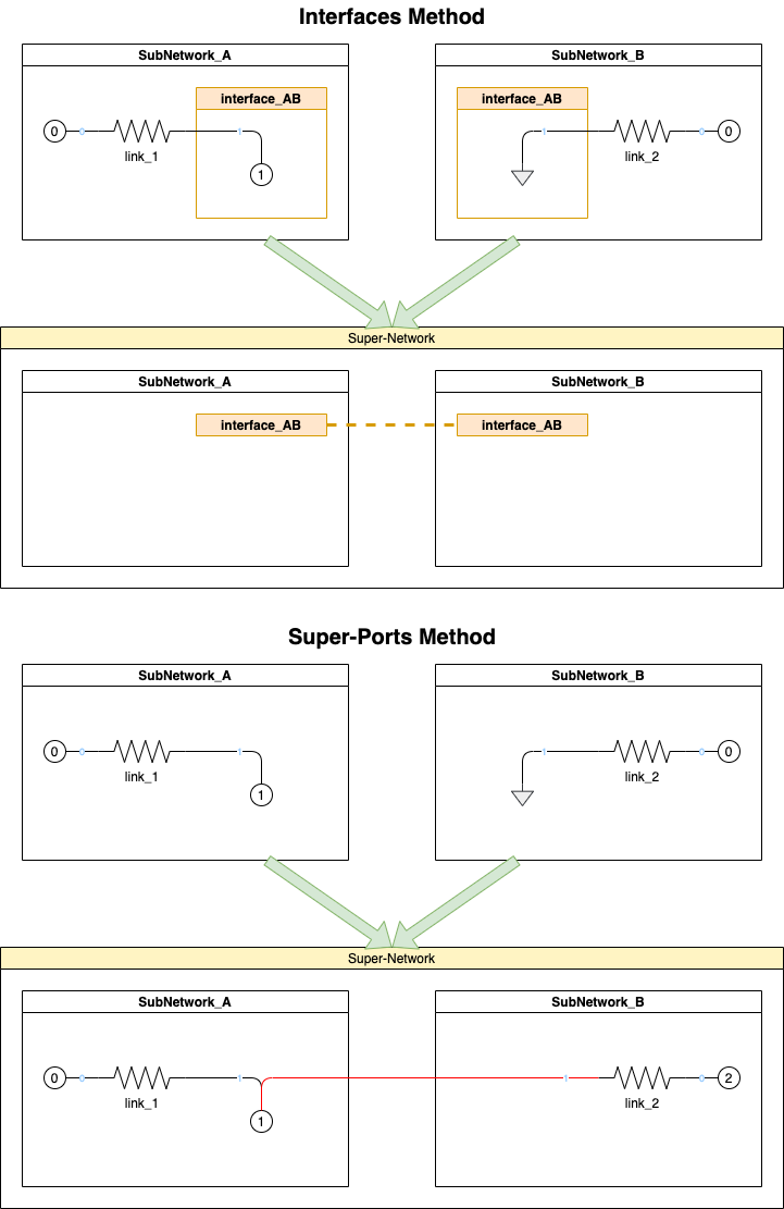
To illustrate, the connections made between these two sub-networks, using the Interfaces Method and Super-Port Method, are equivalent. In both methods, Port 1 of link_2 in SubNetwork_B is overridden to connect to Node 1 in SubNetwork_A:
Some details about setting up these Sub-Network Interfaces:
- You can have any number of Sub-Network Interfaces in a sub-network.
- Each Sub-Network Interface must have a unique name in its sub-network, unless they are duplicated Interfaces (below). These names are what you see in the super-network drawing, so we recommend using descriptive names for the things they interface. These names are not C/C++ variables, so they can have spaces in them, etc.
- Duplicated Sub-Network Interfaces are allowed. A duplicate Interface is when two or more Interfaces have the exact same name, nodes and node keys. This might be useful in a large, complicated sub-network drawing that has links on opposite sides of the drawing that need to connect to the same Interface, and it is clearer or more convenient to have copies of the same Interface near each side for them to connect to.
- A Sub-Network Interface can contain normal numbered nodes, reference nodes, or ground nodes.
- A Sub-Network Interface can contain 1 or more nodes.
- The Sub-Network Interface shape is found in the gunns/draw/libraries/GUNNS_Super.xml shape library. Drag it into your network, change its name, and move nodes into it.
- It's your preference as to whether to open or collapse the Sub-Network Interface container. We recommend leaving them open in your sub-network drawing, so you can see which links connect to which nodes in it, and leave it collapsed in the super-network drawing.
- Every node shape within the Sub-Network Interfaces requires a shape data attribute called Key.
- The node shapes do not have this by default, so you must either add them manually (recommended), or let the netexport.py script add them.
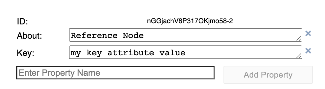
- To add the Key attribute manually, right-click on the node shape and select Edit Data. In the pop-up data editing window, enter Key in the "Enter Property Name" field and click the Add Property button, then enter your desired value for the Key property.
- The Key value can be any string you like -- it doesn't become a C/C++ variable so it can have spaces, etc.
- The netexport.py script will add a Key attribute to any such nodes that are missing it.
- It will give the Key a default value.
- You will need to reopen the drawing and change the default Key values assigned by netexport.py so that they will match the Keys in the connected Sub-Network Interfaces in other networks.
- Because this is more effort, it's better to add the Keys manually when you first create the Sub-Network Interfaces.
- The Key data should look something like below in the data edit window:
Sub-Network Interface Connections and Compatibility
In the super-network drawing, you connect Sub-Network Interfaces together with the Sub-Network Interface Connection lines. However, if the connected interfaces are not compatible, the supexport.py script will abort with an error. For connected interfaces to be compatible:
- Each interface must have the same number of node shapes.
- All nodes must have Key attributes.
- The set of Key attributes must match, i.e. the set of Keys in one interface must match the set of Keys in the other interface.
- For each Key value in the connected interfaces, there should be exactly 1 numbered node, and the rest must be Ground nodes.
- You can connect more than 2 interfaces together, provided the above rules are met.
- Whereas the node Keys must match between all connected interfaces, the interface container names do not have to match.
- Note that you cannot use both Super-Port connections and Sub-Network Interface connections in the same super-network drawing. This would be trying to use both the Super-Ports Method and Interface Method, which would defeat the purpose of using the Interface Method. The supexport.py script will error out if you try to use both in the same super-network drawing.
- Duplicate Sub-Network Interfaces in a sub-network drawing (above) are not copied into the super-network drawing -- only the original, or first of them is. The link connections to the duplicate Interfaces are stored in the original instance, so no information is lost. This simplifies the super-network drawing by eliminating duplicate copies of the same interface.
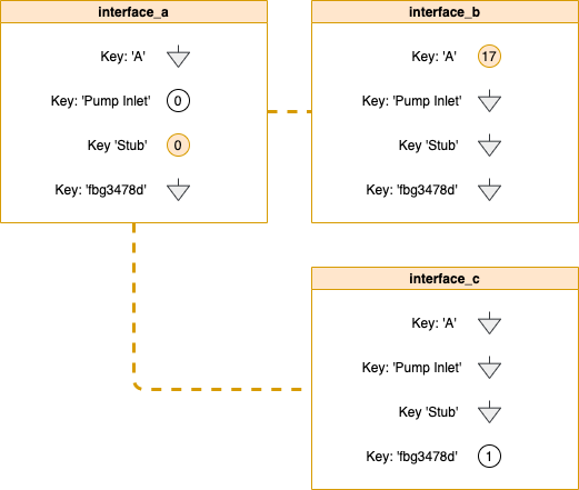
This illustrates an example of 3 interfaces connected together. We show the example Key values, but they would actually be attributes of the node shapes, as described above:
How connections work, and general comments
Every link port that connects to a Ground node in a Sub-Network Interface is overridden, in the super-network configuration Python file exported by supexport.py, to connect to the numbered node with the same Key value in the connected interface. Refer to the first drawing above. Since port 1 of link_2 in SubNetwork_B connects to an interface Ground node, it ends up connected to the numbered node (1) in the connected interface in SubNetwork_A. The shared Key value of the interface nodes determines which interfaces nodes, and therefore the link ports connected to them, become connected. A link port that connects to a numbered node in an interface is not actually moved - instead, the links that connect to the Ground interface nodes with the same key are moved to its numbered node.
Note that when we export the super-drawing with supexport.py, it doesn't re-number the numbered nodes within the Sub-Network Interfaces. Contrast this to the Super-Ports Method, which does renumber all nodes to reflect their actual node number in the super-network. We leave the nodes within the Sub-Network Interfaces alone, so that you can more easily refer back to them in their source sub-network drawings.
The Interfaces Method results in a super-drawing that is higher-level and less detailed than a Super-Ports drawing. The only details you'll see in the Interfaces Method super-drawing are the names of the sub-networks and their interfaces. Therefore it is important that you give them useful, descriptive names that help the user tell what is connected to what, at this level.
When looking an an Interfaces Method super-drawing, you will need to refer back to the sub-network source drawings to get details on what's really connected. In the super-drawing, each sub-network box contains a data attribute giving the location and filename of their source drawing. Refer to this as a reminder of where to look for their source drawing.
The Keys are Key
The node Key attributes are really what tie it all together. But the Key values aren't displayed in the drawing, and you have to hover over a node to see the Key value in the shape data pop-up. Because this is a bit time-consuming way to check which nodes are connected, we suggest you also arrange the nodes in matching order within their Interface boxes. The scripts don't care how they are arranged within the interfaces boxes - they use the Key instead. But arranging them consistently will help you more easily cross-reference the paired nodes together.
Modify & Export a Super-Network: supexport.py
You run supexport.py just the same way as you do with the Super-Ports Method (see here for a review).
The -u PROJECT_PATH option works with the Interfaces Method, however you must remember to always netexport.py your sub-network drawing changes before you run supexport.py to update the super-network drawing.
Adding & Deleting Sub-Networks
Sub-networks and their Sub-Network Interfaces can be added or deleted from the super-network drawing after it has been created. Deleting is easy, just delete the Interface or whole sub-network as desired.
However, adding a new Sub-Network is a bit trickier. Export your source sub-network drawing using netexport.py first. Then copy & paste it into your super-network drawing, same as you would in the Super-Ports Method. Then (this is the extra step) you should manually delete everything out of that sub-network except for the Sub-Network Interfaces and their contained nodes. I think if you leave those extra objects in the sub-network, the supexport.py script will still work, but leaving that clutter in defeats the purpose of using the Interfaces Method, which is to keep the content of the super-network drawing as small as possible for speed and clarity.