GunnsGasTurbine - nasa/gunns GitHub Wiki

This extends GunnsFluidConductor with a model of a gas turbine, such as used in gas turbine engines. Its purpose is to model pressure drop, flow rate, and power generation.
This model relies on user-supplied turbine performance maps to model turbine efficiency, and the relationship between flow rate and pressure drop. The efficiency map is a 5th order polynomial, while the relationship between pressure and flow rate is a modified power function. The user must supply two of each of these functions, at two operating shaft speeds. These operating speeds should ideally enclose the expected operating conditions of the turbine. Performance at speeds between these references are calculated by the model using interpolation.
This model can be used by the GunnsDriveShaftSpotter model to simulate a drive shaft connection between a compressor/fan and turbine.
This link is designed to interface with a motor or drive shaft model. The motor/shaft model supplies a shaft rotational speed to the turbine, and the turbine returns a shaft torque to the motor/shaft model. The shaft torque is due to the useful work done on the shaft by the fluid.
This link models isentropic expansion across the turbine and convection heat transfer between the fluid and the turbine wall, similar to fan links. This link does not modify the mixture of the fluid passing through it.
This link has the same connection rules as GunnsFluidConductor. Multiple turbines can be staged in any combination, either in parallel or series, and in sympathetic or opposing directions and interact in a realistic manner.
Port Connection Rules (These are limitations on the port connection to nodes that the link enforces in run-time):
- Same as GunnsFluidConductor.
Other Rules (These are extra rules you should always try to follow):
- Do not mix fluid phases across the link. Both nodes should only contain gas phase.
- As with normal conductors, try to combine conductors and GunnsGasTurbines in series into a single GunnsGasTurbine whenever possible to reduce network node count.
- The network solver has a configuration parameter called minLinearizationP which can interfere with the performance of this link if has too high a value. Always set this parameter to less than 5% of the lowest pressure drop that any of the turbines in your network are expected to operate at. In other words, with all turbines spinning at their lowest operating speeds, and with all plumbing that they flow through as wide-open as possible, the lowest pressure drop across any of the turbines.
- As with fans, it is a good idea to add some volume to the turbine's downstream node. This promotes model stability.
- Always finish tuning this link and the system that it flows through before you attempt to hook up and tune a motor or drive shaft model, integrate with compressor stages, etc.
Configuration Data Parameters:
TODO explain corrected mass flow rate & correctd spin speed used by the example curves. Chris sending me example curves for efficiency & p drop. Low & high reference spin speeds bound the operating speed range of the turbine, and are the speeds at wich the reference efficiency & flow rate curves are defined.
- maxConductivity: Same as GunnsFluidConductor.
- expansionScaleFactor: Same as GunnsFluidConductor. This scales the isentropic temperature drop across the turbine. Although the turbine models varying isentropic efficiency based on operating condition, the temperature drop always uses this one fixed scale factor. So it's best to tune this to match the most typical operating point of your turbine.
- referenceTemp (default = 0 (K), must be > 0): This is the temperature for the reference performance curves.
- referencePress (default = 0 (kPa), must be > 0): This is the pressure for the reference performance curves.
The following terms define the turbine flow rate vs. pressure ratio performance curves. There are two defined curves: one for the lowest operating spin speed, and one for the highest spin speed. These curves are a modified power function of corrected flow rate as a function of pressure ratio:
- We define inlet to exit pressure ratio PR as
- Corrected mass flow rate ṁcorrect is, where ṁmax, C1 and C2 are configuration data terms described below:
- The above will approach zero as PR ➝ 1 and approach ṁmax as PR ➝ ∞.
- Actual mass flow rate ṁ is related to corrected mass flow rate as:
- Below is an example of what your curve fits should look like. Note this shows separate curves at many speeds, but you're only defining the lowest and highest speed bounding curves. Also this labels the speed curves with speed ratios relative to a design point speed (0.6, 1.0, 1.2, etc) but your speeds are in actual (rev/min) units, defined later:
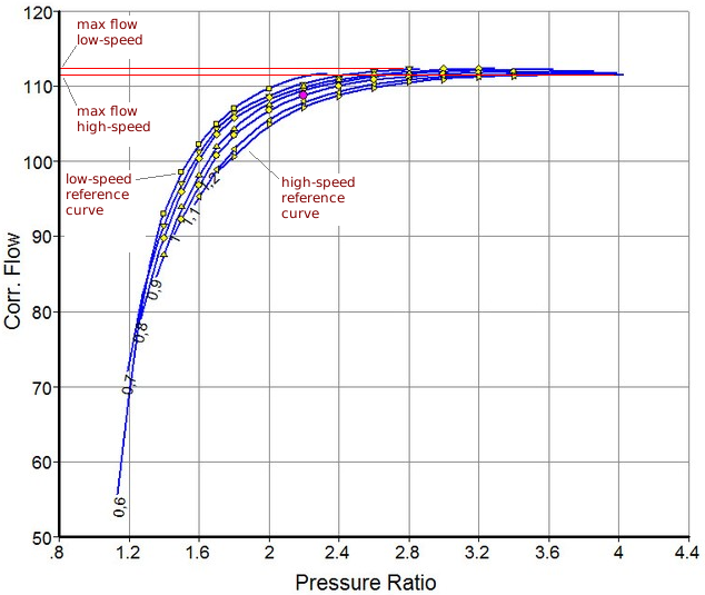
- maxFlowLowSpeed (default = 0 (kg/s), must be > 0): This is the maximum corrected mass flow rate ṁmax through the turbine for the low reference corrected spin speed.
- maxFlowHighSpeed (default = 0 (kg/s), must be > 0): This is ṁmax for the high reference corrected spin speed.
- coeffLowSpeed1 (default = 0): This is the coefficient C1 for the low reference corrected spin speed, in the above equation for corrected mass flow.
- coeffHighSpeed1 (default = 0): This is C1 for the high reference corrected spin speed.
- coeffLowSpeed2 (default = 0): This is the coefficient C2 for the low reference corrected spin speed, in the above equation for corrected mass flow.
- coeffHighSpeed2 (default = 0): This is C2 for the high reference corrected spin speed.
The following terms define the turbine efficiency vs. pressure ratio performance curves. There are two defined curves: one for the lowest operating spin speed, and one for the highest spin speed. These curves are up to a 5th-order polynomial defining efficiency as a function of pressure ratio:
- The corrected spin speed Ncorrect is related to actual spin speed N by the reference and actual inlet temperatures as:
- Below is an example of what your curve fits should look like:
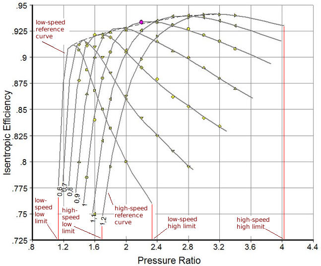
- efficiencyCoeffLow0 (default = 0): This is the 0th-order polynomial coefficient for the low corrected speed reference efficiency curve.
- efficiencyCoeffLow1 (default = 0): This is the 1th-order polynomial coefficient for the low corrected speed reference efficiency curve.
- efficiencyCoeffLow2 (default = 0): This is the 2th-order polynomial coefficient for the low corrected speed reference efficiency curve.
- efficiencyCoeffLow3 (default = 0): This is the 3th-order polynomial coefficient for the low corrected speed reference efficiency curve.
- efficiencyCoeffLow4 (default = 0): This is the 4th-order polynomial coefficient for the low corrected speed reference efficiency curve.
- efficiencyCoeffLow5 (default = 0): This is the 5th-order polynomial coefficient for the low corrected speed reference efficiency curve.
- efficiencyCoeffHigh0 (default = 0): This is the 0th-order polynomial coefficient for the high corrected speed reference efficiency curve.
- efficiencyCoeffHigh1 (default = 0): This is the 1th-order polynomial coefficient for the high corrected speed reference efficiency curve.
- efficiencyCoeffHigh2 (default = 0): This is the 2th-order polynomial coefficient for the high corrected speed reference efficiency curve.
- efficiencyCoeffHigh3 (default = 0): This is the 3th-order polynomial coefficient for the high corrected speed reference efficiency curve.
- efficiencyCoeffHigh4 (default = 0): This is the 4th-order polynomial coefficient for the high corrected speed reference efficiency curve.
- efficiencyCoeffHigh5 (default = 0): This is the 5th-order polynomial coefficient for the high corrected speed reference efficiency curve.
- minEffLimitLowSpeed (default = 0, must be > 0): This is the lower bound on evaluations of the low corrected speed efficiency curve.
- minEffLimitHighSpeed (default = 0, must be > 0): This is the lower bound on evaluations of the high corrected speed efficiency curve.
- maxEffLimitLowSpeed (default = 0, must be > minEffLimitLowSpeed): This is the upper bound on evaluations of the low corrected speed efficiency curve.
- maxEffLimitHighSpeed (default = 0, must be > minEffLimitHighSpeed): This is the uppper bound on evaluations of the high corrected speed efficiency curve.
- correctedSpeedLow (default = 0 (rev/min), must be > 0): This is the corrected spin speed at which the low-speed reference curves are defined.
- correctedSpeedHigh (default = 0 (rev/min), must be > 0 and != correctedSpeedLow): This is the corrected spin speed at which the high-speed reference curves are defined.
- filterGain: same as GunnsGasFan.
- driveRatio: same as GunnsGasFan.
- thermalLength: same as GunnsFluidValve.
- thermalDiameter: same as GunnsFluidValve.
- surfaceRoughness: same as GunnsFluidValve.
Input Data Parameters:
- malfBlockageFlag: Same as GunnsFluidConductor.
- malfBlockageValue: Same as GunnsFluidConductor.
- motorSpeed: Same as GunnsGasFan.
- wallTemperature: Same as GunnsFluidValve.
- N/A
- N/A